EP1077519B1 - Verfahren zum Betreiben einer Überspannungsschutzeinrichtung sowie Überspannungsschutzeinrichtung mit mindestens einem Grobschutz- und einem Feinschutzelement - Google Patents
Verfahren zum Betreiben einer Überspannungsschutzeinrichtung sowie Überspannungsschutzeinrichtung mit mindestens einem Grobschutz- und einem Feinschutzelement Download PDFInfo
- Publication number
- EP1077519B1 EP1077519B1 EP20000111588 EP00111588A EP1077519B1 EP 1077519 B1 EP1077519 B1 EP 1077519B1 EP 20000111588 EP20000111588 EP 20000111588 EP 00111588 A EP00111588 A EP 00111588A EP 1077519 B1 EP1077519 B1 EP 1077519B1
- Authority
- EP
- European Patent Office
- Prior art keywords
- spark gap
- impedance
- partial
- sensitivity
- protection element
- Prior art date
- Legal status (The legal status is an assumption and is not a legal conclusion. Google has not performed a legal analysis and makes no representation as to the accuracy of the status listed.)
- Expired - Lifetime
Links
- 238000000034 method Methods 0.000 title claims description 8
- 230000004044 response Effects 0.000 claims description 17
- 239000002800 charge carrier Substances 0.000 claims description 6
- 238000013459 approach Methods 0.000 claims description 4
- 150000002500 ions Chemical class 0.000 claims description 3
- 230000000694 effects Effects 0.000 description 5
- 230000001681 protective effect Effects 0.000 description 5
- 230000004913 activation Effects 0.000 description 3
- 238000009795 derivation Methods 0.000 description 3
- 230000015572 biosynthetic process Effects 0.000 description 2
- 239000007789 gas Substances 0.000 description 2
- 230000005923 long-lasting effect Effects 0.000 description 2
- 230000001012 protector Effects 0.000 description 2
- 241001295925 Gegenes Species 0.000 description 1
- 230000009471 action Effects 0.000 description 1
- 230000008859 change Effects 0.000 description 1
- 230000001419 dependent effect Effects 0.000 description 1
- 230000001627 detrimental effect Effects 0.000 description 1
- 238000011161 development Methods 0.000 description 1
- 230000018109 developmental process Effects 0.000 description 1
- 238000010586 diagram Methods 0.000 description 1
- 238000007599 discharging Methods 0.000 description 1
- 230000003628 erosive effect Effects 0.000 description 1
- 238000000605 extraction Methods 0.000 description 1
- 230000002349 favourable effect Effects 0.000 description 1
- 238000009434 installation Methods 0.000 description 1
- 229910044991 metal oxide Inorganic materials 0.000 description 1
- 150000004706 metal oxides Chemical class 0.000 description 1
- 230000008569 process Effects 0.000 description 1
- 239000004065 semiconductor Substances 0.000 description 1
- 238000000926 separation method Methods 0.000 description 1
- 239000007787 solid Substances 0.000 description 1
Images

Classifications
-
- H—ELECTRICITY
- H02—GENERATION; CONVERSION OR DISTRIBUTION OF ELECTRIC POWER
- H02H—EMERGENCY PROTECTIVE CIRCUIT ARRANGEMENTS
- H02H9/00—Emergency protective circuit arrangements for limiting excess current or voltage without disconnection
- H02H9/04—Emergency protective circuit arrangements for limiting excess current or voltage without disconnection responsive to excess voltage
- H02H9/06—Emergency protective circuit arrangements for limiting excess current or voltage without disconnection responsive to excess voltage using spark-gap arresters
-
- H—ELECTRICITY
- H02—GENERATION; CONVERSION OR DISTRIBUTION OF ELECTRIC POWER
- H02H—EMERGENCY PROTECTIVE CIRCUIT ARRANGEMENTS
- H02H9/00—Emergency protective circuit arrangements for limiting excess current or voltage without disconnection
- H02H9/04—Emergency protective circuit arrangements for limiting excess current or voltage without disconnection responsive to excess voltage
- H02H9/042—Emergency protective circuit arrangements for limiting excess current or voltage without disconnection responsive to excess voltage comprising means to limit the absorbed power or indicate damaged over-voltage protection device
Definitions
- the invention relates to a method for operating an overvoltage protection device, which at least one coarse protection element and a fine protection element and wherein the overvoltage protection device between energy source and consumer is switched, as well as an overvoltage protection device according to the preamble of claim 1 or 4.
- a first stage takes over the so-called coarse protection, i.e. the derivative of the large surge current.
- a subordinate one second stage, namely the fine protection may be due to the lower discharge capacity derive only the residual disturbances, the latter, however, provides the desired low level of protection for sure. Accordingly, there is a separation of functions between the Stage for the derivation of the surge current and the further stage, the ensures the actual level of protection.
- arresters of the coarse protection level are usually spark gaps provided according to the use cases are designed. In particular, find lightning current carrying or Lightning current carrying and subsequent current extinguishing spark gaps Commitment.
- Such conventional spark gaps have in the But usually a very high voltage protection level in the kilovolt range, the in relation to the dielectric strength of the protective equipment and equipment is too high. That's why one will further, i. formed the mentioned fine protection level, the e.g. a varistor.
- This fine protection level ensures the desired level of protection for the equipment and installations.
- One Decoupling element between the stages ensures that each the arrester elements only so strong at the discharge of the surge current involved, as required by the respective design.
- overvoltage protection devices only in the moment of overvoltage limitation and derivation are active and in the remaining time none Show effects on the equipment and systems to be protected. Even during the actual derivation of the overvoltage should the reaction of the protective devices to the system to be protected be as low as possible.
- Components with continuous current / voltage characteristics such as metal oxide varistors or suppressor diodes are a preferred one Means for fine protection, because due to the impedance after Response and during the discharge process it does not occur a short circuit-like state can come. Farther Such components have an ideal protection characteristic for almost every voltage value. However, a major disadvantage of such components is in the relatively low surge current carrying capacity, which due to the conduction in the semiconductor solid state can not be significantly improved.
- a disadvantage of such spark gaps is the occurrence a short-circuit-like state after the response due the given discontinuous U / I characteristic.
- This Senses is a spark gap, so to speak, with a mechanical one Switch comparable.
- the existing low impedance causes an undesirable short circuit condition, wherein furthermore It is disadvantageous that the protective characteristic itself is not constant, but is a function of the steepness of the overvoltage. Of the Value of the limiting voltage at spark gaps can be also only with great effort influence.
- This optionally rated sub-stream becomes a special one Spark gap supplied to cause there a preionization.
- the type of power extraction and the amount of ions formed can be the response and the Time of ignition of the coarse protection spark gap depending on of the load capacity of the fine protection element then in be controlled in a surprisingly simple way.
- the coarse-protection spark gap ensures that the first activated Fine protection element within its load capacity Voltage peaks and currents dissipates without the main spark gap ignited, but on the other hand it is guaranteed that the fine protection element in the context of its operational parameters nondestructive can be operated.
- the spark gap of the coarse protection element has a partial spark gap low response voltage, which is the partial flow is fed from the fine protection stage.
- the first partial spark gap forms together with the current decoupling from the branch of the fine protection element quasi a measuring device for the energetic load.
- the as branched off Measuring current to be considered current then ionized over an auxiliary arc, located in the first part spark gap trains, the arc space of the second or main spark gap.
- the Discharge is determined by adjustable impedance ratios and / or the specific dimensioning of the spark gap, the arrangement preferably as a three-electrode spark gap is trained.
- the partial stream which is derived from the fine protection branch can be set via linear or nonlinear impedances and be given, with time as a further predictor over the Stromflußdauer is given, which the exposure of the current fault corresponds.
- the required ionization charge quantities Qz for igniting the Coarse-protection spark gap are determined by their geometry parameters established.
- the adjustable is, with fixed Zündladungsmenge Qz the time window the activation of the main spark gap pretend arbitrary.
- the overvoltage protection device containing coarse protection and fine protection elements consists of a coarse protection element in the form of an encapsulated three-electrode spark gap, for example, wherein the electrodes form two spark gaps with different ignition voltages.
- the first of the two spark gaps is acted upon by a current flowing through the fine protection element or a partial current diverted therefrom.
- the first spark gap has a relatively low ignition voltage, which releases this first spark gap ions as measure and image for the energetic load of the fine protection element with the onset of early ignition and these are the second spark gaps supplied.
- This second spark gap has a much higher response or ignition voltage, which can be done depending on the ratio of the forming partial arcs of the spark gaps a time-shifted and controlled ignition of these.
- a first impedance Z 1 is provided between the fine protection element with a given impedance Z 3 and the electrode of the first spark gap, wherein a second impedance Z 2 is connected to ground at the node between the first impedance Z 1 and the fine protection element.
- the second impedance may be formed as a transformer to whose primary circuit the first impedance Z 1 is connected and whose secondary circuit determines the value of the second impedance Z 2 .
- the three-electrode spark gap is designed so that the Distances of the electrodes and / or their diameter of Arc chambers for the formation of different partial arcs the partial spark gaps are in a predetermined ratio, which is essentially 1:10.
- the first impedance Z 1 should be substantially approximately ten times the impedance Z 3 of the fine protection element.
- control takes place solely via the design of the partial spark gaps, in which case the second partial spark gap should have a response voltage substantially greater than the response voltage of the first part spark gap is.
- the coarse protection element should have at least two partial spark gaps with a first auxiliary spark gap, which produces after its ignition by means of the ionized gases of Vorlichtbogens charge carriers, which are introduced into the main spark gap, so that the latter is pre-ionized.
- the main spark gap which can be ignited via the preionization of the auxiliary spark gap must be capable of conducting and discharging the entire surge current.
- Such behavior can be achieved by different electrode distances, so that a favorable ratio of the partial arcs with optimal control effect for the time-delayed ignition of the partial spark gaps is given.
- a similar behavior can be achieved by a variation of the chamber diameter.
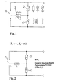
- the basic circuit variant shown in FIG. 1 goes from a stepped surge protection device with coarse protection element 1 in the manner of a three-electrode spark gap and a fine protection element 2 connected in parallel.
- the Fine protection element 2 a varistor, an ohmic resistance, be a suppressor diode or a similar known element, as this is symbolically represented.
- the three-electrode spark gap 1 can be supplied with a pre-ionization current as a coarse protective element.
- the impedance Z 1 is connected to a node of a series circuit of fine protection element 2 with a second impedance Z 2 (reference 4).
- the overvoltage protection device is used in a known manner in a low-voltage system, both stages are designed as parallel-connected line branches between leads, which connect an energy source and a consumer with each other.
- the impedance Z 2 can be designed as an ohmic resistance, but also as a transformer or transformer or pure inductance.
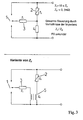
- the embodiment shown in the lower part of FIG. 3 represents a variation of the second impedance Z 2 , which comprises a transformer 5.
- the first impedance Z 1 is connected, wherein the secondary circuit of the transformer 5 determines the value of the second impedance Z 2 .
- two partial spark gaps FS1 and FS2 are formed, wherein the spacing of the electrodes for the partial spark gap FS1, namely 11, is substantially smaller than the distance 12 between the electrodes of the partial spark gap FS2.
- the first impedance Z 1 leads to the second electrode of the first partial spark gap FS1.
- first a current flows through the fine protection element 2 with a resulting partial current via the impedance Z 1 to the electrode of the partial spark gap FS1. Due to a correspondingly low response or ignition voltage, this first partial spark gap FS1 now ignites and releases charge carriers which are supplied to the second partial spark gap FS2 for their pre-ionization.
- the ratio of the electrode spacings 11 and 12 is preferred about 1:10, so that a corresponding ratio of Partial arcs with optimized control effect and the desired time-delayed ignition of the partial spark gaps results.
- the ionized gases generated in the partial spark gap FS1 respectively the resulting pre-arc produces charge carriers, which is a measure of the energetic load of the fine protection element 2 represent.
- the main spark gap which takes place via the preionization, takes over the Three-electrode spark gap the entire surge current, so that in the Case corresponding to large disturbances the fine protection element. 2 is protected.
- the required ionization charge quantities Qz to ignite the spark gaps are determined by the geometry parameters set, so that appropriate opportunities for energetic coordination of the effects or the response of fine protection element and coarse protection element result.
- the charge carrier flow from the partial spark gap FS1 into the space of the partial spark gap FS2 takes place until the spark gap ignites. After this complete ignition of FS2 this completely takes over the interference current and relieved in the desired manner the fine protection element, so that it is protected.
- the degree of discharge is, as described, determined by the impedance ratios in the pitch circles and can be controlled by their dimensioning.
Landscapes
- Emergency Protection Circuit Devices (AREA)
Description
Die erste der zwei Funkenstrecken ist mit einem durch das Feinschutzelement fließenden Strom oder einem hieraus abgezweigten Teilstrom beaufschlagt. Die erste Funkenstrecke weist eine relativ niedrige Zündspannung auf, wodurch mit einsetzender frühzeitiger Zündung diese erste Funkenstrecke Ionen als Maß und Abbild für die energetische Belastung des Feinschutzelements freisetzt und diese der zweiten Funkenstrecken zugeführt werden. Diese zweite Funkenstrecke besitzt eine wesentlich höhere Ansprech- oder Zündspannung, wodurch in Abhängigkeit vom Verhältnis der sich ausbildenden Teillichtbögen der Funkenstrecken ein zeitversetztes und gesteuertes Zünden dieser erfolgen kann.
Die über die Vorionisation der Hilfsfunkenstrecke zündbare Hauptfunkenstrecke muß in der Lage sein, den gesamten Stoßstrom zu führen und abzuleiten.
Ein solches Verhalten läßt sich durch unterschiedliche Elektrodenabstände erreichen, so daß ein günstiges Verhältnis der Teillichtbögen mit optimaler Steuerwirkung für das zeitversetzte Zünden der Teilfunkenstrecken gegeben ist.
Speziell bei Funkenstreckenanordnungen mit ausgebildeten Lichtbogenkammern läßt sich ein ähnliches Verhalten durch eine Variation des Kammerdurchmessers erreichen.
- Fig. 1
- eine prinzipielle Schaltungsvariante einer Überspannungsschutzeinrichtung mit Dreielektroden-Funkenstrecke;
- Fig. 2
- ein Prinzipschaltbild mit einer Steuerung allein über die Ausbildung der Funkenstrecke und einer Impedanz Z2 gegen ∞ bei Z1 im Milliohm-Bereich;
- Fig. 3
- eine Steuerung der Teillichtbögen über die Einstellung der Impedanzverhältnisse sowie einer Variante der Impedanz Z2 unter Anwendung eines Transformators oder Übertragers;
- Fig. 4
- ein Grobschutzelement in Form einer Dreielektroden-Funkenstrecke und
- Fig. 5
- ein Grobschutzelement in Form von Lichtbogenkammern mit unterschiedlichem Kammerdurchmesser D1 und D2.
Claims (7)
- Verfahren zum Betreiben einer Überspannungsschutzeinrichtung, welche mindestens ein Grobschutzelement und ein Feinschutzelement enthält und wobei die Überspannungsschutzeinrichtung zwischen Energiequelle und Verbraucher geschaltet ist, wobei zur mittelbaren Bestimmung der energetischen Belastung des Feinschutzelements oder der Feinschutzstufe ein Teilstrom aus der Feinschutzstufe ausgekoppelt wird, welcher eine Vorionisation des als Funkenstrecke ausgebildeten Grobschutzelements bewirkt, weiterhin über die Größe der Stromauskopplung das Ansprechen und der Zeitpunkt der Zündung der Funkenstrecke in Abhängigkeit von der Belastbarkeit des Feinschutzelements steuerbar ist und durch Vorgabe geringer Werte des ausgekoppelten Teilstroms und gegebener Ionisationsladungsmenge Qz der Funkenstrecke des Grobschutzelements ein unerwünschtes Zünden desselben bei kurzen Störimpulsen auch großer Steilheit und Anstiegsgeschwindigkeit unterbunden wird.
- Verfahren nach Anspruch 1,
dadurch gekennzeichnet, daß
die Funkenstrecke des Grobschutzelements eine Teilfunkenstrecke niedriger Ansprechspannung aufweist, zu welcher der Teilstrom fließt, wobei die gezündete Teilfunkenstrecke Ladungsträger freisetzt, welcher einer Hauptfunkenstrecke des Grobschutzelements zur Vorionisation zugeführt wird. - Überspannungsschutzeinrichtung, welche mindestens ein Grobschutzelement und ein Feinschutzelement enthält und wobei die Überspannungsschutzeinrichtung zwischen Energiequelle und Verbraucher geschaltet ist,
wobei das Grobschutzelement eine Dreielektroden-Funkenstrecke ist, wobei die Elektroden zwei Funkenstrecken mit unterschiedlichen Zündspannungen bilden,
die erste der zwei Funkenstrecken mit einem durch das Feinschutzelement fließenden oder von diesem abgeleiteten Strom beaufschlagt ist und diese erste Funkenstrecke eine niedrige Zündspannung aufweist,
dadurch gekennzeichnet, daß
mit Zündung Ionen als Maß und Abbild für die energetische Belastung des Feinschutzelements freigesetzt und der zweiten der Funkenstrecken mit höherer Ansprechspannung zugeführt werden, wodurch in Abhängigkeit vom Verhältnis der sich ausbildenden Teillichtbögen ein zeitversetztes und gesteuertes Zünden der Teilfunkenstrecken erfolgt und hierfür zwischen dem Feinschutzelement mit einer gegebenen Impedanz Z3 und der Elektrode der ersten Funkenstrecke eine erste Impedanz Z1 vorgesehen ist, wobei am Knoten zwischen erster Impedanz Z1 und der Elektrode der ersten Funkenstrecke eine zweite Impedanz Z2 gegen Masse geschaltet ist und die Steuerung des Zündverhältnisses über das Impedanzververhältnis einstellbar ist. - Überspannungsschutzeinrichtung nach Anspruch 3,
dadurch gekennzeichnet, daß
die zweite Impedanz als Transformator ausgebildet ist, an dessen Primärkreis die erste Impedanz Z1 angeschlossen ist und dessen Sekundärkreis den Wert der zweiten Impedanz Z2 bestimmt. - Überspannungsschutzeinrichtung nach einem der Ansprüche 3 oder 4,
dadurch gekennzeichnet, daß
die Abstände der Elektroden und/oder der Durchmesser von Lichtbogenkammern der Funkenstrecke zur Bildung unterschiedlicher Teillichtbögen der Teilfunkenstrecken in einem vorgegebenen Verhältnis liegen, welches im wesentlichen 1:10 beträgt. - Überspannungsschutzeinrichtung nach Anspruch 3,
dadurch gekennzeichnet, daß
in dem Fall, wenn die Impedanz Z2 gegen 0 geht, die Impedanz Z1 ungefähr den zehnfachen Wert der Impedanz Z3 beträgt. - Überspannungsschutzeinrichtung nach Anspruch 3,
dadurch gekennzeichnet, daß
bei einer sehr großen, gegen unendlich gehenden Impedanz Z2 und einer Impedanz Z1 gegen 0 gehend die zweite Teilfunkenstrecke eine wesentlich größere Ansprech- oder Zündspannung als die erste Teilfunkenstrecke aufweist.
Applications Claiming Priority (4)
| Application Number | Priority Date | Filing Date | Title |
|---|---|---|---|
| DE19938953 | 1999-08-17 | ||
| DE19938953 | 1999-08-17 | ||
| DE19952004A DE19952004B4 (de) | 1999-08-17 | 1999-10-28 | Verfahren zum Betreiben einer Überspannungsschutzeinrichtung sowie Überspannungsschutzeinrichtung mit mindestens einem Grobschutz- und einem Feinschutzelement |
| DE19952004 | 1999-10-28 |
Publications (3)
| Publication Number | Publication Date |
|---|---|
| EP1077519A2 EP1077519A2 (de) | 2001-02-21 |
| EP1077519A3 EP1077519A3 (de) | 2004-03-03 |
| EP1077519B1 true EP1077519B1 (de) | 2005-10-26 |
Family
ID=26054632
Family Applications (1)
| Application Number | Title | Priority Date | Filing Date |
|---|---|---|---|
| EP20000111588 Expired - Lifetime EP1077519B1 (de) | 1999-08-17 | 2000-05-30 | Verfahren zum Betreiben einer Überspannungsschutzeinrichtung sowie Überspannungsschutzeinrichtung mit mindestens einem Grobschutz- und einem Feinschutzelement |
Country Status (2)
| Country | Link |
|---|---|
| EP (1) | EP1077519B1 (de) |
| DE (1) | DE50011419D1 (de) |
Cited By (1)
| Publication number | Priority date | Publication date | Assignee | Title |
|---|---|---|---|---|
| RU194140U1 (ru) * | 2018-12-11 | 2019-11-29 | Федеральное казенное учреждение "Войсковая часть 25776" | Устройство защиты оборудования от импульсных перенапряжений |
Families Citing this family (5)
| Publication number | Priority date | Publication date | Assignee | Title |
|---|---|---|---|---|
| US20090021881A1 (en) * | 2004-07-26 | 2009-01-22 | Vincent Andre Lucien Crevenat | Overvoltage protection device with improved leakage-current-interrupting capacity |
| FR2874287B1 (fr) * | 2004-08-13 | 2006-10-27 | Soule Prot Surtensions Sa | Dispositif de protection d'installations electriques contre les surtensions pourvu d'un eclateur associe a un circuit de pre-declenchement |
| CN100424958C (zh) * | 2004-10-26 | 2008-10-08 | 曾献昌 | 金属陶瓷气体放电管交流电源过电压防护装置 |
| CZ305207B6 (cs) | 2012-08-28 | 2015-06-10 | Saltek S.R.O. | Zapojení zapalovacího obvodu přepěťové ochrany |
| DE102013108658B4 (de) | 2013-08-09 | 2022-03-17 | Tdk Electronics Ag | Funkenstreckenanordnung und elektronisches Bauteil |
Family Cites Families (3)
| Publication number | Priority date | Publication date | Assignee | Title |
|---|---|---|---|---|
| US4683514A (en) * | 1984-10-03 | 1987-07-28 | The M-O Valve Company Limited | Surge voltage protective circuit arrangements |
| JPH01268427A (ja) * | 1988-04-18 | 1989-10-26 | Fuji Electric Co Ltd | 異常電圧抑制装置 |
| DE19803636A1 (de) * | 1998-02-02 | 1999-08-05 | Phoenix Contact Gmbh & Co | Überspannungsschutzsystem |
-
2000
- 2000-05-30 EP EP20000111588 patent/EP1077519B1/de not_active Expired - Lifetime
- 2000-05-30 DE DE50011419T patent/DE50011419D1/de not_active Expired - Lifetime
Cited By (1)
| Publication number | Priority date | Publication date | Assignee | Title |
|---|---|---|---|---|
| RU194140U1 (ru) * | 2018-12-11 | 2019-11-29 | Федеральное казенное учреждение "Войсковая часть 25776" | Устройство защиты оборудования от импульсных перенапряжений |
Also Published As
| Publication number | Publication date |
|---|---|
| DE50011419D1 (de) | 2005-12-01 |
| EP1077519A3 (de) | 2004-03-03 |
| EP1077519A2 (de) | 2001-02-21 |
Similar Documents
| Publication | Publication Date | Title |
|---|---|---|
| DE2902006C2 (de) | ||
| DE102012112480B4 (de) | Gekapselte, blitzstromtragfähige und folgestrombegrenzende Überspannungsschutzeinrichtung mit mindestens einer Funkenstrecke | |
| EP3331111B1 (de) | Überspannungsschutzeinrichtung auf funkenstreckenbasis, umfassend mindestens zwei in einem druckdichten gehäuse befindliche hauptelektroden | |
| DE1588607A1 (de) | Funkenstrecken- und Entladungssteueranordnung | |
| DE3705165C2 (de) | ||
| DE1513155C3 (de) | UEberspannungsableiter | |
| DE102013225835B4 (de) | Reihenfunkenstrecke | |
| DE102013108658B4 (de) | Funkenstreckenanordnung und elektronisches Bauteil | |
| DE19952004B4 (de) | Verfahren zum Betreiben einer Überspannungsschutzeinrichtung sowie Überspannungsschutzeinrichtung mit mindestens einem Grobschutz- und einem Feinschutzelement | |
| EP1077519A2 (de) | Verfahren zum Betreiben einer Überspannungsschutzeinrichtung sowie Überspannungsschutzeinrichtung mit mindestens einem Grobschutz- und einem Feinschutzelement | |
| EP3972064B1 (de) | Funkenstreckenanordnung mit zündvorrichtung zum schutz einer hochspannungseinrichtung sowie zündvorrichtung dafür | |
| EP3834260B1 (de) | Anordnung zur zündung von funkenstrecken | |
| EP2165396B1 (de) | Verfahren und anordnung zur gleichmässigen impulsstromaufteilung bei parallel geschalteten, spannungsschaltenden überspannungsableitern | |
| DE10114592A1 (de) | Blitzstromtragfähige Funkenstrecke | |
| DE10245144B3 (de) | Überspannungs-Schutzanordnung mit einer Funkenstrecke als Grobschutzelement | |
| DE10211795A1 (de) | Verfahren zum energetisch koordinierten Betreiben mehrstufiger Blitzstrom- und Überspannungsableiteranordnungen sowie Einrichtung zur koordinierten Zündung von Blitzstrom- und Überspannungsableitern | |
| DE102016006668A1 (de) | Überspannungsschutzsystem für ein ein- oder mehrphasiges Stromversorgungsnetz | |
| DE10004130B4 (de) | Verfahren zum sicheren Betreiben einer mindestens zweistufigen Überspannungsschutzeinrichtung | |
| DE102014102065B4 (de) | Zündelement zur Verwendung bei einem Überspannungsschutzelement, Überspannungsschutzelement und Verfahren zur Herstellung eines Zündelements | |
| EP3588706B1 (de) | Funkenstreckenanordnung mit zwei zündkreisen | |
| EP4412008B1 (de) | Überspannungsableiter für ein gleichstromnetz und verfahren zum betreiben eines solchen überspannungsableiters | |
| DE3109883C2 (de) | Überspannungsschutzschaltung für elektrische Anlagen | |
| EP0042014B1 (de) | Überspannungsschutzschaltung für Leitungsverstärker | |
| DE102006034168B4 (de) | Gekapselter Überpannungsabeiter für den Einsatz als Netzfunkenstrecke im Niederspannungsbereich mit getrennten, elektrisch in Reihe geschalteten Funktionseinheiten | |
| DE1944817C3 (de) |
Legal Events
| Date | Code | Title | Description |
|---|---|---|---|
| PUAI | Public reference made under article 153(3) epc to a published international application that has entered the european phase |
Free format text: ORIGINAL CODE: 0009012 |
|
| AK | Designated contracting states |
Kind code of ref document: A2 Designated state(s): AT BE CH CY DE DK ES FI FR GB GR IE IT LI LU MC NL PT SE |
|
| AX | Request for extension of the european patent |
Free format text: AL;LT;LV;MK;RO;SI |
|
| PUAL | Search report despatched |
Free format text: ORIGINAL CODE: 0009013 |
|
| AK | Designated contracting states |
Kind code of ref document: A3 Designated state(s): AT BE CH CY DE DK ES FI FR GB GR IE IT LI LU MC NL PT SE |
|
| AX | Request for extension of the european patent |
Extension state: AL LT LV MK RO SI |
|
| 17P | Request for examination filed |
Effective date: 20040818 |
|
| AKX | Designation fees paid |
Designated state(s): DE ES FR IT NL |
|
| 17Q | First examination report despatched |
Effective date: 20041115 |
|
| GRAP | Despatch of communication of intention to grant a patent |
Free format text: ORIGINAL CODE: EPIDOSNIGR1 |
|
| GRAS | Grant fee paid |
Free format text: ORIGINAL CODE: EPIDOSNIGR3 |
|
| GRAA | (expected) grant |
Free format text: ORIGINAL CODE: 0009210 |
|
| AK | Designated contracting states |
Kind code of ref document: B1 Designated state(s): DE ES FR IT NL |
|
| PG25 | Lapsed in a contracting state [announced via postgrant information from national office to epo] |
Ref country code: IT Free format text: LAPSE BECAUSE OF FAILURE TO SUBMIT A TRANSLATION OF THE DESCRIPTION OR TO PAY THE FEE WITHIN THE PRESCRIBED TIME-LIMIT;WARNING: LAPSES OF ITALIAN PATENTS WITH EFFECTIVE DATE BEFORE 2007 MAY HAVE OCCURRED AT ANY TIME BEFORE 2007. THE CORRECT EFFECTIVE DATE MAY BE DIFFERENT FROM THE ONE RECORDED. Effective date: 20051026 Ref country code: NL Free format text: LAPSE BECAUSE OF FAILURE TO SUBMIT A TRANSLATION OF THE DESCRIPTION OR TO PAY THE FEE WITHIN THE PRESCRIBED TIME-LIMIT Effective date: 20051026 |
|
| REF | Corresponds to: |
Ref document number: 50011419 Country of ref document: DE Date of ref document: 20051201 Kind code of ref document: P |
|
| PG25 | Lapsed in a contracting state [announced via postgrant information from national office to epo] |
Ref country code: ES Free format text: LAPSE BECAUSE OF FAILURE TO SUBMIT A TRANSLATION OF THE DESCRIPTION OR TO PAY THE FEE WITHIN THE PRESCRIBED TIME-LIMIT Effective date: 20060206 |
|
| NLV1 | Nl: lapsed or annulled due to failure to fulfill the requirements of art. 29p and 29m of the patents act | ||
| ET | Fr: translation filed | ||
| PLBE | No opposition filed within time limit |
Free format text: ORIGINAL CODE: 0009261 |
|
| STAA | Information on the status of an ep patent application or granted ep patent |
Free format text: STATUS: NO OPPOSITION FILED WITHIN TIME LIMIT |
|
| 26N | No opposition filed |
Effective date: 20060727 |
|
| REG | Reference to a national code |
Ref country code: FR Ref legal event code: PLFP Year of fee payment: 16 |
|
| PGFP | Annual fee paid to national office [announced via postgrant information from national office to epo] |
Ref country code: FR Payment date: 20150529 Year of fee payment: 16 |
|
| PGFP | Annual fee paid to national office [announced via postgrant information from national office to epo] |
Ref country code: DE Payment date: 20150730 Year of fee payment: 16 |
|
| REG | Reference to a national code |
Ref country code: DE Ref legal event code: R119 Ref document number: 50011419 Country of ref document: DE |
|
| REG | Reference to a national code |
Ref country code: FR Ref legal event code: ST Effective date: 20170131 |
|
| PG25 | Lapsed in a contracting state [announced via postgrant information from national office to epo] |
Ref country code: DE Free format text: LAPSE BECAUSE OF NON-PAYMENT OF DUE FEES Effective date: 20161201 Ref country code: FR Free format text: LAPSE BECAUSE OF NON-PAYMENT OF DUE FEES Effective date: 20160531 |