EP1077509A1 - Leiteranschluss für eine auf eine Hutschiene aufsetzbare Klemme - Google Patents
Leiteranschluss für eine auf eine Hutschiene aufsetzbare Klemme Download PDFInfo
- Publication number
- EP1077509A1 EP1077509A1 EP00110760A EP00110760A EP1077509A1 EP 1077509 A1 EP1077509 A1 EP 1077509A1 EP 00110760 A EP00110760 A EP 00110760A EP 00110760 A EP00110760 A EP 00110760A EP 1077509 A1 EP1077509 A1 EP 1077509A1
- Authority
- EP
- European Patent Office
- Prior art keywords
- busbar
- legs
- counter
- conductor connection
- rail
- Prior art date
- Legal status (The legal status is an assumption and is not a legal conclusion. Google has not performed a legal analysis and makes no representation as to the accuracy of the status listed.)
- Granted
Links
- 239000004020 conductor Substances 0.000 claims abstract description 50
- 230000013011 mating Effects 0.000 claims description 9
- 230000001681 protective effect Effects 0.000 claims description 9
- 239000002184 metal Substances 0.000 claims description 3
- 230000015572 biosynthetic process Effects 0.000 description 2
- FGRBYDKOBBBPOI-UHFFFAOYSA-N 10,10-dioxo-2-[4-(N-phenylanilino)phenyl]thioxanthen-9-one Chemical compound O=C1c2ccccc2S(=O)(=O)c2ccc(cc12)-c1ccc(cc1)N(c1ccccc1)c1ccccc1 FGRBYDKOBBBPOI-UHFFFAOYSA-N 0.000 description 1
- 238000013459 approach Methods 0.000 description 1
- 238000005452 bending Methods 0.000 description 1
- 238000005516 engineering process Methods 0.000 description 1
Images

Classifications
-
- H—ELECTRICITY
- H01—ELECTRIC ELEMENTS
- H01R—ELECTRICALLY-CONDUCTIVE CONNECTIONS; STRUCTURAL ASSOCIATIONS OF A PLURALITY OF MUTUALLY-INSULATED ELECTRICAL CONNECTING ELEMENTS; COUPLING DEVICES; CURRENT COLLECTORS
- H01R9/00—Structural associations of a plurality of mutually-insulated electrical connecting elements, e.g. terminal strips or terminal blocks; Terminals or binding posts mounted upon a base or in a case; Bases therefor
- H01R9/22—Bases, e.g. strip, block, panel
- H01R9/24—Terminal blocks
- H01R9/26—Clip-on terminal blocks for side-by-side rail- or strip-mounting
- H01R9/2691—Clip-on terminal blocks for side-by-side rail- or strip-mounting with ground wire connection to the rail
-
- H—ELECTRICITY
- H02—GENERATION; CONVERSION OR DISTRIBUTION OF ELECTRIC POWER
- H02B—BOARDS, SUBSTATIONS OR SWITCHING ARRANGEMENTS FOR THE SUPPLY OR DISTRIBUTION OF ELECTRIC POWER
- H02B1/00—Frameworks, boards, panels, desks, casings; Details of substations or switching arrangements
- H02B1/015—Boards, panels, desks; Parts thereof or accessories therefor
- H02B1/04—Mounting thereon of switches or of other devices in general, the switch or device having, or being without, casing
- H02B1/052—Mounting on rails
-
- H—ELECTRICITY
- H02—GENERATION; CONVERSION OR DISTRIBUTION OF ELECTRIC POWER
- H02B—BOARDS, SUBSTATIONS OR SWITCHING ARRANGEMENTS FOR THE SUPPLY OR DISTRIBUTION OF ELECTRIC POWER
- H02B1/00—Frameworks, boards, panels, desks, casings; Details of substations or switching arrangements
- H02B1/015—Boards, panels, desks; Parts thereof or accessories therefor
- H02B1/04—Mounting thereon of switches or of other devices in general, the switch or device having, or being without, casing
- H02B1/052—Mounting on rails
- H02B1/0526—Mounting on rails locking or releasing devices actuated from the front face of the apparatus
Definitions
- the invention relates to a conductor connection for a mountable on a top-hat rail Terminal, in particular a conductor connection for a mountable on a top-hat rail Protective conductor terminal.
- EP 0 491 123 B1 discloses a conductor connection for a connection that can be snapped onto a top-hat rail Terminal block known, the one on the top-hat rail track piece and has a mating tab cooperating therewith.
- the mating tab is movable by means of a clamping screw relative to the busbar piece and on this jammable. It has hooks; which reach under the top-hat rail legs.
- the Conductor rail piece and the counter plate are guided parallel to each other.
- Conductor connections of this type are particularly suitable for protective conductor terminals are used to connect the protective conductor and for the electrical connection of the terminal block connections with the zero potential, designed as a mounting rail Top hat rail.
- the generic conductor connection allows a relatively reliable definition of the conductor connection on the top-hat rail. However, a more stable one is desirable Formation of the conductor connection while increasing the contact reliability between the conductor rail section and the counter bracket. One is also desirable simplified and improved handling of the conductor connection and a simplified Guiding the conductor rail piece on the counter bracket. Solving these problems is devoted to the invention.
- the invention first realizes a conductor connection for a on a top-hat rail with two top-hat rail attachable clamp, in particular a conductor connection for a protective conductor terminal that can be placed on a top hat rail, with one on the DIN rail attachable busbar piece and with one with the busbar piece interacting counter-tab, which means like hooks for reaching under has the top-hat rail leg, the busbar piece and the mating tab parallel to each other and can be clamped on the top-hat rail.
- the busbar piece and / or the counter-link is / are in their common Provide the contact area with a step so that between the busbar piece and the counter-tab in their common contact area one each flat support is formed.
- the gradation - preferably Z-shaped - leads to simple way to a stable formation of the busbar piece in a flat Contacting of the mating tab through the conductor rail piece.
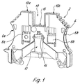
- FIG. 1 shows a protective conductor terminal 2 with a terminal housing 4 made of plastic, which has two lateral openings 6a, 6b for introducing external (not shown here)
- a conductor connection is used 12 with a clamping screw 14, which through an opening 16 in a upper recess 18 of the terminal housing 4 actuated with a screwdriver can be.
- the exact structure of the conductor connection can be seen in FIGS. 2 and 3.
- the Leiteransehluß 12 consists essentially of a busbar piece 20, one Mating bracket 22 and the clamping screw 14.
- the busbar piece 20 is essentially designed as a bent sheet metal part and has at its top in Fig. 2 - facing away from the top-hat rail 9 - one Bend 23 and a seated on this bend 23 (or integrally formed) Connection rail 24, which comprises two side legs 24a, 24b, each are led to the terminal connections 8a, b and the conductor connection 12 with the Connect the terminal connections 8a, b in a conductive manner.
- a push-through opening for the clamping screw 14 is provided in the middle of the connecting bar 24 .
- a web 26 is formed on the bend 23 downwards, on the two outer ones Longitudinal sides in the plane of the web 26 lateral busbar legs 28a, 28b are formed, which protrude at an angle to each other in the plane of the web 26 from this.
- the busbar legs In their end region facing away from the web 26, the busbar legs have 28a, b a first bend 30a, 30b and a second bend 32a, 32b, which essentially describe an angle of 90 °, so that the busbars 28a, b have a type of Z-shaped step 33 in their side view.
- the second bends 32a, 32b of the busbar legs 28a, 28b are on their lower, outer ends with an outer edge running perpendicular to the mounting rail 34a, 34b and guide bevels 36a, 36b.
- the cams 36a, 36b are used for Contacting the outer top-hat rail legs 9a, 9b from above.
- One of the cams the cam 36a sits on the busbar legs 28, respectively.
- the other cam (36b) is formed on the bends 32, respectively.
- the cams 36 are used Contacting the mounting rail 9 from above. Due to the Z-shaped bend, the Cams 36a, 36b laterally offset from one another, which clearly shows the stability of the clamping point elevated.
- the counter plate 22 is also designed as a bent sheet metal part, which is particularly shown in FIG. 3 clarifies.
- the counter-link 22 is parallel aligned to the busbar piece 20 and substantially perpendicular to the top-hat rail 9.
- the threaded bolt is located between the counter plate 22 and the busbar piece 24 14a of the clamping screw 14 in a guide 37 of the counter plate 22.
- Das lower end of the clamping screw facing away from the area of the clamping connections 8a, b 14 is in an opening 38 with an internal thread of a lower bend 40 of the counter link 22 screwable.
- the counter-link 22 also has a central web 42, which extends downward in the Bend 40 ends and on its two long sides in the plane of the web 42 lateral counter-link legs 44a, 44b are integrally formed, which are substantially parallel run to the busbar legs 28a, 28b of the busbar piece 20.
- the Counter-link legs 44a, b are not designed to be angled or Z-shaped but are essentially on a single level.
- the counter link legs 44a, b and the busbar legs 28a, b are initially spaced parallel to each other and contact each other in the area of the to the counter link legs 44a, b aligned bends 30, 32 or the Z-shaped steps 33.
- Hooks 46a, 46b are formed on the outer lower ends of the counter-link plate for gripping under the top-hat rail legs 9a, 9b on the counter-link legs 44a, 44b. These hooks 46a, 46b each have angled portions 48a, 48b, which, at an angle to the top-hat or mounting rail level, run obliquely from the outside inwards and downwards to the top-hat rail legs 9a, 9b.
- the bends 48a, 48b are provided with slots 50a, 50b, in which the bends 32a, 32b of the busbar legs 28a, 28b engage.
- the bends 48a, b therefore form scenes 52a, b for the busbar section 20, which run inclined or obliquely to the top-hat rail.
- a particular advantage of these inclined, V-shaped links 52a, b can be seen in the fact that it is easily possible to use the Stromsehiene Institution from above "into the scenes 52, which was not possible in the prior art with its scenes oriented perpendicularly to the top-hat rail 9, into which lateral projections of the current rail intervened.
- the scenes 52 always ensure a defined guidance of the busbar piece 20 on the counter-link 22.
- Optional inner bends 54 on the inner sides of the hooks 47a, 46b ensure a stable hold of the counter-link 22 on the top-hat rail legs 9a, 9b and also for improved contacting of the top-hat rail 9.
Landscapes
- Engineering & Computer Science (AREA)
- Power Engineering (AREA)
- Connections Arranged To Contact A Plurality Of Conductors (AREA)
- Multi-Conductor Connections (AREA)
- Connector Housings Or Holding Contact Members (AREA)
- Installation Of Bus-Bars (AREA)
Abstract
Description
- Fig. 1
- eine perspektivische Darstellung einer Schutzleiterklemme mit einem erfindungsgemäßen Leiteranschluß;
- Fig 2
- eine Sprengansicht eines erfindungsgemäßen Leiteranschlußes;
- Fig. 3
- eine weitere Sprengansicht des erfindungsgemäßen Leiteranschlußes aus Fig. 2.

- Schutzleiterklemme
- 2
- Klemmengehäuse
- 4
- seitliche Öffnungen
- 6a, 6b
- Klemmanschlüsse
- 8a, 8b
- Hutschiene/Tragschiene
- 9
- Hutschienenschenkel
- 9a, 9b
- Leiteranschluß
- 12
- Klemmschraube
- 14
- Öffnung
- 16
- Ausnehmung
- 18
- Stromschienenstück
- 20
- Gegenlasche
- 22
- Abwinklung
- 23
- Anschlußschiene
- 24
- Schenkel
- 24a, 24b
- Steg
- 26
- Stromschienenschenkel
- 28a, 28b
- erste Abwinklung
- 30a, 30b
- zweite Abwinklung
- 32a, 32b
- Stufung
- 33
- Außenkanten
- 34a, 34b
- Kontaktnocken
- 36a, 36b
- Führung
- 37
- Öffnung
- 38
- Abwinklung
- 40
- Steg
- 42
- Gegenlaschenschenkel
- 44a, 44b
- Haken
- 46a, 46b
- Abwinklungen
- 48a, 48b
- Schlitze
- 50a, 50b
- Kulissen
- 52a, b
- Abwinklungen
- 54
Claims (11)
- Leiteranschluß für eine auf eine Hutschiene (9) mit Hutschienenschenkeln (9a, 9b) aufsetzbare Klemme, insbesondere Leiteranschluß für eine auf eine Hutschiene (9) aufsetzbare Schutzleiterklemme (2), mita) einem auf die Hutschiene (9) aufsetzbaren Stromschienenstück (20);b) einer mit dem Stromschienenstück (20) zusammenwirkenden Gegenlasche (22), welche Mittel (46) zum Untergreifen der Hutschienenschenkel (9a, 9b) aufweist,c) wobei das Stromschienenstück (20) und die Gegenlasche (22) parallelbeweglich aneinander geführt und an der Hutschiene (9) festklemmbar sind,
dadurch gekennzeichnet, daßd) das Stromschienenstück (20) und/oder die Gegenlasche (22) in ihrem gemeinsamen Kontaktbereich wenigstens eine Stufung (33) aufweisen, so daß zwischen dem Stromschienenstück (20) und der Gegenlasche (22) in deren gemeinsamen Kontaktbereich jeweils eine flächige Auflage gebildet wird. - Leiteranschluß nach Anspruch 1 oder nach dem Oberbegriff des Anspruches 1, dadurch gekennzeichnet, daß das Stromschienenstück (20) in wenigstens einer seitlichen Kulisse (52a, 52b) der Gegenlasche (22) geführt ist, welche geneigt zur Hutschiene ausgebildet ist, so daß das Stromschienenstück (20) relativ zur Hutschiene (9) von oben in die Kulissen (52) der Gegenlasche (22) einführbar ist.
- Leiteranschluß nach Anspruch 1 oder 2, dadurch gekennzeichnet, daß die Stufungen (33) im wesentlichen Z-förmig ausgebildet sind.
- Leiteranschluß nach einem der vorstehenden Ansprüche, dadurch gekennzeichnet, daß das Stromschienenstück (20) eine Abwinklung (23) und eine an diese angesetzte oder angeformte Anschlußschiene (24) aufweist.
- Leiteranschluß nach einem der vorstehenden Ansprüche, dadurch gekennzeichnet, daß das Stromschienenstück (20) einen zentralen Steg (26) aufweist, an den zwei äußere Stromschienenschenkel (28a, 28b) angeformt sind.
- Leiteranschluß nach einem der vorstehenden Ansprüche, dadurch gekennzeichnet, daß die Stromschienenschenkel (28a, b) die Z-förmigen Stufungen (33) aufweisen.
- Leiteranschluß nach einem der vorstehenden Ansprüche, dadurch gekennzeichnet, daß die Gegenlasche (22) einen zentralen Steg (42) aufweist, an den seitliche Gegenlaschenschenkel (44a, 44b) angeformt sind, die im wesentlichen parallel zu den Stromschienenschenkeln (28a, 28b) des Stromschienenstückes (20) verlaufen.
- Leiteranschluß nach einem der vorstehenden Ansprüche, dadurch gekennzeichnet, daß die Gegenlaschenschenkel (44a,b) und die Stromschienenschenkel (28a,b) wenigstens abschnittsweise beabstandet parallel zueinander liegen und einander im Bereich der Stufungen (33) kontaktieren.
- Leiteranschluß nach einem der vorstehenden Ansprüche, dadurch gekennzeichnet, daß zwei der Kulissen (52) vorgesehen sind, die jeweils Abwinklungen (48a, 48b) aufweisen, welche geneigt zur Tragschienenebene ausgerichtet und mit Schlitzen (50a, 50b) versehen sind, in welche die Stromschienenschenkel (28a, 28b) eingreifen.
- Leiteranschluß nach einem der vorstehenden Ansprüche, dadurch gekennzeichnet, daß das Stromschienenstück (20) und oder die Gegenlasche (22) im wesentlichen als Blechbiegeteile ausgebildet ist/sind.
- Leiteranschluß nach einem der vorstehenden Ansprüche, dadurch gekennzeichnet, die Stromschienenschenkel (28) und die Abwinklungen (32) jeweils mit zueinander ausgerichteten Kontaktnocken (36a, 36b) versehen sind.
Priority Applications (1)
| Application Number | Priority Date | Filing Date | Title |
|---|---|---|---|
| EP07116782A EP1868265B1 (de) | 1999-08-14 | 2000-05-19 | Leiteranschluß für eine auf eine Hutschiene aufsetzbare Klemme |
Applications Claiming Priority (2)
| Application Number | Priority Date | Filing Date | Title |
|---|---|---|---|
| DE29914290U DE29914290U1 (de) | 1999-08-14 | 1999-08-14 | Leiteranschluß für eine auf eine Hutschiene aufsetzbare Klemme |
| DE29914290U | 1999-08-14 |
Related Child Applications (1)
| Application Number | Title | Priority Date | Filing Date |
|---|---|---|---|
| EP07116782A Division EP1868265B1 (de) | 1999-08-14 | 2000-05-19 | Leiteranschluß für eine auf eine Hutschiene aufsetzbare Klemme |
Publications (2)
| Publication Number | Publication Date |
|---|---|
| EP1077509A1 true EP1077509A1 (de) | 2001-02-21 |
| EP1077509B1 EP1077509B1 (de) | 2007-11-14 |
Family
ID=8077558
Family Applications (2)
| Application Number | Title | Priority Date | Filing Date |
|---|---|---|---|
| EP00110760A Expired - Lifetime EP1077509B1 (de) | 1999-08-14 | 2000-05-19 | Leiteranschluss für eine auf eine Hutschiene aufsetzbare Klemme |
| EP07116782A Expired - Lifetime EP1868265B1 (de) | 1999-08-14 | 2000-05-19 | Leiteranschluß für eine auf eine Hutschiene aufsetzbare Klemme |
Family Applications After (1)
| Application Number | Title | Priority Date | Filing Date |
|---|---|---|---|
| EP07116782A Expired - Lifetime EP1868265B1 (de) | 1999-08-14 | 2000-05-19 | Leiteranschluß für eine auf eine Hutschiene aufsetzbare Klemme |
Country Status (4)
| Country | Link |
|---|---|
| EP (2) | EP1077509B1 (de) |
| AT (2) | ATE378705T1 (de) |
| DE (3) | DE29914290U1 (de) |
| ES (2) | ES2358755T3 (de) |
Families Citing this family (5)
| Publication number | Priority date | Publication date | Assignee | Title |
|---|---|---|---|---|
| DE10218567C5 (de) * | 2002-04-26 | 2010-08-05 | Wieland Electric Gmbh | Anschlusssystem |
| DE10324144B4 (de) * | 2003-05-26 | 2005-09-01 | Phoenix Contact Gmbh & Co. Kg | Elektrische Reihenklemme und metallisches Schutzleiteranschlußelement zur Verwendung in einer elektrischen Reihenklemme |
| DE202010003202U1 (de) | 2010-03-05 | 2010-06-17 | Dehn + Söhne Gmbh + Co. Kg | Montageplatte für elektrische Geräte |
| FR3024599B1 (fr) * | 2014-08-04 | 2016-08-05 | Abb France | Bloc de jonction pour la mise a la terre |
| DE102014115048A1 (de) * | 2014-10-16 | 2016-04-21 | Phoenix Contact Gmbh & Co. Kg | Klemmeneinrichtung mit einer Stromschiene |
Citations (3)
| Publication number | Priority date | Publication date | Assignee | Title |
|---|---|---|---|---|
| US4220392A (en) * | 1978-02-07 | 1980-09-02 | Societe Anonyme Dite: Cgee Alsthom | Terminal block for ground conductors |
| US4269471A (en) * | 1978-08-29 | 1981-05-26 | Oskar Woertz | Electrical terminal for attachment to a contact bar |
| US4776815A (en) * | 1986-01-29 | 1988-10-11 | Legrand | Rail-mounted terminal block |
Family Cites Families (4)
| Publication number | Priority date | Publication date | Assignee | Title |
|---|---|---|---|---|
| DE3117575A1 (de) * | 1981-05-04 | 1982-11-18 | Delta Clip Verbindungstechnik GmbH, 4791 Hövelhof | Schutzleiter-reihenklemme |
| DE3835600A1 (de) * | 1988-10-19 | 1990-05-03 | Wieland Elektrische Industrie | Universal-montagefuss fuer hut- und g-schienen |
| DE4039637A1 (de) * | 1990-12-12 | 1992-06-17 | Weidmueller C A Gmbh Co | Leiteranschluss fuer hutschienen |
| DE4409206C1 (de) * | 1994-03-17 | 1995-05-11 | Phoenix Contact Gmbh & Co | Fuß für eine elektrische Schutzleiterklemme sowie Schutzleiterklemme |
-
1999
- 1999-08-14 DE DE29914290U patent/DE29914290U1/de not_active Expired - Lifetime
-
2000
- 2000-05-19 ES ES07116782T patent/ES2358755T3/es not_active Expired - Lifetime
- 2000-05-19 EP EP00110760A patent/EP1077509B1/de not_active Expired - Lifetime
- 2000-05-19 EP EP07116782A patent/EP1868265B1/de not_active Expired - Lifetime
- 2000-05-19 DE DE50016053T patent/DE50016053D1/de not_active Expired - Lifetime
- 2000-05-19 AT AT00110760T patent/ATE378705T1/de not_active IP Right Cessation
- 2000-05-19 AT AT07116782T patent/ATE493775T1/de active
- 2000-05-19 ES ES00110760T patent/ES2296583T3/es not_active Expired - Lifetime
- 2000-05-19 DE DE50014777T patent/DE50014777D1/de not_active Expired - Lifetime
Patent Citations (3)
| Publication number | Priority date | Publication date | Assignee | Title |
|---|---|---|---|---|
| US4220392A (en) * | 1978-02-07 | 1980-09-02 | Societe Anonyme Dite: Cgee Alsthom | Terminal block for ground conductors |
| US4269471A (en) * | 1978-08-29 | 1981-05-26 | Oskar Woertz | Electrical terminal for attachment to a contact bar |
| US4776815A (en) * | 1986-01-29 | 1988-10-11 | Legrand | Rail-mounted terminal block |
Also Published As
| Publication number | Publication date |
|---|---|
| DE50014777D1 (de) | 2007-12-27 |
| EP1868265B1 (de) | 2010-12-29 |
| DE50016053D1 (de) | 2011-02-10 |
| ATE378705T1 (de) | 2007-11-15 |
| EP1077509B1 (de) | 2007-11-14 |
| ATE493775T1 (de) | 2011-01-15 |
| DE29914290U1 (de) | 2000-12-21 |
| EP1868265A1 (de) | 2007-12-19 |
| ES2358755T3 (es) | 2011-05-13 |
| ES2296583T3 (es) | 2008-05-01 |
Similar Documents
| Publication | Publication Date | Title |
|---|---|---|
| EP3507866B1 (de) | Leiteranschlussklemme | |
| DE3805158A1 (de) | Reihenklemme zur zweileiter-stromversorgung von elektrischen oder elektronischen bauelementen, insbesondere initiatoren | |
| EP0639877B1 (de) | Vorrichtung zum Zuführen elektrischer Energie zu wenigstens einem elektrischen Installationsgerät | |
| EP1100150A1 (de) | Zugfederanschluss für grosse Leiterquerschnitte | |
| EP0010251A1 (de) | Vorrichtung zur Befestigung von Einbau-Installationsgeräten | |
| DE19506056C2 (de) | Adapterplatte zur Anbringung an ein mehrphasiges Stromschienensystem | |
| EP0802583A2 (de) | Erdungsmodul | |
| DE69303065T2 (de) | Verbinderklemme mit Sattel veränderlicher Dicke und mit eingefasster Mutter | |
| EP0075280A2 (de) | Schraubklemme | |
| DE2511385B2 (de) | Elektrische anschlussklemme | |
| DE3804294C1 (de) | ||
| EP0123872A1 (de) | Zenerbarriere | |
| DE2251020B2 (de) | Anschlussvorrichtung | |
| EP0685906A1 (de) | Verfahren zur Herstellung eines Elektrogerätes und nach diesem Verfahren hergestelltes Elektrogerät | |
| EP1868265B1 (de) | Leiteranschluß für eine auf eine Hutschiene aufsetzbare Klemme | |
| EP0821454A1 (de) | Anschlussvorrichtung für elektrische Installationsgeräte | |
| EP1182735B1 (de) | Elektrische Reihenklemme | |
| DE19751705C2 (de) | Verrasteter Einbaublock | |
| EP0336251B1 (de) | Schraubklemme | |
| DE69411294T2 (de) | Anschlussblock für elektrisches Geräte und Leistungsumformer mit einem derartigen Anschlu block | |
| DE29903002U1 (de) | Isoliergehäuse zur Befestigung an einer Tragschiene | |
| DE3723288C2 (de) | ||
| EP0678935B1 (de) | Schutzleiteranschluss an eine hutförmige Tragschiene | |
| DE69617094T2 (de) | Befestigungsvorrichtung für einen Träger eines elektrischen Gerätekastens | |
| DE69904504T2 (de) | Busschienenverbindungsstruktur |
Legal Events
| Date | Code | Title | Description |
|---|---|---|---|
| PUAI | Public reference made under article 153(3) epc to a published international application that has entered the european phase |
Free format text: ORIGINAL CODE: 0009012 |
|
| AK | Designated contracting states |
Kind code of ref document: A1 Designated state(s): AT BE CH CY DE DK ES FI FR GB GR IE IT LI LU MC NL PT SE |
|
| AX | Request for extension of the european patent |
Free format text: AL;LT;LV;MK;RO;SI |
|
| 17P | Request for examination filed |
Effective date: 20010316 |
|
| AKX | Designation fees paid |
Free format text: AT BE CH CY DE DK ES FI FR GB GR IE IT LI LU MC NL PT SE |
|
| GRAP | Despatch of communication of intention to grant a patent |
Free format text: ORIGINAL CODE: EPIDOSNIGR1 |
|
| GRAS | Grant fee paid |
Free format text: ORIGINAL CODE: EPIDOSNIGR3 |
|
| GRAA | (expected) grant |
Free format text: ORIGINAL CODE: 0009210 |
|
| AK | Designated contracting states |
Kind code of ref document: B1 Designated state(s): AT BE CH CY DE DK ES FI FR GB GR IE IT LI LU MC NL PT SE |
|
| REG | Reference to a national code |
Ref country code: GB Ref legal event code: FG4D Free format text: NOT ENGLISH |
|
| REG | Reference to a national code |
Ref country code: CH Ref legal event code: EP |
|
| REG | Reference to a national code |
Ref country code: IE Ref legal event code: FG4D Free format text: LANGUAGE OF EP DOCUMENT: GERMAN |
|
| REF | Corresponds to: |
Ref document number: 50014777 Country of ref document: DE Date of ref document: 20071227 Kind code of ref document: P |
|
| REG | Reference to a national code |
Ref country code: SE Ref legal event code: TRGR |
|
| GBT | Gb: translation of ep patent filed (gb section 77(6)(a)/1977) |
Effective date: 20080207 |
|
| PG25 | Lapsed in a contracting state [announced via postgrant information from national office to epo] |
Ref country code: NL Free format text: LAPSE BECAUSE OF FAILURE TO SUBMIT A TRANSLATION OF THE DESCRIPTION OR TO PAY THE FEE WITHIN THE PRESCRIBED TIME-LIMIT Effective date: 20071114 |
|
| NLV1 | Nl: lapsed or annulled due to failure to fulfill the requirements of art. 29p and 29m of the patents act | ||
| REG | Reference to a national code |
Ref country code: ES Ref legal event code: FG2A Ref document number: 2296583 Country of ref document: ES Kind code of ref document: T3 |
|
| PG25 | Lapsed in a contracting state [announced via postgrant information from national office to epo] |
Ref country code: DK Free format text: LAPSE BECAUSE OF FAILURE TO SUBMIT A TRANSLATION OF THE DESCRIPTION OR TO PAY THE FEE WITHIN THE PRESCRIBED TIME-LIMIT Effective date: 20071114 |
|
| ET | Fr: translation filed | ||
| PLBE | No opposition filed within time limit |
Free format text: ORIGINAL CODE: 0009261 |
|
| STAA | Information on the status of an ep patent application or granted ep patent |
Free format text: STATUS: NO OPPOSITION FILED WITHIN TIME LIMIT |
|
| PG25 | Lapsed in a contracting state [announced via postgrant information from national office to epo] |
Ref country code: PT Free format text: LAPSE BECAUSE OF FAILURE TO SUBMIT A TRANSLATION OF THE DESCRIPTION OR TO PAY THE FEE WITHIN THE PRESCRIBED TIME-LIMIT Effective date: 20080414 |
|
| REG | Reference to a national code |
Ref country code: IE Ref legal event code: FD4D |
|
| 26N | No opposition filed |
Effective date: 20080815 |
|
| PG25 | Lapsed in a contracting state [announced via postgrant information from national office to epo] |
Ref country code: IE Free format text: LAPSE BECAUSE OF FAILURE TO SUBMIT A TRANSLATION OF THE DESCRIPTION OR TO PAY THE FEE WITHIN THE PRESCRIBED TIME-LIMIT Effective date: 20071114 |
|
| BERE | Be: lapsed |
Owner name: WEIDMULLER INTERFACE G.M.B.H. & CO. Effective date: 20080531 |
|
| PG25 | Lapsed in a contracting state [announced via postgrant information from national office to epo] |
Ref country code: MC Free format text: LAPSE BECAUSE OF NON-PAYMENT OF DUE FEES Effective date: 20080531 |
|
| REG | Reference to a national code |
Ref country code: CH Ref legal event code: PL |
|
| PG25 | Lapsed in a contracting state [announced via postgrant information from national office to epo] |
Ref country code: GR Free format text: LAPSE BECAUSE OF FAILURE TO SUBMIT A TRANSLATION OF THE DESCRIPTION OR TO PAY THE FEE WITHIN THE PRESCRIBED TIME-LIMIT Effective date: 20080215 Ref country code: CH Free format text: LAPSE BECAUSE OF NON-PAYMENT OF DUE FEES Effective date: 20080531 Ref country code: LI Free format text: LAPSE BECAUSE OF NON-PAYMENT OF DUE FEES Effective date: 20080531 |
|
| PG25 | Lapsed in a contracting state [announced via postgrant information from national office to epo] |
Ref country code: BE Free format text: LAPSE BECAUSE OF NON-PAYMENT OF DUE FEES Effective date: 20080531 |
|
| PG25 | Lapsed in a contracting state [announced via postgrant information from national office to epo] |
Ref country code: CY Free format text: LAPSE BECAUSE OF FAILURE TO SUBMIT A TRANSLATION OF THE DESCRIPTION OR TO PAY THE FEE WITHIN THE PRESCRIBED TIME-LIMIT Effective date: 20071114 |
|
| PG25 | Lapsed in a contracting state [announced via postgrant information from national office to epo] |
Ref country code: AT Free format text: LAPSE BECAUSE OF NON-PAYMENT OF DUE FEES Effective date: 20080519 |
|
| PG25 | Lapsed in a contracting state [announced via postgrant information from national office to epo] |
Ref country code: FI Free format text: LAPSE BECAUSE OF FAILURE TO SUBMIT A TRANSLATION OF THE DESCRIPTION OR TO PAY THE FEE WITHIN THE PRESCRIBED TIME-LIMIT Effective date: 20071114 |
|
| PG25 | Lapsed in a contracting state [announced via postgrant information from national office to epo] |
Ref country code: LU Free format text: LAPSE BECAUSE OF NON-PAYMENT OF DUE FEES Effective date: 20080519 |
|
| REG | Reference to a national code |
Ref country code: FR Ref legal event code: PLFP Year of fee payment: 17 |
|
| REG | Reference to a national code |
Ref country code: FR Ref legal event code: PLFP Year of fee payment: 18 |
|
| REG | Reference to a national code |
Ref country code: FR Ref legal event code: PLFP Year of fee payment: 19 |
|
| PGFP | Annual fee paid to national office [announced via postgrant information from national office to epo] |
Ref country code: DE Payment date: 20190521 Year of fee payment: 20 Ref country code: IT Payment date: 20190527 Year of fee payment: 20 Ref country code: ES Payment date: 20190620 Year of fee payment: 20 |
|
| PGFP | Annual fee paid to national office [announced via postgrant information from national office to epo] |
Ref country code: FR Payment date: 20190522 Year of fee payment: 20 Ref country code: SE Payment date: 20190521 Year of fee payment: 20 |
|
| PGFP | Annual fee paid to national office [announced via postgrant information from national office to epo] |
Ref country code: GB Payment date: 20190521 Year of fee payment: 20 |
|
| REG | Reference to a national code |
Ref country code: GB Ref legal event code: PE20 Expiry date: 20200518 |
|
| REG | Reference to a national code |
Ref country code: SE Ref legal event code: EUG |
|
| REG | Reference to a national code |
Ref country code: ES Ref legal event code: FD2A Effective date: 20200826 |
|
| PG25 | Lapsed in a contracting state [announced via postgrant information from national office to epo] |
Ref country code: GB Free format text: LAPSE BECAUSE OF EXPIRATION OF PROTECTION Effective date: 20200518 |
|
| PG25 | Lapsed in a contracting state [announced via postgrant information from national office to epo] |
Ref country code: ES Free format text: LAPSE BECAUSE OF EXPIRATION OF PROTECTION Effective date: 20200520 |