EP1077329A1 - Vacuum device - Google Patents
Vacuum device Download PDFInfo
- Publication number
- EP1077329A1 EP1077329A1 EP00906683A EP00906683A EP1077329A1 EP 1077329 A1 EP1077329 A1 EP 1077329A1 EP 00906683 A EP00906683 A EP 00906683A EP 00906683 A EP00906683 A EP 00906683A EP 1077329 A1 EP1077329 A1 EP 1077329A1
- Authority
- EP
- European Patent Office
- Prior art keywords
- vacuum
- gas
- pumps
- pump
- exhaust
- Prior art date
- Legal status (The legal status is an assumption and is not a legal conclusion. Google has not performed a legal analysis and makes no representation as to the accuracy of the status listed.)
- Withdrawn
Links
- 238000010438 heat treatment Methods 0.000 claims description 6
- 238000010521 absorption reaction Methods 0.000 claims 1
- 239000007789 gas Substances 0.000 description 85
- 238000000034 method Methods 0.000 description 12
- 239000004065 semiconductor Substances 0.000 description 12
- 238000004519 manufacturing process Methods 0.000 description 10
- 239000012535 impurity Substances 0.000 description 9
- 238000005530 etching Methods 0.000 description 7
- 239000006227 byproduct Substances 0.000 description 6
- 238000009434 installation Methods 0.000 description 6
- 230000007423 decrease Effects 0.000 description 5
- 229910001220 stainless steel Inorganic materials 0.000 description 4
- 239000010935 stainless steel Substances 0.000 description 4
- 239000000126 substance Substances 0.000 description 4
- 230000000694 effects Effects 0.000 description 3
- 239000004973 liquid crystal related substance Substances 0.000 description 3
- 238000005268 plasma chemical vapour deposition Methods 0.000 description 3
- 239000000758 substrate Substances 0.000 description 3
- 230000003749 cleanliness Effects 0.000 description 2
- 230000006835 compression Effects 0.000 description 2
- 238000007906 compression Methods 0.000 description 2
- 238000012986 modification Methods 0.000 description 2
- 230000004048 modification Effects 0.000 description 2
- 229910021420 polycrystalline silicon Inorganic materials 0.000 description 2
- 229920005591 polysilicon Polymers 0.000 description 2
- XUIMIQQOPSSXEZ-UHFFFAOYSA-N Silicon Chemical compound [Si] XUIMIQQOPSSXEZ-UHFFFAOYSA-N 0.000 description 1
- 230000002411 adverse Effects 0.000 description 1
- 230000015572 biosynthetic process Effects 0.000 description 1
- 239000000919 ceramic Substances 0.000 description 1
- 238000009792 diffusion process Methods 0.000 description 1
- 230000005611 electricity Effects 0.000 description 1
- 239000007792 gaseous phase Substances 0.000 description 1
- 239000000463 material Substances 0.000 description 1
- 238000005259 measurement Methods 0.000 description 1
- 238000001020 plasma etching Methods 0.000 description 1
- 229910052710 silicon Inorganic materials 0.000 description 1
- 239000010703 silicon Substances 0.000 description 1
- 239000007787 solid Substances 0.000 description 1
- 239000007790 solid phase Substances 0.000 description 1
- 239000012265 solid product Substances 0.000 description 1
- 235000012431 wafers Nutrition 0.000 description 1
Images



Classifications
-
- F—MECHANICAL ENGINEERING; LIGHTING; HEATING; WEAPONS; BLASTING
- F04—POSITIVE - DISPLACEMENT MACHINES FOR LIQUIDS; PUMPS FOR LIQUIDS OR ELASTIC FLUIDS
- F04B—POSITIVE-DISPLACEMENT MACHINES FOR LIQUIDS; PUMPS
- F04B37/00—Pumps having pertinent characteristics not provided for in, or of interest apart from, groups F04B25/00 - F04B35/00
- F04B37/10—Pumps having pertinent characteristics not provided for in, or of interest apart from, groups F04B25/00 - F04B35/00 for special use
- F04B37/14—Pumps having pertinent characteristics not provided for in, or of interest apart from, groups F04B25/00 - F04B35/00 for special use to obtain high vacuum
- F04B37/16—Means for nullifying unswept space
-
- F—MECHANICAL ENGINEERING; LIGHTING; HEATING; WEAPONS; BLASTING
- F04—POSITIVE - DISPLACEMENT MACHINES FOR LIQUIDS; PUMPS FOR LIQUIDS OR ELASTIC FLUIDS
- F04D—NON-POSITIVE-DISPLACEMENT PUMPS
- F04D19/00—Axial-flow pumps
- F04D19/02—Multi-stage pumps
- F04D19/04—Multi-stage pumps specially adapted to the production of a high vacuum, e.g. molecular pumps
-
- F—MECHANICAL ENGINEERING; LIGHTING; HEATING; WEAPONS; BLASTING
- F04—POSITIVE - DISPLACEMENT MACHINES FOR LIQUIDS; PUMPS FOR LIQUIDS OR ELASTIC FLUIDS
- F04D—NON-POSITIVE-DISPLACEMENT PUMPS
- F04D25/00—Pumping installations or systems
Definitions
- the present invention relates to vacuum apparatuses, and, more particularly, to a compact vacuum apparatus including vacuum pumps which consume only a small amount of electric power.
- Vacuum apparatuses are used in various industrial fields, such as semiconductor manufacturing and liquid crystal display manufacturing. Particularly in the semiconductor manufacturing and liquid crystal display manufacturing, processes such as film formation and etching are performed in a low-pressure atmosphere in a vacuum apparatus.
- the vacuum apparatus normally includes vacuum pumps so as to maintain a vacuum state or low-pressure state in vacuum containers for performing the processes and measurement.
- the conventional vacuum pumps are roughly divided into a discharge type and a storage type.
- a pump of the discharge type draws a gas in through an inlet and discharges the gas through an exhaust outlet.
- the storage type draws a gas in through an inlet and stores the gas inside the pump.
- a storage-type pump can be evacuated to a point of high vacuum, but the quantity of gas that can be stored is naturally limited. Therefore, in a process that is performed at a reduced pressure with a gas always flowing, a storage-type pump is not suitable, but a discharge-type pump is actually employed.
- a discharge-type pump having a higher ultimate vacuum has a higher exhaust rate and a lower allowable back pressure.
- vacuum pumps that operate in a molecular flow range with a high ultimate vacuum of 1.33 ⁇ 10 -4 Pa (10 -6 Torr) include turbo-molecular pumps, screw pumps, and oil-diffusion pumps. These pumps each have a high exhaust rate, regardless of the size, and a very low allowable back pressure of 133 Pa (1 Torr) or lower.
- Examples of pumps that have low ultimate vacuums and operate at a back pressure substantially equal to atmospheric pressure include Roots pumps, screw pumps,rotary pumps, and diaphragm pumps.
- pumps having medium ultimate vacuums include mechanical booster pumps and executor pumps.
- a vacuum apparatus it is necessary to employ optimum vacuum pumps, depending on a required gas pressure, gas cleanliness, gas flow rate, gas type, vacuum container volume, or the like.
- the gas pressure is as high as 40 Pa (300 mTorr)
- a single pump that operates with a back pressure substantially equal to atmospheric pressure can be employed.
- an exhaust system in which a pump that operates in a molecular flow range and a pump that operates with a back pressure equal to atmospheric pressure are connected in series is employed instead of the single pump.
- a booster pump is interposed between the two pumps, so that the three pumps are connected in series and to exhaust gas.
- a plurality of vacuum containers to be processed are integrally mounted on one device, so that a plurality of cluster tools that can transport substrates between the vacuum containers are aligned.
- one independent exhaust system is provided for each one of the vacuum containers.
- the vacuum containers are in one-to-one correspondence with vacuum pumps, and each of the vacuum pumps evacuates only each corresponding one of the vacuum containers.
- a vacuum pump that operates at a back pressure equal to atmospheric pressure requires a large power for rotating a rotor and consumes much more electric power, compared with a pump that operates at a low back pressure and has the same exhaust rate. Also, such a vacuum pump is large and heavy. In the conventional device, it is necessary to employ such large and power-consuming vacuum pumps in the same number as the number of vacuum containers. As a result, the total power consumption and the installation area of the device are large, and the production costs cannot readily be lowered.
- the exhaust gas discharged from the vacuum containers used for semiconductor production might contain precipitant substances.
- solid substances adhere to the inner walls of the piping lines, and the exhaust conductance of the vacuum apparatus is greatly reduced.
- the principal object of the present invention is to provide a vacuum apparatus that consumes less electric power and has a smaller installation area, and in which a large quantity of gas can flow without impurity gases entering vacuum containers from the exhaust system.
- Another object of the present invention is to provide a vacuum apparatus that has no impurity gases entering into vacuum containers, and can prevent a decrease in exhaust conductance due to a smaller cross-sectional area of a piping line even when the vacuum apparatus is used in a production process in which a precipitant exhaust gas is generated.
- the present Invention provides a vacuum apparatus that comprises a plurality of vacuum containers each having a gas inlet and an exhaust outlet, a gas supply system for introducing a desired gas into each of the vacuum containers through the gas inlet, and an exhaust system for keeping each of the vacuum containers at a low pressure.
- the exhaust system has a plurality of multistage vacuum pumps connected in series; an exhaust outlet pressure of the vacuum pump at a last stage is substantially at atmospheric pressure: and the vacuum pump at the last stage is designed to exhaust gas from the plurality of vacuum containers.
- a common auxiliary pump that evacuates a plurality of vacuum containers at once is added to the atmospheric side of the device so as to maintain the back pressure of the vacuum pump in the previous stage at a low pressure.
- the operational power for the vacuum pumps is reduced, and the power consumption and the size of the vacuum pumps are also greatly reduced. As a result, the power consumption of the entire device and the installation area can be reduced. Thus, the vacuum apparatus can be produced at a lower cost.
- the ultimate vacuum of the vacuum pump in the previous stage can be improved so that impurity gases can be completely prevented from entering the vacuum containers.
- the size the vacuum pump in the previous stage is dramatically reduced, so that the vacuum pump can be placed in the vicinity of the vacuum containers. As a result, a large quantity of gas can flow at a low pressure, and the processing rate and processing efficiency can be greatly increased.
- a removal unit that efficiently removes solid product materials from a precipitant exhaust gas contained in the exhaust gas can further be employed in the vacuum apparatus of the present invention. With such a removal unit, the exhaust conductance in the vacuum apparatus can be maintained in a desired state over a long period of time.
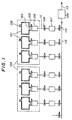
- FIG. 1 shows one embodiment in which a vacuum apparatus of the present invention is applied to a semiconductor processing apparatus.
- Reference numeral 101 indicates vacuum containers, and reference numerals 102 and 103 indicate gas inlets and gas outlets provided for the vacuum containers 101.
- Reference numeral 104 indicates cluster tools each having three vacuum containers integrated on one platform.
- Reference numeral 105 indicates pressure control valves for controlling the gas pressure in the vacuum containers 101.
- Reference numeral 106 indicates high vacuum pumps that are screw molecular pumps in this embodiment.
- Reference numeral 107 indicates low vacuum pumps that are mechanical booster pumps for holding the back pressure of each high vacuum pump 106 low.
- Reference numeral 108 indicates an auxiliary pump that is a Roots pump for holding the back pressure of each low vacuum pump 107.
- Reference numerals 109 and 110 indicate valves that are electromagnetic valves in this embodiment.
- Reference numerals 111, 112, and 113 indicate piping lines for flowing gases.
- the piping line 113 is substantially at atmospheric pressure.
- the gas generated from the auxiliary pump 108 is introduced into a gas processing device through the piping line 113.
- This vacuum apparatus includes 33 cluster tools, i.e., 99 vacuum containers, connected by the piping line 112. However, for simplification of the drawing, only two cluster tools in FIG. 1. In this embodiment, the vacuum containers are used for etching a silicon substrate having a diameter of 200 mm or resist etching.
- gases having a maximum flow rate of 1 atm ⁇ L/min i.e., 1 L/min when calculated in the atmosphere, which is the same in the rest of the specification
- the gases include Ar, CO. C 2 H 6 , and O 2 , among which Ar is the main component.
- a gas having a maximum rate of 1 atm ⁇ L/min at a pressure of 6.67 Pa (50 mTorr) is used.
- the gas includes O 2 . It is necessary to construct an exhaust system that can satisfy the above conditions.
- screw molecular pumps having an exhaust rate of 1,800 L/sec or higher are required to maintain the inlet pressure at 4.00 Pa (30 mTorr) or lower when a gas having an exhaust rate of 1 atm ⁇ L/min flows. Accordingly, screw molecular pumps having an exhaust rate of 2,000 L/sec are employed in this embodiment.
- the back pressure exceeds 53.55 Pa (0.4 Torr) in these screw molecular pumps, the compression ratio is greatly reduced to such a point that the screw molecular pumps cannot function as pumps.
- the inlet pressure is lower than 53.33 Pa (0.4 Torr) when a gas having an exhaust rate of 1 atm ⁇ L/min flows.
- the exhaust rate should be 1,900 L/min or higher, more preferably, 2,000 L/min or higher.
- mechanical booster pumps each having an exhaust rate of 2,000 L/min are employed as the low vacuum pumps 107 in this embodiment.
- a gas having an exhaust rate of 1 atm ⁇ L/min ⁇ 99 9 atm ⁇ L/min flows into this pump if processes are performed simultaneously in all the vacuum containers.
- the allowable back pressure of a mechanical booster pump is 6.67 ⁇ 10 3 (50 Torr). Therefore, the auxiliary pump 108 needs to have an exhaust rate of 1,500 L/min or higher.
- a Roots pump having an exhaust rate of 2,000 L/min is employed as the auxiliary pump 108 in this embodiment.
- each high vacuum pump of this embodiment is 680 W, which is the same as in the prior art, and the total power consumption of 99 vacuum pumps of this embodiment is 68 kW, which is also the same as in the prior art.
- the mechanical booster pumps operate at 1/10 of atmospheric pressure in this embodiment, while pumps such as the Roots pumps operate with a back pressure equal to atmospheric pressure.
- the power consumption of each Roots pump is 3.7 kW, while the power consumption of each mechanical booster pump is 0.4 kW.
- the power consumption of each Roots pump is 9 times as high as the power consumption of each mechanical booster pump. This is because as the back pressure of each pump increases, a larger power is required for rotating the rotor.
- FIG. 2 shows the exhaust characteristics of a mechanical booster pump and Roots pumps.
- Reference numeral 201 indicates the characteristics of the mechanical booster pump having an exhaust rate of 2,000 L/min.
- Reference numeral 202 indicates the characteristics of a Roots pump having an exhaust rate of 2,000 L/min.
- Reference numeral 203 indicates the characteristics of a Roots pump having an exhaust rate of 2,400 L/min.
- the mechanical booster pump operates in a low-pressure region in which the pressure is less than one tenth of the pressure of the Roots pumps.
- As a back pump for a molecular pump it is necessary to employ a pump having a high exhaust rate at a pressure of 133.32 Pa (1 Torr) or lower.
- the exhaust rate is maintained in a low-pressure region of approximately 4.00 Pa (30 mTorr).
- the exhaust rate decreases in a pressure region of 133.32 Pa (1 Torr) or lower. Accordingly, to obtain an exhaust rate necessary for each of the Roots pump, it is necessary to employ larger pumps. For instance, to obtain an exhaust rate of 2,000 L/min at a pressure of 53.33 Pa (0.4 Torr) that is the allowable back pressure of a screw molecular pump, it is necessary to employ a Roots pump having an exhaust rate of 2,400 L/min, as can be seen from FIG. 2.
- the Roots pump has a power consumption 11 times as large as the power consumption of the mechanical booster pump, a volume 14 times as large as the volume of the mechanical booster pump, and a mass 12 times as large as the mass of the mechanical booster pump.
- the power consumption of the Roots pump is 440 kW, while the power consumption of the mechanical booster pump is 40 kW.
- the power consumption of the auxiliary pump is added to the total power consumption.
- the additional power consumption is a very small additional amount to the total power consumption.
- the amount of impurity gases entering into the vacuum containers from the exhaust system is estimated.
- the ultimate pressure of the Roots pumps is 6.00 Pa (45 mTorr), while the ultimate pressure of the mechanical booster pump is 0.53 Pa (4 mTorr).
- the compression ratio of the screw molecular pump is 3000 (with respect to a He gas). Taking only the gas entering from the exhaust system into account, the partial pressure of impurity gases in the vacuum containers is 2.00 ⁇ 10 -3 Pa (1.5 ⁇ 10 -5 Torr) when the Roots pump is used as a back pump, and 1.73 ⁇ 10 -4 Pa (1.3 ⁇ 10 -6 Torr) when the mechanical booster pump is used as a back pump. Accordingly, compared with the prior art, the quantity of the impurity gases entering into the vacuum containers from the exhaust system can be reduced to about one tenth of the quantity of impurity gases entering into the vacuum containers from the exhaust system in the prior art.
- the gas flow rate should be 0.25 atm ⁇ L/min, which is one fourth of 1 atm ⁇ L/min, or lower. This is a principal cause of a decrease in processing rate or performance in the etching or plasma CVD process in which a large quantity of gas needs to flow.
- the low vacuum pumps can be placed in the vicinity of the vacuum containers, because they are very small, in size. The low vacuum pumps and the high vacuum pumps should be connected by short piping lines, so as not to restrict the gas flow rate.
- piping lines 111 0.55-meter long flexible tubes made of stainless steel are used. As described above, the gas conductance of the piping lines is large enough to ignore.
- a stainless-steel straight tube having an inner diameter of 40 mm and a length of 42 m is used. This diameter is not particularly large, but the pressure difference between both ends of the piping line 112 is only 386.63 Pa (2.9 Torr) even when a gas having the maximum gas flow rate of 99 atm ⁇ L/min flows. This pressure difference can be ignored. Accordingly, there is no need to employ a large-diameter piping line. Thus, an increase in piping cost can be prevented.
- the auxiliary pump 108 and the piping line 113 are disposed outside the clean area of the semiconductor fabrication factory, while the other components are disposed within the clean area.
- FIG. 3 shows a second embodiment of the vacuum apparatus of the present invention applied to a semiconductor processing apparatus.
- Reference numeral 301 indicates vacuum containers, and reference numerals 302 and 303 respectively indicate a gas inlet and a gas exhaust outlet formed in each of the vacuum containers 301.
- Reference numeral 304 indicates a cluster tool having three vacuum containers integrated on one platform.
- Reference numeral 305 indicates pressure adjustment valves for controlling the gas pressure in the vacuum containers 301 by changing gas conductance.
- Reference numeral 306 indicates high vacuum pumps that are screw molecular pumps in this embodiment.
- Reference numeral 307 indicates low vacuum pumps for keeping the back pressure of each of the high vacuum pumps 306 at a low value.
- the low vacuum pumps 307 are mechanical booster pumps.
- Reference numeral 308 indicates an auxiliary pump, which is a Roots pump in this embodiment.
- Reference numerals 309 and 310 indicate valves, which are electromagnetic valves in this embodiment.
- Reference numerals 311, 312, and 313 indicate piping lines for flowing gases.
- each of the low vacuum pumps 307 evacuates three vacuum containers in the cluster tool.
- the number of low vacuum pumps 307 can be reduced to one third, and compared with the first embodiment, the power consumption and the device installation area can be reduced.
- the costs for producing the device can be reduced.
- one low vacuum pump evacuates three vacuum containers at the same time in this embodiment
- the number of vacuum containers to be evacuated by one low vacuum pump is not limited to three.
- FIG. 4 shows a third embodiment of the vacuum apparatus of the present invention applied to a semiconductor processing apparatus.
- Reference numerals 401a, 401b, and 401c indicate vacuum containers, and reference numerals 402 and 403 indicate gas inlets and gas exhaust outlets of the vacuum containers 401.
- Reference numeral 404 indicates a cluster tool having three vacuum containers integrated on one platform.
- Reference numeral 405 indicates pressure control valves for controlling the gas pressure in each of the vacuum containers 401 by varying gas conductance.
- Reference numeral 406 indicates a high vacuum pump, which is a screw molecular pump in this embodiment.
- Reference numeral 407 indicates low vacuum pumps, which are mechanical booster pumps in this embodiment.
- Reference numeral 408 indicates an auxiliary pump, which is a Roots pump in this embodiment.
- Reference numerals 409 and 410 indicate valves, which are electromagnetic valves in this embodiment.
- Reference numerals 411, 412, 413, and 414 indicate piping lines for flowing gases.
- the vacuum containers 401a and 401b are plasma CVD devices for polysilicon, and perform processes at a relatively high pressure, for instance, at 53.33 Pa (400 mTorr).
- the vacuum container 401c is an etching device for polysilicon, and performs processes at a low pressure, for instance, at 4.00 Pa (30 mTorr).
- the difference from the first embodiment resides in that the two containers 401a and 401b are not connected to the high vacuum pump in the cluster tool, and are evacuated directly by the low vacuum pumps. Since the processes are performed at a relatively high pressure, for instance, at 53.33 Pa (400 mTorr), a high exhaust efficiency is not required at the low vacuum regions. When processes are performed at a relatively high pressure, no high vacuum pumps are mounted, which reduces the power consumption, the device installation area, and the entire costs.
- FIG. 5 shows a fourth embodiment of the vacuum apparatus of the present invention applied to a semiconductor processing apparatus.
- Reference numeral 501 indicates auxiliary pumps constituted by two Roots pumps each having an exhaust rate of 2000 L/min connected in parallel.
- Reference numerals 502, 503, and 504 indicate valves; more specifically, the valve 502 is an electric valve, and the valves 503 and 504 are manual valves in this embodiment.
- Reference numerals 505 and 506 indicate piping lines for flowing gases. The piping line 506 is substantially at atmospheric pressure.
- one auxiliary pump evacuates a plurality of vacuum containers. As a result, if the auxiliary pump breaks down, all the vacuum containers become unavailable at once.
- the valves 503 and 504 are normally open, and the two auxiliary pumps exhaust gas at the same time. If one of the auxiliary pumps 501 breaks down, the valves 503 and 504, which are located across the broken auxiliary pump 501, are closed, and the broken pump 501 is exchanged for a new one or fixed. During the exchanging or fixing operation, gas is exhausted by the other one of the two auxiliary pumps 501. In this manner, even if one of the auxiliary pumps breaks down, the vacuum apparatus itself can operate properly.
- FIG. 6 shows a fifth embodiment of the vacuum apparatus of the present invention applied to a semiconductor processing apparatus.
- the vacuum apparatus of this embodiment is the same as the vacuum apparatus of the second embodiment, except that a roughing exhaust system is used for evacuating each of the vacuum containers from the atmospheric pressure to a reduced pressure.
- a roughing exhaust system is used for evacuating each of the vacuum containers from the atmospheric pressure to a reduced pressure.
- Reference numeral 601 indicates a roughing pump.
- this roughing pump 601 is a scroll pump having an exhaust rate of 360 L/min.
- the power consumption of the roughing pump 601 is as small as 0.45 kW.
- the roughing pump 601 is also small in size.
- the ultimate vacuum is 1.33 Pa (10 mTorr).
- Reference numerals 602 and 603 indicate valves, which are electric valves in this embodiment.
- Reference numeral 604 indicates piping lines, which are stainless-steel pipes each having a diameter of 9.525 mm (3/8 in.) in this embodiment.
- Reference numeral 605 indicates a piping line that is substantially at atmospheric pressure.
- the corresponding high vacuum pump is stopped, and the corresponding valves 602 and 603 are in the closed state.
- the valve 602 is opened, with the valve 603 remaining in the closed state.
- the air is then discharged by the roughing pump 601 through the piping line 604.
- the valve 602 is closed and the valve 603 is opened.
- the high vacuum pump is then actuated, and the operation returns to the normal operation state.
- two or more vacuum containers are not used at the same time in the cluster tool, so that the entering of gases can be completely prevented compared with the second embodiment by closing the valve 603 of the vacuum container that is not performing the processing and using the roughing pump 601 as a back pump for the high vacuum pumps.
- the cleanliness can be improved.
- This embodiment is achieved by adding the roughing exhaust system to the vacuum apparatus of the second embodiment, but it should be noted that the same effects can be obtained by adding the roughing exhaust system to any one of the foregoing embodiments.
- the piping lines 604 are connected to the exhaust side of the high vacuum pumps in this embodiment, it is also possible to connect the piping lines 604 directly to the vacuum containers or to the exhaust side of the low vacuum pumps.
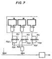
- FIG. 7 shows a sixth embodiment of the vacuum apparatus of the present invention applied to a semiconductor processing apparatus.
- the vacuum apparatus of this embodiment is the same as the vacuum apparatus of the second embodiment, except that a roughing exhaust passage for evacuating each vacuum container from atmospheric pressure to a reduced pressure is employed in the vacuum apparatus of this embodiment. In the following, only the modified aspects will be described.
- Reference numerals 701 and 702 indicate valves, which are electric valves in this embodiment.
- Reference numeral 703 indicates piping lines, which are stainless-steel pipes each having a diameter of 3.175 mm (1/8 in.) in this embodiment.
- the roughing exhaust passage is added to the vacuum apparatus having the same structure as the second embodiment.
- the same effects can be obtained by adding the roughing exhaust passage to any one of the vacuum apparatuses of the first to fourth embodiments.
- FIG. 8 shows a seventh embodiment of the vacuum apparatus of the present invention applied to a semiconductor processing apparatus.
- the vacuum apparatus of this embodiment is the same as the vacuum apparatus of the second embodiment, except that a gas removal unit for removing a part of the gas and a heating unit for heating piping lines between vacuum containers are employed.
- reference numerals 801 and 802 indicate valves each having a heater.
- Reference numerals 803 and 804 indicate piping lines each also having a heater. These piping lines 803 and 804 are covered with a rubber heater 809, and are thus maintained constantly at 90 °C or higher when the vacuum apparatus is used.
- Reference numerals 805 and 806 indicate normal piping lines.
- Reference numeral 807 is a water-cooled trap.
- Reference numeral 808 indicates an auxiliary pump equivalent to the auxiliary pump 308 of the second embodiment shown in FIG. 3.
- a large amount of precipitant by-products is contained in an exhausted gas generated after processing in a vacuum container. These by-products are contained in the gaseous phase components and exhaust gas in the vacuum containers. As the by-products are cooled through the piping lines, they turn into solid phase components and might adhere to the inner walls of the piping lines. Such an adhering substance causes a decrease in exhaust performance of the vacuum pumps and a failure of the device itself. Such an adhering substance also reduces the cross-sectional area of each piping line, and thus reduces the exhaust conductance. Therefore, it is preferable to take suitable measures to prevent the adhesion of the precipitant by-products.
- the water-cooled trap 807 for removing the gaseous components, which cause the adhesion is employed. Further, by heating the piping lines leading to the water-cooled trap 807 to such a temperature that causes no adhesion, no by-products adhere to the inner walls of the piping lines leading to the water-cooled trap 807.
- the heating unit may be any type of heater, such as a ceramic heater, as long as it can heat the contact portion with the exhaust gas in the exhaust passage to 90 °C or higher. Accordingly, the heating unit that can be employed in this embodiment is not limited to the rubber heater of this embodiment.
- This embodiment is a modification of the vacuum apparatus of the second embodiment, but it should be noted that the same effects can be obtained by making the same modification to any one of the foregoing embodiments.
- the vacuum apparatus that consumes less electricity and has a smaller installation area can be obtained.
- this vacuum apparatus no impurity gas is introduced into the vacuum containers from the exhaust system, and a large quantity of gas can flow throughout the device.
- the exhaust conductance in the vacuum apparatus of the present invention can be maintained in a desired state over a long period of time.
Landscapes
- Engineering & Computer Science (AREA)
- Mechanical Engineering (AREA)
- General Engineering & Computer Science (AREA)
- Compressors, Vaccum Pumps And Other Relevant Systems (AREA)
- Drying Of Semiconductors (AREA)
Abstract
The present invention provides a vacuum
apparatus that includes a plurality of vacuum containers
each having a gas inlet and an exhaust outlet, a gas
supply system for introducing a desired gas into each of
the vacuum containers through the gas inlet, and an
exhaust system for keeping each of the vacuum containers
at a low pressure. In this vacuum apparatus, the exhaust
system includes a plurality of multistage vacuum pumps
connected in series. The exhaust outlet pressure of the
last-stage vacuum pump is substantially at atmospheric
pressure. The last-stage vacuum pump is designed to
exhaust gas from a plurality of vacuum pumps at previous
stages.
Description
The present invention relates to vacuum
apparatuses, and, more particularly, to a compact vacuum
apparatus including vacuum pumps which consume only a
small amount of electric power.
Vacuum apparatuses are used in various
industrial fields, such as semiconductor manufacturing and
liquid crystal display manufacturing. Particularly in the
semiconductor manufacturing and liquid crystal display
manufacturing, processes such as film formation and
etching are performed in a low-pressure atmosphere in a
vacuum apparatus. The vacuum apparatus normally includes
vacuum pumps so as to maintain a vacuum state or low-pressure
state in vacuum containers for performing the
processes and measurement.
The conventional vacuum pumps are roughly
divided into a discharge type and a storage type. A pump
of the discharge type draws a gas in through an inlet and
discharges the gas through an exhaust outlet. The storage
type draws a gas in through an inlet and stores the gas
inside the pump. Generally, a storage-type pump can be
evacuated to a point of high vacuum, but the quantity of
gas that can be stored is naturally limited. Therefore,
in a process that is performed at a reduced pressure with
a gas always flowing, a storage-type pump is not suitable,
but a discharge-type pump is actually employed.
Generally, a discharge-type pump having a higher
ultimate vacuum has a higher exhaust rate and a lower
allowable back pressure. Examples of vacuum pumps that
operate in a molecular flow range with a high ultimate
vacuum of 1.33 × 10⁻⁴ Pa (10-6 Torr) include turbo-molecular
pumps, screw pumps, and oil-diffusion pumps.
These pumps each have a high exhaust rate, regardless of
the size, and a very low allowable back pressure of 133 Pa
(1 Torr) or lower. Examples of pumps that have low
ultimate vacuums and operate at a back pressure
substantially equal to atmospheric pressure include Roots
pumps, screw pumps,rotary pumps, and diaphragm pumps.
Examples of pumps having medium ultimate vacuums include
mechanical booster pumps and executor pumps.
In a vacuum apparatus, it is necessary to employ
optimum vacuum pumps, depending on a required gas pressure,
gas cleanliness, gas flow rate, gas type, vacuum container
volume, or the like. Generally, if the gas pressure is as
high as 40 Pa (300 mTorr), a single pump that operates
with a back pressure substantially equal to atmospheric
pressure can be employed. On the other hand, if the gas
pressure is low, an exhaust system in which a pump that
operates in a molecular flow range and a pump that
operates with a back pressure equal to atmospheric
pressure are connected in series is employed instead of
the single pump. If the gas flow rate is high, a booster
pump is interposed between the two pumps, so that the
three pumps are connected in series and to exhaust gas.
In a mass-production factory of semiconductors
or liquid-crystal displays, most of the processes required
for production are performed at a reduced pressure. In
such a case, a plurality of vacuum containers to be
processed are integrally mounted on one device, so that a
plurality of cluster tools that can transport substrates
between the vacuum containers are aligned. This means
that, generally, a plurality of vacuum containers are
arranged together. In a conventional device, one
independent exhaust system is provided for each one of the
vacuum containers. The vacuum containers are in one-to-one
correspondence with vacuum pumps, and each of the
vacuum pumps evacuates only each corresponding one of the
vacuum containers.
A vacuum pump that operates at a back pressure
equal to atmospheric pressure requires a large power for
rotating a rotor and consumes much more electric power,
compared with a pump that operates at a low back pressure
and has the same exhaust rate. Also, such a vacuum pump
is large and heavy. In the conventional device, it is
necessary to employ such large and power-consuming vacuum
pumps in the same number as the number of vacuum
containers. As a result, the total power consumption and
the installation area of the device are large, and the
production costs cannot readily be lowered.
Furthermore, since a vacuum pump that operates
at a back pressure equal to atmospheric pressure has a
lower ultimate vacuum on the suction side, there is a
problem that, once an impurity gas adheres to the surfaces
of wafers or the inner surfaces of the vacuum containers,
the processing performance drastically deteriorates. Also,
it is often difficult to place such pumps in the vicinity
of the vacuum containers, because these pumps are too
large in size. Therefore, the vacuum pumps need to be
connected by long piping lines. This is a main reason for
a decrease in processing rate or processing efficiency in
a process that requires a large quantity of flow gas.
Also, the exhaust gas discharged from the vacuum
containers used for semiconductor production might contain
precipitant substances. As a result, solid substances
adhere to the inner walls of the piping lines, and the
exhaust conductance of the vacuum apparatus is greatly
reduced.
In view of the above problems, the principal
object of the present invention is to provide a vacuum
apparatus that consumes less electric power and has a
smaller installation area, and in which a large quantity
of gas can flow without impurity gases entering vacuum
containers from the exhaust system. Another object of the
present invention is to provide a vacuum apparatus that
has no impurity gases entering into vacuum containers, and
can prevent a decrease in exhaust conductance due to a
smaller cross-sectional area of a piping line even when
the vacuum apparatus is used in a production process in
which a precipitant exhaust gas is generated.
To achieve the above objects, the present
Invention provides a vacuum apparatus that comprises a
plurality of vacuum containers each having a gas inlet and
an exhaust outlet, a gas supply system for introducing a
desired gas into each of the vacuum containers through the
gas inlet, and an exhaust system for keeping each of the
vacuum containers at a low pressure. In this vacuum
apparatus, the exhaust system has a plurality of
multistage vacuum pumps connected in series; an exhaust
outlet pressure of the vacuum pump at a last stage is
substantially at atmospheric pressure: and the vacuum pump
at the last stage is designed to exhaust gas from the
plurality of vacuum containers.
In the vacuum apparatus of the present invention,
a common auxiliary pump that evacuates a plurality of
vacuum containers at once is added to the atmospheric side
of the device so as to maintain the back pressure of the
vacuum pump in the previous stage at a low pressure.
Compared with the prior art in which the back pressure is
atmospheric pressure, the operational power for the vacuum
pumps is reduced, and the power consumption and the size
of the vacuum pumps are also greatly reduced. As a result,
the power consumption of the entire device and the
installation area can be reduced. Thus, the vacuum
apparatus can be produced at a lower cost.
Also, the ultimate vacuum of the vacuum pump in
the previous stage can be improved so that impurity gases
can be completely prevented from entering the vacuum
containers. Furthermore, the size the vacuum pump in the
previous stage is dramatically reduced, so that the vacuum
pump can be placed in the vicinity of the vacuum
containers. As a result, a large quantity of gas can flow
at a low pressure, and the processing rate and processing
efficiency can be greatly increased.
A removal unit that efficiently removes solid
product materials from a precipitant exhaust gas contained
in the exhaust gas can further be employed in the vacuum
apparatus of the present invention. With such a removal
unit, the exhaust conductance in the vacuum apparatus can
be maintained in a desired state over a long period of
time.
The following is a description of embodiments of
vacuum apparatuses of the present invention, with
reference to the accompanying drawings. It should be
understood that the present invention is not limited to
the embodiments described below.
FIG. 1 shows one embodiment in which a vacuum
apparatus of the present invention is applied to a
semiconductor processing apparatus.
In the high-speed and high-performance etching
of the substrate having the diameter of 200 mm, gases
having a maximum flow rate of 1 atm · L/min (i.e., 1 L/min
when calculated in the atmosphere, which is the same in
the rest of the specification) at a pressure of
approximately 4.00 Pa (30 mTorr) are used. The gases
include Ar, CO. C2H6, and O2, among which Ar is the main
component. In the high-speed etching process, a gas
having a maximum rate of 1 atm · L/min at a pressure of
6.67 Pa (50 mTorr) is used. The gas includes O2. It is
necessary to construct an exhaust system that can satisfy
the above conditions.
As for the high vacuum pumps 106, screw
molecular pumps having an exhaust rate of 1,800 L/sec or
higher are required to maintain the inlet pressure at 4.00
Pa (30 mTorr) or lower when a gas having an exhaust rate
of 1 atm · L/min flows. Accordingly, screw molecular pumps
having an exhaust rate of 2,000 L/sec are employed in this
embodiment. When the back pressure exceeds 53.55 Pa (0.4
Torr) in these screw molecular pumps, the compression
ratio is greatly reduced to such a point that the screw
molecular pumps cannot function as pumps. As for the low
vacuum pumps 107, the inlet pressure is lower than 53.33
Pa (0.4 Torr) when a gas having an exhaust rate of 1 atm ·
L/min flows. Accordingly, the exhaust rate should be
1,900 L/min or higher, more preferably, 2,000 L/min or
higher. For this reason, mechanical booster pumps each
having an exhaust rate of 2,000 L/min are employed as the
low vacuum pumps 107 in this embodiment. As for the
auxiliary pump 108, a gas having an exhaust rate of 1
atm · L/min × 99 = 9 atm · L/min flows into this pump if
processes are performed simultaneously in all the vacuum
containers. The allowable back pressure of a mechanical
booster pump is 6.67 × 10³ (50 Torr). Therefore, the
auxiliary pump 108 needs to have an exhaust rate of 1,500
L/min or higher. Taking the gas conductance of the piping
line 112 into account, a Roots pump having an exhaust rate
of 2,000 L/min is employed as the auxiliary pump 108 in
this embodiment.
Compared with the prior art, the power
consumption of each high vacuum pump of this embodiment is
680 W, which is the same as in the prior art, and the
total power consumption of 99 vacuum pumps of this
embodiment is 68 kW, which is also the same as in the
prior art.
As for the low vacuum pumps, the mechanical
booster pumps operate at 1/10 of atmospheric pressure in
this embodiment, while pumps such as the Roots pumps
operate with a back pressure equal to atmospheric pressure.
A comparison is now made between the Roots pumps and the
mechanical pumps each having an exhaust rate of 2,000
L/min. The power consumption of each Roots pump is 3.7 kW,
while the power consumption of each mechanical booster
pump is 0.4 kW. Despite the same exhaust rate as each
mechanical booster pump, the power consumption of each
Roots pump is 9 times as high as the power consumption of
each mechanical booster pump. This is because as the back
pressure of each pump increases, a larger power is
required for rotating the rotor. The volume of each Roots
pump is 0.95 × 0.42 × 0.55 m3 = 0.22 m3. The volume of
each mechanical booster pump is 0.48 × 0.21 × 0.18 m3 =
0.018 m3. Accordingly, the volume of each Roots pump is
12 times as large as the volume of each mechanical booster
pump. The mass of each Roots pump is 223 kg, while the
mass of each mechanical booster pump is 22 kg. The mass
of each Roots pump is 10 times larger than the mass of
each mechanical booster pump. Accordingly, the mechanical
booster pumps that operate at a low back pressure are much
smaller and consume much less electric power. Furthermore,
the mechanical booster pumps have simpler structures, and
are less expensive.
FIG. 2 shows the exhaust characteristics of a
mechanical booster pump and Roots pumps. Reference
numeral 201 indicates the characteristics of the
mechanical booster pump having an exhaust rate of 2,000
L/min. Reference numeral 202 indicates the
characteristics of a Roots pump having an exhaust rate of
2,000 L/min. Reference numeral 203 indicates the
characteristics of a Roots pump having an exhaust rate of
2,400 L/min. As can be seen from FIG. 2, the mechanical
booster pump operates in a low-pressure region in which
the pressure is less than one tenth of the pressure of the
Roots pumps. As a back pump for a molecular pump, it is
necessary to employ a pump having a high exhaust rate at a
pressure of 133.32 Pa (1 Torr) or lower. For the
mechanical booster pump, the exhaust rate is maintained in
a low-pressure region of approximately 4.00 Pa (30 mTorr).
For each of the Roots pumps, the exhaust rate decreases in
a pressure region of 133.32 Pa (1 Torr) or lower.
Accordingly, to obtain an exhaust rate necessary for each
of the Roots pump, it is necessary to employ larger pumps.
For instance, to obtain an exhaust rate of 2,000 L/min at
a pressure of 53.33 Pa (0.4 Torr) that is the allowable
back pressure of a screw molecular pump, it is necessary
to employ a Roots pump having an exhaust rate of 2,400
L/min, as can be seen from FIG. 2. As a result of a
comparison between the mechanical booster pump having an
exhaust rate of 2,000 L/min and the Roots pump having an
exhaust rate of 2,400 L/min, it was found that the Roots
pump has a power consumption 11 times as large as the
power consumption of the mechanical booster pump, a volume
14 times as large as the volume of the mechanical booster
pump, and a mass 12 times as large as the mass of the
mechanical booster pump. With 99 low vacuum pumps, the
power consumption of the Roots pump is 440 kW, while the
power consumption of the mechanical booster pump is 40 kW.
In this embodiment, the power consumption of the
auxiliary pump is added to the total power consumption.
However, since a number of vacuum containers are evacuated
by only the one auxiliary pump, the additional power
consumption is a very small additional amount to the total
power consumption. The total power consumption of all the
vacuum pumps is 68 kW + 440 kW = 508 kW in the prior art,
but 68 kW + 40 kW + 3.7 kW = 111.7 kW in this embodiment.
Accordingly, the power consumption can be reduced to 22 %
of the power consumption in the prior art.
Next, when no gases are flowing through the
vacuum containers, the amount of impurity gases entering
into the vacuum containers from the exhaust system is
estimated. As can be seen from FIG. 2, the ultimate
pressure of the Roots pumps is 6.00 Pa (45 mTorr), while
the ultimate pressure of the mechanical booster pump is
0.53 Pa (4 mTorr). The compression ratio of the screw
molecular pump is 3000 (with respect to a He gas). Taking
only the gas entering from the exhaust system into account,
the partial pressure of impurity gases in the vacuum
containers is 2.00 × 10⁻³ Pa (1.5 × 10⁻⁵ Torr) when the
Roots pump is used as a back pump, and 1.73 × 10⁻⁴ Pa (1.3
× 10-6 Torr) when the mechanical booster pump is used as a
back pump. Accordingly, compared with the prior art, the
quantity of the impurity gases entering into the vacuum
containers from the exhaust system can be reduced to about
one tenth of the quantity of impurity gases entering into
the vacuum containers from the exhaust system in the prior
art.
In a conventional vacuum apparatus, it is often
difficult to dispose low vacuum pumps in the vicinity of
the vacuum containers, because of the large size of each
low vacuum pump. Therefore, long piping lines are
necessary to connect the low vacuum pumps and the high
vacuum pumps. As a result of this, when a large quantity
of gas flows, the back pressure of the high vacuum pumps
rises due to an influence of the gas conductance of the
piping lines. For instance, when a gas having an exhaust
rate of 1 atm · L/min flows, the pressure is 53.33 Pa (0.4
Torr) without piping lines. However, with a 10-meter long
cylindrical piping line, the pressure is 11.99 Pa (0.84
Torr). To maintain the back pressure of the high vacuum
pumps at 53.33 Pa (0.4 Torr) or lower, the gas flow rate
should be 0.25 atm · L/min, which is one fourth of 1 atm ·
L/min, or lower. This is a principal cause of a decrease
in processing rate or performance in the etching or plasma
CVD process in which a large quantity of gas needs to flow.
In this embodiment, on the other hand, the low vacuum
pumps can be placed in the vicinity of the vacuum
containers, because they are very small, in size. The low
vacuum pumps and the high vacuum pumps should be connected
by short piping lines, so as not to restrict the gas flow
rate.
For the piping lines 111, 0.55-meter long
flexible tubes made of stainless steel are used. As
described above, the gas conductance of the piping lines
is large enough to ignore. For the piping line 112, a
stainless-steel straight tube having an inner diameter of
40 mm and a length of 42 m is used. This diameter is not
particularly large, but the pressure difference between
both ends of the piping line 112 is only 386.63 Pa (2.9
Torr) even when a gas having the maximum gas flow rate of
99 atm · L/min flows. This pressure difference can be
ignored. Accordingly, there is no need to employ a large-diameter
piping line. Thus, an increase in piping cost
can be prevented.
The auxiliary pump 108 and the piping line 113
are disposed outside the clean area of the semiconductor
fabrication factory, while the other components are
disposed within the clean area.
FIG. 3 shows a second embodiment of the vacuum
apparatus of the present invention applied to a
semiconductor processing apparatus.
The difference from the first embodiment resides
in that each of the low vacuum pumps 307 evacuates three
vacuum containers in the cluster tool. By sharing each of
the low vacuum pumps 307 in this manner, the number of low
vacuum pumps 307 can be reduced to one third, and compared
with the first embodiment, the power consumption and the
device installation area can be reduced. Thus, the costs
for producing the device can be reduced.
Although one low vacuum pump evacuates three
vacuum containers at the same time in this embodiment, the
number of vacuum containers to be evacuated by one low
vacuum pump is not limited to three.
FIG. 4 shows a third embodiment of the vacuum
apparatus of the present invention applied to a
semiconductor processing apparatus.
The vacuum containers 401a and 401b are plasma
CVD devices for polysilicon, and perform processes at a
relatively high pressure, for instance, at 53.33 Pa (400
mTorr). The vacuum container 401c is an etching device
for polysilicon, and performs processes at a low pressure,
for instance, at 4.00 Pa (30 mTorr). The difference from
the first embodiment resides in that the two containers
401a and 401b are not connected to the high vacuum pump in
the cluster tool, and are evacuated directly by the low
vacuum pumps. Since the processes are performed at a
relatively high pressure, for instance, at 53.33 Pa (400
mTorr), a high exhaust efficiency is not required at the
low vacuum regions. When processes are performed at a
relatively high pressure, no high vacuum pumps are mounted,
which reduces the power consumption, the device
installation area, and the entire costs.
FIG. 5 shows a fourth embodiment of the vacuum
apparatus of the present invention applied to a
semiconductor processing apparatus.
In FIG. 5, only the differences from the first
embodiment are shown. Reference numeral 501 indicates
auxiliary pumps constituted by two Roots pumps each having
an exhaust rate of 2000 L/min connected in parallel.
Reference numerals 502, 503, and 504 indicate valves; more
specifically, the valve 502 is an electric valve, and the
valves 503 and 504 are manual valves in this embodiment.
Reference numerals 505 and 506 indicate piping lines for
flowing gases. The piping line 506 is substantially at
atmospheric pressure.
In the foregoing embodiments, one auxiliary pump
evacuates a plurality of vacuum containers. As a result,
if the auxiliary pump breaks down, all the vacuum
containers become unavailable at once. In this embodiment,
on the other hand, the valves 503 and 504 are normally
open, and the two auxiliary pumps exhaust gas at the same
time. If one of the auxiliary pumps 501 breaks down, the
valves 503 and 504, which are located across the broken
auxiliary pump 501, are closed, and the broken pump 501 is
exchanged for a new one or fixed. During the exchanging
or fixing operation, gas is exhausted by the other one of
the two auxiliary pumps 501. In this manner, even if one
of the auxiliary pumps breaks down, the vacuum apparatus
itself can operate properly.
FIG. 6 shows a fifth embodiment of the vacuum
apparatus of the present invention applied to a
semiconductor processing apparatus. The vacuum apparatus
of this embodiment is the same as the vacuum apparatus of
the second embodiment, except that a roughing exhaust
system is used for evacuating each of the vacuum
containers from the atmospheric pressure to a reduced
pressure. In the following, only the modified aspects
will be described.
When a vacuum container is maintained, the
vacuum container needs to be aired out. When the vacuum
containers are evacuated again, a large quantity of air
might flow into the exhaust system, and the back pressure
of the low vacuum pumps might go up, resulting in an
adverse influence on the other vacuum containers. This
problem is to be solved by further employing a roughing
exhaust system in this embodiment.
When a vacuum container is aired out, the
corresponding high vacuum pump is stopped, and the
corresponding valves 602 and 603 are in the closed state.
When the vacuum container is evacuated again, the valve
602 is opened, with the valve 603 remaining in the closed
state. The air is then discharged by the roughing pump
601 through the piping line 604. After that, at a point
where the inner pressure of the vacuum container has been
reduced to a degree in a range of 2,666 to 7,999 Pa (10
Torr or higher), the valve 602 is closed and the valve 603
is opened. The high vacuum pump is then actuated, and the
operation returns to the normal operation state.
In this embodiment, two or more vacuum
containers are not used at the same time in the cluster
tool, so that the entering of gases can be completely
prevented compared with the second embodiment by closing
the valve 603 of the vacuum container that is not
performing the processing and using the roughing pump 601
as a back pump for the high vacuum pumps. Thus, the
cleanliness can be improved.
This embodiment is achieved by adding the
roughing exhaust system to the vacuum apparatus of the
second embodiment, but it should be noted that the same
effects can be obtained by adding the roughing exhaust
system to any one of the foregoing embodiments. Although
the piping lines 604 are connected to the exhaust side of
the high vacuum pumps in this embodiment, it is also
possible to connect the piping lines 604 directly to the
vacuum containers or to the exhaust side of the low vacuum
pumps.
FIG. 7 shows a sixth embodiment of the vacuum
apparatus of the present invention applied to a
semiconductor processing apparatus. The vacuum apparatus
of this embodiment is the same as the vacuum apparatus of
the second embodiment, except that a roughing exhaust
passage for evacuating each vacuum container from
atmospheric pressure to a reduced pressure is employed in
the vacuum apparatus of this embodiment. In the following,
only the modified aspects will be described.
When a vacuum container is opened to the air,
the corresponding high vacuum pump is stopped, and the
corresponding valves 701 and 702 are in the closed state.
When the vacuum container is evacuated again, the valve
701 is opened, with the valve 702 remaining in the closed
state, The air is then discharged by the low vacuum pump
through the piping line 703. Since the piping line 703
has a small inner diameter and a small gas conductance,
the flow rate of the gas flowing into the low vacuum pump
is restricted, so as to restrain an increase in back
pressure of the low vacuum pump. After that, at a point
where the inner pressure of the vacuum container has been
reduced to a degree in the range of 2,666 to 7,999 Pa (10
Torr or higher), the valve 701 is closed and the valve 702
is opened. The high vacuum pump is then activated, and
the operation returns to the normal operation state.
In this embodiment, the roughing exhaust passage
is added to the vacuum apparatus having the same structure
as the second embodiment. However, it should be noted
that the same effects can be obtained by adding the
roughing exhaust passage to any one of the vacuum
apparatuses of the first to fourth embodiments.
FIG. 8 shows a seventh embodiment of the vacuum
apparatus of the present invention applied to a
semiconductor processing apparatus. The vacuum apparatus
of this embodiment is the same as the vacuum apparatus of
the second embodiment, except that a gas removal unit for
removing a part of the gas and a heating unit for heating
piping lines between vacuum containers are employed.
In FIG. 8, reference numerals 801 and 802
indicate valves each having a heater. Reference numerals
803 and 804 indicate piping lines each also having a
heater. These piping lines 803 and 804 are covered with a
rubber heater 809, and are thus maintained constantly at
90 °C or higher when the vacuum apparatus is used.
Reference numerals 805 and 806 indicate normal piping
lines. Reference numeral 807 is a water-cooled trap.
Reference numeral 808 indicates an auxiliary pump
equivalent to the auxiliary pump 308 of the second
embodiment shown in FIG. 3.
In a plasma CVD apparatus or a plasma etching
apparatus, a large amount of precipitant by-products is
contained in an exhausted gas generated after processing
in a vacuum container. These by-products are contained in
the gaseous phase components and exhaust gas in the vacuum
containers. As the by-products are cooled through the
piping lines, they turn into solid phase components and
might adhere to the inner walls of the piping lines. Such
an adhering substance causes a decrease in exhaust
performance of the vacuum pumps and a failure of the
device itself. Such an adhering substance also reduces
the cross-sectional area of each piping line, and thus
reduces the exhaust conductance. Therefore, it is
preferable to take suitable measures to prevent the
adhesion of the precipitant by-products.
In this embodiment, the water-cooled trap 807
for removing the gaseous components, which cause the
adhesion, is employed. Further, by heating the piping
lines leading to the water-cooled trap 807 to such a
temperature that causes no adhesion, no by-products adhere
to the inner walls of the piping lines leading to the
water-cooled trap 807.
Although the water-cooled trap 807 is employed
to remove the precipitant components in the exhaust gas in
this embodiment, other suitable devices can be employed.
Also, the heating unit may be any type of heater, such as
a ceramic heater, as long as it can heat the contact
portion with the exhaust gas in the exhaust passage to
90 °C or higher. Accordingly, the heating unit that can
be employed in this embodiment is not limited to the
rubber heater of this embodiment.
This embodiment is a modification of the vacuum
apparatus of the second embodiment, but it should be noted
that the same effects can be obtained by making the same
modification to any one of the foregoing embodiments.
As described so far, according to the present
invention, the vacuum apparatus that consumes less
electricity and has a smaller installation area can be
obtained. In this vacuum apparatus, no impurity gas is
introduced into the vacuum containers from the exhaust
system, and a large quantity of gas can flow throughout
the device.
Furthermore, with the removal unit for removing
precipitant by-products contained in the exhaust gas, the
exhaust conductance in the vacuum apparatus of the present
invention can be maintained in a desired state over a long
period of time.
Claims (8)
- A vacuum apparatus that comprises a plurality of vacuum containers each having a gas inlet and an exhaust outlet, a gas supply system for introducing a desired gas into each of the vacuum containers through the gas inlet, and an exhaust system for keeping each of the vacuum containers at a low pressure,
said device characterized in that:the exhaust system has a plurality of multistage vacuum pumps connected in series;an exhaust outlet pressure of the vacuum pump at a last stage is substantially at atmospheric pressure; andthe vacuum pump at the last stage is designed to exhaust gas from the plurality of vacuum containers. - A vacuum apparatus that comprises a plurality of vacuum containers each having a gas inlet and an exhaust outlet, a gas supply system for introducing a desired gas into each of the vacuum containers through the gas inlet, and an exhaust system for keeping each of the vacuum containers at a low pressure,
said device characterized in that:the exhaust system includes initial stage vacuum pumps each connected to each corresponding exhaust outlet of the vacuum containers, intermediate stage vacuum pumps connected on a downstream side of the initial stage vacuum pumps, and a latter stage vacuum pump connected on a downstream side of the intermediate vacuum pumps;an exhaust outlet pressure of the latter vacuum pump is substantially at atmospheric pressure; andthe latter stage vacuum pump is designed to exhaust gas from a plurality of the intermediate stage vacuum pumps. - The vacuum apparatus as claimed in claim 2, wherein at least one of the intermediate vacuum pumps is designed to exhaust gas from a plurality of the initial stage vacuum pumps.
- The vacuum apparatus as claimed in one of claims 1 to 3, wherein:roughing vacuum pumps are connected to the exhaust outlet of each of the vacuum containers or on a downstream side of each vacuum pump connected to each corresponding exhaust outlet of the vacuum containers, so as to evacuate each of the vacuum containers; andan exhaust inlet pressure of the roughing vacuum pump is substantially at atmospheric pressure.
- The vacuum apparatus as claimed in one of claims 1 to 4, wherein a plurality of last stage vacuum pumps are arranged in parallel.
- The vacuum apparatus as claimed in one of claims 1 to 5, wherein a gas removal means that removes a part of the gas is disposed between each last stage vacuum pump and a previous stage vacuum pump.
- The vacuum apparatus as claimed in claim 6, further comprising a heating means that heats a gas contact portion to 90°C or higher in a gas exhaust passage between each vacuum container and the gas removal means.
- The vacuum apparatus as claimed one of claims 1 to 7, wherein an absorption inlet ultimate pressure of the last stage vacuum pump is 6.67 × 10³ Pa (50 Torr) or less.
Applications Claiming Priority (3)
| Application Number | Priority Date | Filing Date | Title |
|---|---|---|---|
| JP10303899 | 1999-03-05 | ||
| JP10303899 | 1999-03-05 | ||
| PCT/JP2000/001292 WO2000053928A1 (en) | 1999-03-05 | 2000-03-03 | Vacuum device |
Publications (2)
| Publication Number | Publication Date |
|---|---|
| EP1077329A1 true EP1077329A1 (en) | 2001-02-21 |
| EP1077329A4 EP1077329A4 (en) | 2006-08-02 |
Family
ID=14343505
Family Applications (1)
| Application Number | Title | Priority Date | Filing Date |
|---|---|---|---|
| EP00906683A Withdrawn EP1077329A4 (en) | 1999-03-05 | 2000-03-03 | Vacuum device |
Country Status (6)
| Country | Link |
|---|---|
| US (2) | US6736606B1 (en) |
| EP (1) | EP1077329A4 (en) |
| JP (1) | JP3564069B2 (en) |
| KR (1) | KR100384907B1 (en) |
| TW (1) | TW482871B (en) |
| WO (1) | WO2000053928A1 (en) |
Cited By (3)
| Publication number | Priority date | Publication date | Assignee | Title |
|---|---|---|---|---|
| WO2005113986A1 (en) * | 2004-05-21 | 2005-12-01 | The Boc Group Plc | Pumping arrangement |
| TWI411058B (en) * | 2009-05-18 | 2013-10-01 | 台灣積體電路製造股份有限公司 | Vacuum system, vacuum control system, method for controlling vacuum system |
| EP4134468A1 (en) * | 2021-08-13 | 2023-02-15 | Samsung Display Co., Ltd. | Discharge method, discharge system and substrate processing apparatus including the same |
Families Citing this family (21)
| Publication number | Priority date | Publication date | Assignee | Title |
|---|---|---|---|---|
| JP4218756B2 (en) * | 2003-10-17 | 2009-02-04 | 株式会社荏原製作所 | Vacuum exhaust device |
| JP4586958B2 (en) * | 2004-01-14 | 2010-11-24 | 信越半導体株式会社 | Single crystal pulling equipment and evacuation method |
| JP4633370B2 (en) * | 2004-02-17 | 2011-02-16 | 財団法人国際科学振興財団 | Vacuum equipment |
| GB0418771D0 (en) * | 2004-08-20 | 2004-09-22 | Boc Group Plc | Evacuation of a load lock enclosure |
| JP2006169576A (en) * | 2004-12-15 | 2006-06-29 | Cyg Gijutsu Kenkyusho Kk | Vacuum equipment |
| FR2883934B1 (en) * | 2005-04-05 | 2010-08-20 | Cit Alcatel | QUICK ENCLOSURE PUMPING WITH ENERGY LIMITATION |
| US20060227491A1 (en) * | 2005-04-07 | 2006-10-12 | Rovcal, Inc. | Hair blower with positive and negative ion emitters |
| GB0615722D0 (en) * | 2006-08-08 | 2006-09-20 | Boc Group Plc | Apparatus for conveying a waste stream |
| KR101123811B1 (en) * | 2009-07-10 | 2012-03-19 | 에이펫(주) | Wafer cleaning apparatus and waper cleanign method using the same |
| TWI408285B (en) * | 2010-07-22 | 2013-09-11 | Au Optronics Corp | Vacuum apparatus |
| WO2012120582A1 (en) | 2011-03-07 | 2012-09-13 | パナソニック株式会社 | Motion compensation device, video encoding device, video decoding device, motion compensation method, program, and integrated circuit |
| GB2533933A (en) * | 2015-01-06 | 2016-07-13 | Edwards Ltd | Improvements in or relating to vacuum pumping arrangements |
| DE102017214687A1 (en) * | 2017-08-22 | 2019-02-28 | centrotherm international AG | Processing apparatus for substrates and method for operating such a treatment apparatus |
| JP2020056373A (en) * | 2018-10-03 | 2020-04-09 | 株式会社荏原製作所 | Evacuation system |
| GB2579360A (en) * | 2018-11-28 | 2020-06-24 | Edwards Ltd | Multiple chamber vacuum exhaust system |
| WO2020168021A1 (en) * | 2019-02-13 | 2020-08-20 | Applied Materials, Inc. | Vacuum pumps for single and multi-process chamber flow stream sharing |
| GB2592043A (en) * | 2020-02-13 | 2021-08-18 | Edwards Ltd | Axial flow vacuum pump |
| GB2606392B (en) * | 2021-05-07 | 2024-02-14 | Edwards Ltd | A fluid routing for a vacuum pumping system |
| WO2024024804A1 (en) * | 2022-07-28 | 2024-02-01 | 東京エレクトロン株式会社 | Substrate processing method and substrate processing apparatus |
| US12442074B2 (en) * | 2022-08-25 | 2025-10-14 | Applied Materials, Inc. | System and method for controlling foreline pressure |
| GB2702180A (en) * | 2024-11-14 | 2026-06-03 | Edwards Ltd | A vacuum pump system, a vacuum system, and a method for generating a vacuum |
Family Cites Families (25)
| Publication number | Priority date | Publication date | Assignee | Title |
|---|---|---|---|---|
| JPS5823514B2 (en) | 1978-11-24 | 1983-05-16 | スズキ株式会社 | Vacuum pump equipment in vacuum heat treatment furnace |
| US4312626A (en) * | 1979-03-08 | 1982-01-26 | Texaco Inc. | Multi-stage compressor control system and method |
| JPS56146083A (en) * | 1980-04-14 | 1981-11-13 | Hitachi Ltd | Vacuum exhaust system |
| US4390322A (en) * | 1981-02-10 | 1983-06-28 | Tadeusz Budzich | Lubrication and sealing of a free floating piston of hydraulically driven gas compressor |
| US4484861A (en) * | 1982-02-22 | 1984-11-27 | Conoco Inc. | Method and apparatus for process control of vertical movement of slurried particulates |
| US4523897A (en) * | 1982-06-11 | 1985-06-18 | Robinair Division | Two stage vacuum pump |
| CH667499A5 (en) * | 1983-04-29 | 1988-10-14 | Sulzer Ag | METHOD FOR CONVEYING AND COMPRESSING A GASEOUS MEDIUM AND DEVICE FOR IMPLEMENTING THE METHOD. |
| FR2567970B1 (en) * | 1984-07-23 | 1989-04-28 | Normetex | COMPLETELY DRY AND WATERPROOF VACUUM PUMP WITH RECTILINEAR MOTION OF COMPRESSION COMPRESSION |
| JPH07107388B2 (en) * | 1987-12-16 | 1995-11-15 | 株式会社日立製作所 | Exhaust method for multiple vacuum containers |
| US5009575A (en) * | 1988-11-07 | 1991-04-23 | Aisan Kogyo Kabushiki Kaisha | Vapor lock preventing mechanism in motor-driven fuel pump |
| JPH0317480U (en) | 1989-07-04 | 1991-02-21 | ||
| FR2652390B1 (en) * | 1989-09-27 | 1991-11-29 | Cit Alcatel | VACUUM PUMP GROUP. |
| US5238362A (en) * | 1990-03-09 | 1993-08-24 | Varian Associates, Inc. | Turbomolecular pump |
| NL9200076A (en) * | 1992-01-16 | 1993-08-16 | Leybold B V | METHOD, DRY MULTI-STAGE PUMP AND PLASMA SCRUBBER FOR CONFORMING REACTIVE GASES. |
| DE4219268C2 (en) * | 1992-06-12 | 1994-06-09 | Ardenne Anlagentech Gmbh | Arrangement for vacuum generation |
| JP3156409B2 (en) * | 1992-12-28 | 2001-04-16 | 株式会社島津製作所 | Evacuation system |
| JPH07321047A (en) | 1994-05-23 | 1995-12-08 | Tokyo Electron Ltd | Vacuum processing device |
| JP3204866B2 (en) | 1994-08-31 | 2001-09-04 | 東京エレクトロン株式会社 | Vacuum processing device and vacuum processing method |
| JP3017480U (en) | 1995-04-27 | 1995-10-31 | ドンワン・インダストリー・コーポレーション | Multi compressor system to replace large compressor |
| JPH09184482A (en) * | 1995-12-28 | 1997-07-15 | Kokusai Electric Co Ltd | Vacuum exhaust system configuration |
| US5871336A (en) * | 1996-07-25 | 1999-02-16 | Northrop Grumman Corporation | Thermal transpiration driven vacuum pump |
| US5803713A (en) * | 1996-08-28 | 1998-09-08 | Huse; Henry | Multi-stage liquid ring vacuum pump-compressor |
| US5820354A (en) * | 1996-11-08 | 1998-10-13 | Robbins & Myers, Inc. | Cascaded progressing cavity pump system |
| JP3017480B1 (en) | 1998-10-29 | 2000-03-06 | 川崎重工業株式会社 | Waste glass bottle size sorter |
| US6179573B1 (en) * | 1999-03-24 | 2001-01-30 | Varian, Inc. | Vacuum pump with inverted motor |
-
2000
- 2000-03-03 WO PCT/JP2000/001292 patent/WO2000053928A1/en not_active Ceased
- 2000-03-03 KR KR10-2000-7012263A patent/KR100384907B1/en not_active Expired - Fee Related
- 2000-03-03 TW TW089103815A patent/TW482871B/en not_active IP Right Cessation
- 2000-03-03 JP JP2000604130A patent/JP3564069B2/en not_active Expired - Fee Related
- 2000-03-03 EP EP00906683A patent/EP1077329A4/en not_active Withdrawn
- 2000-10-05 US US09/679,061 patent/US6736606B1/en not_active Expired - Lifetime
-
2004
- 2004-04-06 US US10/817,938 patent/US6896490B2/en not_active Expired - Fee Related
Cited By (7)
| Publication number | Priority date | Publication date | Assignee | Title |
|---|---|---|---|---|
| WO2005113986A1 (en) * | 2004-05-21 | 2005-12-01 | The Boc Group Plc | Pumping arrangement |
| CN100529414C (en) * | 2004-05-21 | 2009-08-19 | 爱德华兹有限公司 | pumping equipment |
| US7850434B2 (en) | 2004-05-21 | 2010-12-14 | Edwards Limited | Pumping arrangement |
| TWI411058B (en) * | 2009-05-18 | 2013-10-01 | 台灣積體電路製造股份有限公司 | Vacuum system, vacuum control system, method for controlling vacuum system |
| US8623141B2 (en) | 2009-05-18 | 2014-01-07 | Taiwan Semiconductor Manufacturing Co., Ltd. | Piping system and control for semiconductor processing |
| EP4134468A1 (en) * | 2021-08-13 | 2023-02-15 | Samsung Display Co., Ltd. | Discharge method, discharge system and substrate processing apparatus including the same |
| US12557579B2 (en) | 2021-08-13 | 2026-02-17 | Samsung Display Co., Ltd. | Discharge method, discharge system and substrate processing apparatus including the same |
Also Published As
| Publication number | Publication date |
|---|---|
| WO2000053928A1 (en) | 2000-09-14 |
| US6736606B1 (en) | 2004-05-18 |
| KR100384907B1 (en) | 2003-05-23 |
| US6896490B2 (en) | 2005-05-24 |
| US20040191079A1 (en) | 2004-09-30 |
| KR20010043301A (en) | 2001-05-25 |
| JP3564069B2 (en) | 2004-09-08 |
| TW482871B (en) | 2002-04-11 |
| EP1077329A4 (en) | 2006-08-02 |
Similar Documents
| Publication | Publication Date | Title |
|---|---|---|
| US6736606B1 (en) | Vacuum apparatus | |
| US7077159B1 (en) | Processing apparatus having integrated pumping system | |
| JP3501524B2 (en) | Vacuum exhaust system for processing equipment | |
| JPWO2000053928A1 (en) | vacuum equipment | |
| US6589023B2 (en) | Device and method for reducing vacuum pump energy consumption | |
| JP4732750B2 (en) | Vacuum exhaust device | |
| JP3486821B2 (en) | Processing apparatus and method of transporting object to be processed in processing apparatus | |
| CN101429651B (en) | Multi-port pumping system for substrate processing chambers | |
| CN103228922B (en) | Vacuum pumping system | |
| TWI814912B (en) | Exhaust method of vacuum evacuation system | |
| JP2004218648A (en) | Vacuum equipment | |
| JP2004263635A (en) | Vacuum device and vacuum pump | |
| CN100458629C (en) | Fluid treatment device and fluid treatment method | |
| JP3108228U (en) | Vacuum pump device | |
| US20080295867A1 (en) | Method of cleaning turbo pump and chamber/turbo pump clean process | |
| CN112530831B (en) | Semiconductor device and semiconductor device cleaning method | |
| JP4633370B2 (en) | Vacuum equipment | |
| JP2002257040A (en) | Vacuum exhaust device | |
| JP3595508B2 (en) | Semiconductor manufacturing equipment | |
| JPH07240382A (en) | Vacuum exhaust system Direct connection type vacuum processing device | |
| TW202609928A (en) | Semiconductor processing tool with hot gas purge and method of semiconductor processing | |
| KR20000073513A (en) | Gas exhaust system | |
| JP2002039061A (en) | Vacuum equipment | |
| JP2001003862A (en) | Evacuation system |
Legal Events
| Date | Code | Title | Description |
|---|---|---|---|
| PUAI | Public reference made under article 153(3) epc to a published international application that has entered the european phase |
Free format text: ORIGINAL CODE: 0009012 |
|
| 17P | Request for examination filed |
Effective date: 20001106 |
|
| AK | Designated contracting states |
Kind code of ref document: A1 Designated state(s): AT BE CH CY DE DK ES FI FR GB GR IE IT LI LU MC NL PT SE |
|
| RBV | Designated contracting states (corrected) |
Designated state(s): BE DE FR GB IE IT |
|
| A4 | Supplementary search report drawn up and despatched |
Effective date: 20060705 |
|
| 17Q | First examination report despatched |
Effective date: 20070920 |
|
| STAA | Information on the status of an ep patent application or granted ep patent |
Free format text: STATUS: THE APPLICATION IS DEEMED TO BE WITHDRAWN |
|
| 18D | Application deemed to be withdrawn |
Effective date: 20150703 |