EP1077152B1 - Child safety seat - Google Patents
Child safety seat Download PDFInfo
- Publication number
- EP1077152B1 EP1077152B1 EP00306550A EP00306550A EP1077152B1 EP 1077152 B1 EP1077152 B1 EP 1077152B1 EP 00306550 A EP00306550 A EP 00306550A EP 00306550 A EP00306550 A EP 00306550A EP 1077152 B1 EP1077152 B1 EP 1077152B1
- Authority
- EP
- European Patent Office
- Prior art keywords
- seat
- strap
- lever
- pivot axle
- child safety
- Prior art date
- Legal status (The legal status is an assumption and is not a legal conclusion. Google has not performed a legal analysis and makes no representation as to the accuracy of the status listed.)
- Expired - Lifetime
Links
- 230000008878 coupling Effects 0.000 claims 1
- 238000010168 coupling process Methods 0.000 claims 1
- 238000005859 coupling reaction Methods 0.000 claims 1
- 230000015572 biosynthetic process Effects 0.000 description 1
Images


Classifications
-
- B—PERFORMING OPERATIONS; TRANSPORTING
- B60—VEHICLES IN GENERAL
- B60N—SEATS SPECIALLY ADAPTED FOR VEHICLES; VEHICLE PASSENGER ACCOMMODATION NOT OTHERWISE PROVIDED FOR
- B60N2/00—Seats specially adapted for vehicles; Arrangement or mounting of seats in vehicles
- B60N2/24—Seats specially adapted for vehicles; Arrangement or mounting of seats in vehicles for particular purposes or particular vehicles
- B60N2/26—Seats specially adapted for vehicles; Arrangement or mounting of seats in vehicles for particular purposes or particular vehicles for children
- B60N2/28—Seats readily mountable on, and dismountable from, existing seats or other parts of the vehicle
- B60N2/2821—Seats readily mountable on, and dismountable from, existing seats or other parts of the vehicle having a seat and a base part
-
- B—PERFORMING OPERATIONS; TRANSPORTING
- B60—VEHICLES IN GENERAL
- B60N—SEATS SPECIALLY ADAPTED FOR VEHICLES; VEHICLE PASSENGER ACCOMMODATION NOT OTHERWISE PROVIDED FOR
- B60N2/00—Seats specially adapted for vehicles; Arrangement or mounting of seats in vehicles
- B60N2/24—Seats specially adapted for vehicles; Arrangement or mounting of seats in vehicles for particular purposes or particular vehicles
- B60N2/26—Seats specially adapted for vehicles; Arrangement or mounting of seats in vehicles for particular purposes or particular vehicles for children
- B60N2/28—Seats readily mountable on, and dismountable from, existing seats or other parts of the vehicle
- B60N2/2803—Adaptations for seat belts
- B60N2/2806—Adaptations for seat belts for securing the child seat to the vehicle
-
- B—PERFORMING OPERATIONS; TRANSPORTING
- B60—VEHICLES IN GENERAL
- B60N—SEATS SPECIALLY ADAPTED FOR VEHICLES; VEHICLE PASSENGER ACCOMMODATION NOT OTHERWISE PROVIDED FOR
- B60N2/00—Seats specially adapted for vehicles; Arrangement or mounting of seats in vehicles
- B60N2/24—Seats specially adapted for vehicles; Arrangement or mounting of seats in vehicles for particular purposes or particular vehicles
- B60N2/26—Seats specially adapted for vehicles; Arrangement or mounting of seats in vehicles for particular purposes or particular vehicles for children
- B60N2/28—Seats readily mountable on, and dismountable from, existing seats or other parts of the vehicle
- B60N2/2857—Seats readily mountable on, and dismountable from, existing seats or other parts of the vehicle characterised by the peculiar orientation of the child
- B60N2/286—Seats readily mountable on, and dismountable from, existing seats or other parts of the vehicle characterised by the peculiar orientation of the child forward facing
Definitions
- This invention relates to a child safety seat for use in a vehicle, of the type comprising a base member adapted to rest on a vehicle seat, a seat assembly pivotally mounted on the base member, guide means on the child seat defining a strap path for a strap of a vehicle seat belt to secure the seat to a vehicle seat and strap deflecting means positioned so that angular movement of the seat assembly relative to the base member causes movement of the strap deflecting means between a first position clear of said strap path and a second position in which a strap following said strap path is deflected therefrom, thereby tightening said strap.
- a seat of this type is disclosed in EP-A-0822115.
- Angular movement of seat assembly requires a relatively high force due to the friction between the strap and the strap deflecting means. It is an object of the present invention to provide a child safety seat in which the force required to tighten the strap of a vehicle seat belt relative to the seat is reduced.
- the strap deflecting means comprises a lever pivotally mounted on the base member for angular movement about a transverse pivot axis, and the seat assembly is coupled to the lever so that angular movement of the seat assembly towards a position of normal use causes angular movement of the lever to deflect the strap from said strap path.
- the seat assembly is coupled to the lever at a distance from the pivot axis greater than the distance of the strap path from the pivot axis.
- the seat assembly may include an intermediate member which is mounted on the base and coupled to the lever, together with a seat body which is mounted on the intermediate member for movement between an upright position and a reclined position, as described in EP-A-0822115.
- a child safety seat comprises a base member 10 and a seat assembly 12 which is coupled to the base member 10 by a pivot axle 14.
- the seat assembly 12 comprises an intermediate member 16, through which the axle 14 extends, and a seat body 18.
- the base member 10 consists of a central horizontal portion 20 extending below the intermediate member 16 and two L-shaped side portions 22 and 24, extending upwardly from opposite sides of the central portion 20, with the intermediate member 16 located therebetween.
- the pivot axle 14 is journalled in forwardly extending limbs 26 and 28 of the side portions 22 and 24 which also has upwardly extending limbs 30 and 32.
- the intermediate member 16 is similar to the base member in that it has a base portion 36 extending under the seat body 18 and L-shaped side portions 38 and 40 extending upwardly between the sides of the seat body 18 and the L-shaped side portions 22 and 24 of the base member 10.
- the seat body 18 is mounted on the intermediate member 16 in the manner described in EP-A-0822115, which allows the orientation of the seat body 18 to be changed relative to that of the intermediate member 16.
- the base portion 36 of the intermediate member contains an open-ended slot 42 extending longitudinally under the seat body 18.
- a transverse rod 44 is slidable along the slot 42 and has its ends connected to respective levers 46 and 48.
- the levers 46 and 48 are pivotally mounted on respective axially aligned stub axles 50 and 52 which extend inwardly from near the bottom of the upwardly extending limbs 30 and 32 of the base member 10.
- Each of the levers 46 and 48 has a respective side limb 54, 56, extending from the vicinity of the pivot pins 50, 52 at an angle to the main part of the corresponding lever 46, 48 so as to form a V-shaped open-ended slot for receiving the lap portion 58 of a vehicle seat belt which also has a shoulder portion strap 60.
- the child seat is positioned on a vehicle seat so that the central portion 20 of the base member 10 rests on the seat cushion and the upwardly extending limbs 30 and 32 abut against the backrest.
- the seat body 18 and the intermediate member 16 are pivoted about the pivot axle 14 to the position shown in Figure 1.
- the V-shaped slots between the side limbs 54 and 56 and the main parts of the levers 46 and 48 are now level with the guide surfaces 62 and 64 on the base member 10.
- the lap portion 58 of the seat belt for the vehicle seat is threaded over guide surfaces 62 and 64 on the base member 10 and below the side limbs 54 and 56 of the levers 46 and 48.
- the buckle (not shown) of the vehicle seat belt is then fastened and any slack in the lap portion 58 pulled through to the shoulder portion 60.
- a locking device (not shown), which may be as described in EP-A-0200411, prevents any of the belt from being pulled back to the lap portion 58.
- the next step is to pivot the seat body 18 and the intermediate member 16 rearwardly to the position shown in Figures 3 and 4.
- the rod 44 slides forwardly along the slot 42, pivoting the levers 46 and 48 clockwise (as viewed in Figure 2) so that their side limbs 54 and 56 press the lap portion 58 downwardly from the direct path between the two guide surfaces 62 and 64 on the base member 10, thereby tightening the vehicle seat belt 58, 60.
- FIG. 5 shows the seat body 18 in its reclined position on the intermediate member 16.
- Figure 6 shows another child seat which is similar to the seat shown in Figures 1 to 5 in that it has a base member 70 and a seat assembly 72 which is coupled to the base member 10 by a pivot axle 74.
- the base member 70 is similar to the base member 10 of Figures 1 to 5 in that it consists of a central horizontal portion 76 extending below the seat assembly 72 and two L-shaped side portions 78, extending upwardly from opposite sides of the central portion 20 and between which the pivot axle 74 is journalled. Each side portion 76 also has an upwardly extending limb 78 similar to the limbs 30 and 32 of Figures 1 to 5.
- a pair of levers 80 are mounted on a transverse shaft 82 which is journaled in the rear ends of the side portions 78.
- the shaft 82 carries a gear wheel 84 which engages with a toothed rack 85 on the bottom edge of a slider 86.
- the slider 86 has a second toothed rack 88 on its upper edge which is engaged by a second gear wheel 90 on the shaft 74.
- the base member 70 is held in place by the lap portion 58 of a vehicle seat belt (shown in chain-dotted lines) which extends over guide surfaces 62 on the upper edges of the L-shaped side portions 78.
- a vehicle seat belt shown in chain-dotted lines
- the levers 80 move clockwise from the position illustrated, displacing the lap portion 58 down between the side portions 78 and thereby tightening the vehicle seat belt.
- the seat assembly 72 is held in its downwardly displaced position by engagement of a catch (not shown) on the upper ends of the L-shaped side portions 78 with a hook formation 96 on the back of the seat assembly 72.
- the seat assembly 78 may include an intermediate member and a seat body which is mounted on the intermediate member for movement between an upright position and a reclined position, as described with reference to Figures 1 to 5.
Landscapes
- Engineering & Computer Science (AREA)
- Health & Medical Sciences (AREA)
- Child & Adolescent Psychology (AREA)
- General Health & Medical Sciences (AREA)
- Aviation & Aerospace Engineering (AREA)
- Transportation (AREA)
- Mechanical Engineering (AREA)
- Seats For Vehicles (AREA)
Abstract
Description
- This invention relates to a child safety seat for use in a vehicle, of the type comprising a base member adapted to rest on a vehicle seat, a seat assembly pivotally mounted on the base member, guide means on the child seat defining a strap path for a strap of a vehicle seat belt to secure the seat to a vehicle seat and strap deflecting means positioned so that angular movement of the seat assembly relative to the base member causes movement of the strap deflecting means between a first position clear of said strap path and a second position in which a strap following said strap path is deflected therefrom, thereby tightening said strap.
- A seat of this type is disclosed in EP-A-0822115. Angular movement of seat assembly requires a relatively high force due to the friction between the strap and the strap deflecting means. It is an object of the present invention to provide a child safety seat in which the force required to tighten the strap of a vehicle seat belt relative to the seat is reduced.
- According to the invention, in a child safety seat of the type described above, the strap deflecting means comprises a lever pivotally mounted on the base member for angular movement about a transverse pivot axis, and the seat assembly is coupled to the lever so that angular movement of the seat assembly towards a position of normal use causes angular movement of the lever to deflect the strap from said strap path.
- Preferably the seat assembly is coupled to the lever at a distance from the pivot axis greater than the distance of the strap path from the pivot axis.
- The seat assembly may include an intermediate member which is mounted on the base and coupled to the lever, together with a seat body which is mounted on the intermediate member for movement between an upright position and a reclined position, as described in EP-A-0822115.
- An embodiment of the invention will now be described, by way of example, with reference to the accompanying drawings in which:
- Figure 1 is a side view of a first child safety seat in accordance with the invention with the strap deflecting means in its first position;
- Figure 2 is a perspective view of the seat shown in Figure 1;
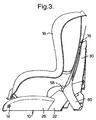
- Figure 3 is a partially broken-away side view of the seat shown in Figure 1, but with the strap deflecting means in its second position;
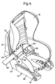
- Figure 4 is a partially broken-away perspective view of the seat as shown in Figure 3;
- Figure 5 is a side view, similar to Figure 3, but showing the seat body in a reclined position; and
- Figure 6 is a schematic side view of another seat in accordance with the invention.
- Referring to Figures 1 and 2, a child safety seat comprises a
base member 10 and aseat assembly 12 which is coupled to thebase member 10 by apivot axle 14. Theseat assembly 12 comprises anintermediate member 16, through which theaxle 14 extends, and aseat body 18. - The
base member 10 consists of a centralhorizontal portion 20 extending below theintermediate member 16 and two L-shaped side portions central portion 20, with theintermediate member 16 located therebetween. Thepivot axle 14 is journalled in forwardly extendinglimbs side portions limbs - The
intermediate member 16 is similar to the base member in that it has abase portion 36 extending under theseat body 18 and L-shaped side portions seat body 18 and the L-shaped side portions base member 10. Theseat body 18 is mounted on theintermediate member 16 in the manner described in EP-A-0822115, which allows the orientation of theseat body 18 to be changed relative to that of theintermediate member 16. - The
base portion 36 of the intermediate member contains an open-ended slot 42 extending longitudinally under theseat body 18. Atransverse rod 44 is slidable along theslot 42 and has its ends connected torespective levers levers stub axles limbs base member 10. Each of thelevers respective side limb pivot pins corresponding lever lap portion 58 of a vehicle seat belt which also has ashoulder portion strap 60. - In use, the child seat is positioned on a vehicle seat so that the
central portion 20 of thebase member 10 rests on the seat cushion and the upwardly extendinglimbs seat body 18 and theintermediate member 16 are pivoted about thepivot axle 14 to the position shown in Figure 1. The V-shaped slots between theside limbs levers guide surfaces base member 10. - Next, the
lap portion 58 of the seat belt for the vehicle seat is threaded overguide surfaces base member 10 and below theside limbs levers lap portion 58 pulled through to theshoulder portion 60. A locking device (not shown), which may be as described in EP-A-0200411, prevents any of the belt from being pulled back to thelap portion 58. - The next step is to pivot the
seat body 18 and theintermediate member 16 rearwardly to the position shown in Figures 3 and 4. Therod 44 slides forwardly along theslot 42, pivoting thelevers side limbs lap portion 58 downwardly from the direct path between the twoguide surfaces base member 10, thereby tightening thevehicle seat belt - Figure 5 shows the
seat body 18 in its reclined position on theintermediate member 16. - Figure 6 shows another child seat which is similar to the seat shown in Figures 1 to 5 in that it has a
base member 70 and aseat assembly 72 which is coupled to thebase member 10 by apivot axle 74. - The
base member 70 is similar to thebase member 10 of Figures 1 to 5 in that it consists of a centralhorizontal portion 76 extending below theseat assembly 72 and two L-shaped side portions 78, extending upwardly from opposite sides of thecentral portion 20 and between which thepivot axle 74 is journalled. Eachside portion 76 also has an upwardly extendinglimb 78 similar to thelimbs - A pair of
levers 80 are mounted on atransverse shaft 82 which is journaled in the rear ends of theside portions 78. Theshaft 82 carries agear wheel 84 which engages with atoothed rack 85 on the bottom edge of aslider 86. Theslider 86 has a secondtoothed rack 88 on its upper edge which is engaged by asecond gear wheel 90 on theshaft 74. With this arrangement, counter-clockwise movement of theseat assembly 72 about theshaft 74 cause clockwise movement of thelevers 80 about theshaft 82. A spring-loadedstrut 94 holds theseat assembly 72 in its raised position as illustrated. - The
base member 70 is held in place by thelap portion 58 of a vehicle seat belt (shown in chain-dotted lines) which extends overguide surfaces 62 on the upper edges of the L-shaped side portions 78. Whenseat assembly 72 is pressed downwards against the action of thestrut 94, thelevers 80 move clockwise from the position illustrated, displacing thelap portion 58 down between theside portions 78 and thereby tightening the vehicle seat belt. Theseat assembly 72 is held in its downwardly displaced position by engagement of a catch (not shown) on the upper ends of the L-shapedside portions 78 with ahook formation 96 on the back of theseat assembly 72. - The
seat assembly 78 may include an intermediate member and a seat body which is mounted on the intermediate member for movement between an upright position and a reclined position, as described with reference to Figures 1 to 5.
Claims (7)
- A child safety seat for use in a vehicle, comprising a base member (10, 70) adapted to rest on a vehicle seat, a seat assembly (12, 72) pivotally mounted on the base member (10, 70) for angular movement about a seat pivot axle (14, 74), guide means (62, 64) on the child seat defining a strap path for a strap (58) of a vehicle seat belt to secure the seat to a vehicle seat and strap deflecting means (54, 56, 80) positioned so that angular movement of the seat assembly (12, 72) relative to the base member (10, 70) causes movement of the strap deflecting means (54, 56, 80) between a first position clear of said strap path and a second position in which a strap (58) following said strap path is deflected therefrom, thereby tightening said strap (58), characterised in that the strap deflecting means comprises a strap-deflecting lever (54, 56, 80) pivotally mounted on the base member (10, 70) for angular movement about a lever pivot axle (50, 52, 82), and a drive assembly (44, 86) coupling the strap-deflecting lever (54, 56, 80) to the seat assembly (12, 72) so that angular movement of the seat assembly (12, 72) towards a position of normal use causes angular movement of the strap-deflecting lever (54, 56, 80) to deflect the strap (58) from said strap path.
- A child safety seat according to claim 1, wherein the drive assembly comprises a second lever (46, 48) fast with the strap-deflecting lever (54, 56) and a cam (42) on the seat assembly (12) engaging with a cam follower (44) on the second lever (46, 48).
- A child safety seat according to claim 2, wherein the cam follower (44) is located on coupled to the second lever (46, 48) at a distance from the lever pivot axle (50, 52, 82) greater than the distance of the strap path from the lever pivot axle (50, 52, 82).
- A child safety seat according to claim 3, wherein the cam comprises a slot (42) in a base portion (36) of the seat assembly (12).
- A child safety seat according to claim 1, wherein the drive assembly comprises a coupler (86) connecting the seat pivot axle (74) to the lever pivot axle (82) so that angular movement of the seat pivot axle (74) in a first direction causes angular movement of the lever pivot axle (82) in a second direction opposite to said first direction.
- A child safety seat according to claim 6 wherein the drive assembly comprises a toothed rack (86) engaging with a first pinion (84) on the on the lever pivot axle (82) and with a second pinion (90) on the seat pivot axle (74).
- A child safety seat according to any preceding claim, wherein the seat assembly includes an intermediate member (16) which is mounted on the base member (10, 70) and coupled by the drive assembly (44, 86) to the strap-deflecting lever (54, 56, 80), together with a seat body (72) which is mounted on the intermediate member (16) for movement between an upright position and a reclined position.
Applications Claiming Priority (2)
| Application Number | Priority Date | Filing Date | Title |
|---|---|---|---|
| GB9919322 | 1999-08-17 | ||
| GBGB9919322.9A GB9919322D0 (en) | 1999-08-17 | 1999-08-17 | Child safety seat |
Publications (3)
| Publication Number | Publication Date |
|---|---|
| EP1077152A2 EP1077152A2 (en) | 2001-02-21 |
| EP1077152A3 EP1077152A3 (en) | 2003-05-07 |
| EP1077152B1 true EP1077152B1 (en) | 2006-03-22 |
Family
ID=10859217
Family Applications (1)
| Application Number | Title | Priority Date | Filing Date |
|---|---|---|---|
| EP00306550A Expired - Lifetime EP1077152B1 (en) | 1999-08-17 | 2000-08-01 | Child safety seat |
Country Status (7)
| Country | Link |
|---|---|
| EP (1) | EP1077152B1 (en) |
| JP (1) | JP4070944B2 (en) |
| AT (1) | ATE320938T1 (en) |
| AU (1) | AU5337700A (en) |
| DE (1) | DE60026793T2 (en) |
| ES (1) | ES2257997T3 (en) |
| GB (1) | GB9919322D0 (en) |
Families Citing this family (17)
| Publication number | Priority date | Publication date | Assignee | Title |
|---|---|---|---|---|
| GB0103983D0 (en) | 2001-02-17 | 2001-04-04 | Britax Roemer Kindersicherheit Gmbh | Child safety seat |
| DK1344678T3 (en) * | 2002-03-15 | 2005-02-28 | Keiper Recaro Gmbh Co | Child safety seat for mounting and attaching to a car seat |
| NL1020767C2 (en) | 2002-06-05 | 2003-12-08 | Maxi Miliaan Bv | High chair. |
| NO20023255A (en) * | 2002-07-04 | 2003-12-08 | Torgersen Hans & Soenn | Seat belt tensioning device |
| DE20213665U1 (en) * | 2002-09-02 | 2002-11-14 | Kiddy Gmbh Autokindersitze | Child safety seat for use in a motor vehicle |
| CN100509476C (en) | 2002-10-11 | 2009-07-08 | 高田株式会社 | Child seats |
| JP4234511B2 (en) * | 2003-06-30 | 2009-03-04 | コンビ株式会社 | child seat |
| ES2259854B1 (en) * | 2003-07-04 | 2007-10-01 | Play, S.A. | SUPPORT SYSTEM FOR A CHILD CHAIR TO THE SEAT OF A CAR. |
| GB0322049D0 (en) * | 2003-09-20 | 2003-10-22 | Britax Roemer Kindersicherheit Gmbh | Child safety seat |
| DE102004005624A1 (en) | 2004-02-04 | 2005-08-25 | Recaro Gmbh & Co. Kg | Child car seat |
| US7216932B2 (en) | 2004-11-04 | 2007-05-15 | Britax Romer Kindersicherheit Gmbh | Half fold belt tensioner |
| US8256840B2 (en) | 2010-06-10 | 2012-09-04 | Britax Child Safety, Inc. | Apparatus and method for attaching a child safety seat to a vehicle seat |
| US8845022B2 (en) * | 2012-09-04 | 2014-09-30 | Britax Child Safety, Inc. | Child seat with belt tensioning mechanism for improved installation |
| US9499074B2 (en) * | 2013-10-25 | 2016-11-22 | Britax Child Safety, Inc. | Forward and rearward facing child seat with belt tensioning mechanism for improved installation |
| US10363842B2 (en) * | 2015-09-11 | 2019-07-30 | Dorel Juvenile Group, Inc. | Vehicle anchor system for juvenile seat base |
| US10322651B2 (en) * | 2016-06-14 | 2019-06-18 | Wonderland Switzerland Ag | Child safety seat |
| US10406947B2 (en) | 2016-08-25 | 2019-09-10 | Dorel Juvenille Group, Inc. | Child restraint for vehicle |
Family Cites Families (4)
| Publication number | Priority date | Publication date | Assignee | Title |
|---|---|---|---|---|
| GB8511066D0 (en) | 1985-05-01 | 1985-06-12 | Britax Excelsior | Child's safety seat |
| EP0306550B1 (en) | 1987-09-10 | 1991-01-23 | Nordischer Maschinenbau Rud. Baader Gmbh + Co Kg | Device for skinning double fish fillets |
| EP0822115B2 (en) * | 1996-08-02 | 2006-05-17 | BRITAX RÖMER Kindersicherheit GmbH | Child safety seat |
| DE19722096A1 (en) * | 1997-05-27 | 1998-12-03 | Baumeister & Ostler Gmbh Co | Child's seat for motor vehicle with at least one holder unit arranged on the child's seat |
-
1999
- 1999-08-17 GB GBGB9919322.9A patent/GB9919322D0/en not_active Ceased
-
2000
- 2000-08-01 DE DE60026793T patent/DE60026793T2/en not_active Expired - Lifetime
- 2000-08-01 ES ES00306550T patent/ES2257997T3/en not_active Expired - Lifetime
- 2000-08-01 AT AT00306550T patent/ATE320938T1/en not_active IP Right Cessation
- 2000-08-01 EP EP00306550A patent/EP1077152B1/en not_active Expired - Lifetime
- 2000-08-14 AU AU53377/00A patent/AU5337700A/en not_active Abandoned
- 2000-08-16 JP JP2000246711A patent/JP4070944B2/en not_active Expired - Lifetime
Also Published As
| Publication number | Publication date |
|---|---|
| JP4070944B2 (en) | 2008-04-02 |
| EP1077152A2 (en) | 2001-02-21 |
| DE60026793D1 (en) | 2006-05-11 |
| DE60026793T2 (en) | 2006-09-14 |
| GB9919322D0 (en) | 1999-10-20 |
| AU5337700A (en) | 2001-02-22 |
| ES2257997T3 (en) | 2006-08-16 |
| EP1077152A3 (en) | 2003-05-07 |
| ATE320938T1 (en) | 2006-04-15 |
| JP2001114003A (en) | 2001-04-24 |
Similar Documents
| Publication | Publication Date | Title |
|---|---|---|
| EP1077152B1 (en) | Child safety seat | |
| EP0619202B1 (en) | Child safety seat for vehicles | |
| US4500133A (en) | Baby chair | |
| US4674797A (en) | Angular position adjustable headrest | |
| EP0732235B1 (en) | Child safety seat | |
| US7017921B2 (en) | Stroller with retaining mechanism | |
| US4186962A (en) | Car seat support and restraining stand | |
| US5577805A (en) | Van-type vehicle seat | |
| EP0447097B1 (en) | Child safety seat | |
| US7040704B2 (en) | Foldable seat system comprising seat belt buckles | |
| EP0371524A1 (en) | Baby seat | |
| US6152525A (en) | Child safety seat | |
| EP0646491A1 (en) | Child safety seat for vehicles | |
| EP1006017A2 (en) | Child safety seat | |
| US7216932B2 (en) | Half fold belt tensioner | |
| EP0485121A1 (en) | Child safety seat | |
| EP1757484A3 (en) | Child car seat | |
| EP1623892B1 (en) | Child vehicle seat | |
| EP0331299A2 (en) | Child's safety seat | |
| EP2233348B1 (en) | Child car seat with lateral stabilizers | |
| EP1232902A2 (en) | Child safety seat | |
| GB2277863A (en) | Child's safety device | |
| FR2772319A1 (en) | Vehicle seat, folds flat to vehicle floor, | |
| US4927210A (en) | Seat with an adjustable fold-down back | |
| GB2247606A (en) | Motor vehicle seat harness including lap straps |
Legal Events
| Date | Code | Title | Description |
|---|---|---|---|
| PUAI | Public reference made under article 153(3) epc to a published international application that has entered the european phase |
Free format text: ORIGINAL CODE: 0009012 |
|
| AK | Designated contracting states |
Kind code of ref document: A2 Designated state(s): AT BE CH CY DE DK ES FI FR GB GR IE IT LI LU MC NL PT SE |
|
| AX | Request for extension of the european patent |
Free format text: AL;LT;LV;MK;RO;SI |
|
| PUAL | Search report despatched |
Free format text: ORIGINAL CODE: 0009013 |
|
| AK | Designated contracting states |
Designated state(s): AT BE CH CY DE DK ES FI FR GB GR IE IT LI LU MC NL PT SE |
|
| AX | Request for extension of the european patent |
Extension state: AL LT LV MK RO SI |
|
| 17P | Request for examination filed |
Effective date: 20030913 |
|
| AKX | Designation fees paid |
Designated state(s): AT BE CH CY DE DK ES FI FR GB GR IE IT LI LU MC NL PT SE |
|
| GRAP | Despatch of communication of intention to grant a patent |
Free format text: ORIGINAL CODE: EPIDOSNIGR1 |
|
| GRAS | Grant fee paid |
Free format text: ORIGINAL CODE: EPIDOSNIGR3 |
|
| GRAA | (expected) grant |
Free format text: ORIGINAL CODE: 0009210 |
|
| AK | Designated contracting states |
Kind code of ref document: B1 Designated state(s): AT BE CH CY DE DK ES FI FR GB GR IE IT LI LU MC NL PT SE |
|
| PG25 | Lapsed in a contracting state [announced via postgrant information from national office to epo] |
Ref country code: LI Free format text: LAPSE BECAUSE OF FAILURE TO SUBMIT A TRANSLATION OF THE DESCRIPTION OR TO PAY THE FEE WITHIN THE PRESCRIBED TIME-LIMIT Effective date: 20060322 Ref country code: CH Free format text: LAPSE BECAUSE OF FAILURE TO SUBMIT A TRANSLATION OF THE DESCRIPTION OR TO PAY THE FEE WITHIN THE PRESCRIBED TIME-LIMIT Effective date: 20060322 Ref country code: AT Free format text: LAPSE BECAUSE OF FAILURE TO SUBMIT A TRANSLATION OF THE DESCRIPTION OR TO PAY THE FEE WITHIN THE PRESCRIBED TIME-LIMIT Effective date: 20060322 Ref country code: BE Free format text: LAPSE BECAUSE OF FAILURE TO SUBMIT A TRANSLATION OF THE DESCRIPTION OR TO PAY THE FEE WITHIN THE PRESCRIBED TIME-LIMIT Effective date: 20060322 |
|
| REG | Reference to a national code |
Ref country code: GB Ref legal event code: FG4D |
|
| REG | Reference to a national code |
Ref country code: CH Ref legal event code: EP |
|
| REG | Reference to a national code |
Ref country code: SE Ref legal event code: TRGR |
|
| REG | Reference to a national code |
Ref country code: IE Ref legal event code: FG4D |
|
| REF | Corresponds to: |
Ref document number: 60026793 Country of ref document: DE Date of ref document: 20060511 Kind code of ref document: P |
|
| PG25 | Lapsed in a contracting state [announced via postgrant information from national office to epo] |
Ref country code: DK Free format text: LAPSE BECAUSE OF FAILURE TO SUBMIT A TRANSLATION OF THE DESCRIPTION OR TO PAY THE FEE WITHIN THE PRESCRIBED TIME-LIMIT Effective date: 20060622 |
|
| PG25 | Lapsed in a contracting state [announced via postgrant information from national office to epo] |
Ref country code: IE Free format text: LAPSE BECAUSE OF NON-PAYMENT OF DUE FEES Effective date: 20060801 |
|
| REG | Reference to a national code |
Ref country code: ES Ref legal event code: FG2A Ref document number: 2257997 Country of ref document: ES Kind code of ref document: T3 |
|
| PG25 | Lapsed in a contracting state [announced via postgrant information from national office to epo] |
Ref country code: PT Free format text: LAPSE BECAUSE OF FAILURE TO SUBMIT A TRANSLATION OF THE DESCRIPTION OR TO PAY THE FEE WITHIN THE PRESCRIBED TIME-LIMIT Effective date: 20060822 |
|
| PG25 | Lapsed in a contracting state [announced via postgrant information from national office to epo] |
Ref country code: MC Free format text: LAPSE BECAUSE OF NON-PAYMENT OF DUE FEES Effective date: 20060831 |
|
| ET | Fr: translation filed | ||
| REG | Reference to a national code |
Ref country code: CH Ref legal event code: PL |
|
| PLBE | No opposition filed within time limit |
Free format text: ORIGINAL CODE: 0009261 |
|
| STAA | Information on the status of an ep patent application or granted ep patent |
Free format text: STATUS: NO OPPOSITION FILED WITHIN TIME LIMIT |
|
| 26N | No opposition filed |
Effective date: 20061227 |
|
| PGFP | Annual fee paid to national office [announced via postgrant information from national office to epo] |
Ref country code: IT Payment date: 20070830 Year of fee payment: 8 Ref country code: SE Payment date: 20070827 Year of fee payment: 8 |
|
| PG25 | Lapsed in a contracting state [announced via postgrant information from national office to epo] |
Ref country code: GR Free format text: LAPSE BECAUSE OF FAILURE TO SUBMIT A TRANSLATION OF THE DESCRIPTION OR TO PAY THE FEE WITHIN THE PRESCRIBED TIME-LIMIT Effective date: 20060623 |
|
| PG25 | Lapsed in a contracting state [announced via postgrant information from national office to epo] |
Ref country code: FI Free format text: LAPSE BECAUSE OF FAILURE TO SUBMIT A TRANSLATION OF THE DESCRIPTION OR TO PAY THE FEE WITHIN THE PRESCRIBED TIME-LIMIT Effective date: 20060322 |
|
| PG25 | Lapsed in a contracting state [announced via postgrant information from national office to epo] |
Ref country code: LU Free format text: LAPSE BECAUSE OF NON-PAYMENT OF DUE FEES Effective date: 20060801 |
|
| PGFP | Annual fee paid to national office [announced via postgrant information from national office to epo] |
Ref country code: ES Payment date: 20080721 Year of fee payment: 9 Ref country code: NL Payment date: 20080828 Year of fee payment: 9 |
|
| PG25 | Lapsed in a contracting state [announced via postgrant information from national office to epo] |
Ref country code: CY Free format text: LAPSE BECAUSE OF FAILURE TO SUBMIT A TRANSLATION OF THE DESCRIPTION OR TO PAY THE FEE WITHIN THE PRESCRIBED TIME-LIMIT Effective date: 20060322 |
|
| EUG | Se: european patent has lapsed | ||
| PG25 | Lapsed in a contracting state [announced via postgrant information from national office to epo] |
Ref country code: IT Free format text: LAPSE BECAUSE OF NON-PAYMENT OF DUE FEES Effective date: 20080801 |
|
| REG | Reference to a national code |
Ref country code: NL Ref legal event code: V1 Effective date: 20100301 |
|
| PG25 | Lapsed in a contracting state [announced via postgrant information from national office to epo] |
Ref country code: NL Free format text: LAPSE BECAUSE OF NON-PAYMENT OF DUE FEES Effective date: 20100301 Ref country code: SE Free format text: LAPSE BECAUSE OF NON-PAYMENT OF DUE FEES Effective date: 20080802 |
|
| REG | Reference to a national code |
Ref country code: ES Ref legal event code: FD2A Effective date: 20090803 |
|
| PG25 | Lapsed in a contracting state [announced via postgrant information from national office to epo] |
Ref country code: ES Free format text: LAPSE BECAUSE OF NON-PAYMENT OF DUE FEES Effective date: 20090802 |
|
| REG | Reference to a national code |
Ref country code: FR Ref legal event code: PLFP Year of fee payment: 17 |
|
| REG | Reference to a national code |
Ref country code: FR Ref legal event code: PLFP Year of fee payment: 18 |
|
| REG | Reference to a national code |
Ref country code: FR Ref legal event code: PLFP Year of fee payment: 19 |
|
| PGFP | Annual fee paid to national office [announced via postgrant information from national office to epo] |
Ref country code: DE Payment date: 20190619 Year of fee payment: 20 Ref country code: FR Payment date: 20190822 Year of fee payment: 20 |
|
| PGFP | Annual fee paid to national office [announced via postgrant information from national office to epo] |
Ref country code: GB Payment date: 20190827 Year of fee payment: 20 |
|
| REG | Reference to a national code |
Ref country code: DE Ref legal event code: R071 Ref document number: 60026793 Country of ref document: DE |
|
| REG | Reference to a national code |
Ref country code: GB Ref legal event code: PE20 Expiry date: 20200731 |
|
| PG25 | Lapsed in a contracting state [announced via postgrant information from national office to epo] |
Ref country code: GB Free format text: LAPSE BECAUSE OF EXPIRATION OF PROTECTION Effective date: 20200731 |