EP1076987B1 - Verfahren und vorrichtung zur überprüfung von sendeleistungspegeln in übertragungssystemen mit begrenzten signalpunkten - Google Patents
Verfahren und vorrichtung zur überprüfung von sendeleistungspegeln in übertragungssystemen mit begrenzten signalpunkten Download PDFInfo
- Publication number
- EP1076987B1 EP1076987B1 EP99912928A EP99912928A EP1076987B1 EP 1076987 B1 EP1076987 B1 EP 1076987B1 EP 99912928 A EP99912928 A EP 99912928A EP 99912928 A EP99912928 A EP 99912928A EP 1076987 B1 EP1076987 B1 EP 1076987B1
- Authority
- EP
- European Patent Office
- Prior art keywords
- transmit power
- modem device
- signal point
- modem
- training
- Prior art date
- Legal status (The legal status is an assumption and is not a legal conclusion. Google has not performed a legal analysis and makes no representation as to the accuracy of the status listed.)
- Expired - Lifetime
Links
- 238000000034 method Methods 0.000 title claims description 71
- 230000005540 biological transmission Effects 0.000 title claims description 32
- 238000012549 training Methods 0.000 claims description 104
- 238000004891 communication Methods 0.000 claims description 60
- 230000001105 regulatory effect Effects 0.000 claims description 10
- 230000004044 response Effects 0.000 claims description 10
- 230000006735 deficit Effects 0.000 claims description 7
- 230000000977 initiatory effect Effects 0.000 claims 2
- 238000012795 verification Methods 0.000 description 26
- 230000008569 process Effects 0.000 description 18
- 238000012545 processing Methods 0.000 description 10
- 238000013461 design Methods 0.000 description 9
- 238000010586 diagram Methods 0.000 description 8
- 230000003044 adaptive effect Effects 0.000 description 6
- 230000008901 benefit Effects 0.000 description 6
- 230000011664 signaling Effects 0.000 description 5
- 238000005516 engineering process Methods 0.000 description 3
- 230000003750 conditioning effect Effects 0.000 description 2
- 238000007796 conventional method Methods 0.000 description 2
- 230000000694 effects Effects 0.000 description 2
- 230000006870 function Effects 0.000 description 2
- 238000012986 modification Methods 0.000 description 2
- 230000004048 modification Effects 0.000 description 2
- 108010076504 Protein Sorting Signals Proteins 0.000 description 1
- 230000002411 adverse Effects 0.000 description 1
- 230000008859 change Effects 0.000 description 1
- 238000006243 chemical reaction Methods 0.000 description 1
- 230000008878 coupling Effects 0.000 description 1
- 238000010168 coupling process Methods 0.000 description 1
- 238000005859 coupling reaction Methods 0.000 description 1
- 238000001514 detection method Methods 0.000 description 1
- 239000000284 extract Substances 0.000 description 1
- 238000009472 formulation Methods 0.000 description 1
- 238000013507 mapping Methods 0.000 description 1
- 239000000203 mixture Substances 0.000 description 1
- 238000005457 optimization Methods 0.000 description 1
- 238000011084 recovery Methods 0.000 description 1
- 238000012163 sequencing technique Methods 0.000 description 1
- 238000007493 shaping process Methods 0.000 description 1
- 230000003595 spectral effect Effects 0.000 description 1
- 230000001360 synchronised effect Effects 0.000 description 1
- 238000012360 testing method Methods 0.000 description 1
Images


Classifications
-
- H—ELECTRICITY
- H04—ELECTRIC COMMUNICATION TECHNIQUE
- H04M—TELEPHONIC COMMUNICATION
- H04M11/00—Telephonic communication systems specially adapted for combination with other electrical systems
- H04M11/06—Simultaneous speech and data transmission, e.g. telegraphic transmission over the same conductors
-
- H—ELECTRICITY
- H04—ELECTRIC COMMUNICATION TECHNIQUE
- H04L—TRANSMISSION OF DIGITAL INFORMATION, e.g. TELEGRAPHIC COMMUNICATION
- H04L25/00—Baseband systems
- H04L25/38—Synchronous or start-stop systems, e.g. for Baudot code
- H04L25/40—Transmitting circuits; Receiving circuits
- H04L25/49—Transmitting circuits; Receiving circuits using code conversion at the transmitter; using predistortion; using insertion of idle bits for obtaining a desired frequency spectrum; using three or more amplitude levels ; Baseband coding techniques specific to data transmission systems
- H04L25/4917—Transmitting circuits; Receiving circuits using code conversion at the transmitter; using predistortion; using insertion of idle bits for obtaining a desired frequency spectrum; using three or more amplitude levels ; Baseband coding techniques specific to data transmission systems using multilevel codes
- H04L25/4927—Transmitting circuits; Receiving circuits using code conversion at the transmitter; using predistortion; using insertion of idle bits for obtaining a desired frequency spectrum; using three or more amplitude levels ; Baseband coding techniques specific to data transmission systems using multilevel codes using levels matched to the quantisation levels of the channel
-
- H—ELECTRICITY
- H04—ELECTRIC COMMUNICATION TECHNIQUE
- H04L—TRANSMISSION OF DIGITAL INFORMATION, e.g. TELEGRAPHIC COMMUNICATION
- H04L5/00—Arrangements affording multiple use of the transmission path
- H04L5/14—Two-way operation using the same type of signal, i.e. duplex
- H04L5/1438—Negotiation of transmission parameters prior to communication
- H04L5/1453—Negotiation of transmission parameters prior to communication of modulation type
Definitions
- the present invention relates generally to the regulation of transmit power levels in a signal point limited data transmission system.
- the present invention relates to a data communication system that verifies whether the total average transmit power of a set of signal point constellations is within a designated transmit power limit.
- FIG. 1 depicts a conceptual diagram of a typical 56 kbps communication path using current PCM modem technology.
- a central site such as an internet service provider (ISP) 100, is digitally connected to a telephone network 130 through a transmitter 110 and a receiver 120 resident at an ISP modem 105.
- the network 130 is connected to a local loop 150 through a central office line card 140.
- the line card typically has a PCM codec implemented therein.
- the local loop 150 is connected to the user's personal computer (PC) 170 at the user's site through the user's modem 160.
- PC personal computer
- the connection between the ISP modem transmitter 110 to the telephone network 130 is a digital connection that supports a typical data rate of about 64 kbps. Since the parameters of the telephone network 130 and line card 140 are dictated and set by the operating specifications of the network, the central site transmitter 110 is configured to transmit the digital data in a particular way to fully exploit its digital connection to the network.
- Transmission power limitations for telecommunication systems may be mandated by regulatory bodies such as the Federal Communications Commission (FCC).
- FCC Federal Communications Commission
- current FCC regulations on modem transmissions over the public telephone network in the United States require that average power levels do not exceed -12 dBm0.
- the particular codewords associated with each transmission session, and the manner in which such codewords are transmitted may be selected to ensure that a specific transmit power level is not exceeded.
- unnecessarily low power levels may cause a low system signal to noise ratio (SNR), which can result in an increased probability of errors and otherwise poor system performance.
- SNR system signal to noise ratio
- modem or other data communication systems that are not limited to the transmission of specific signal points may address the transmit power limitations in a relatively straightforward manner.
- a modem system that is not limited to a particular set of transmit signal points may simply scale its output to comply with any regulatory restrictions.
- signal point limited systems that may utilize signal point constellations designated by a receiver
- no such scaling is possible and the constellation itself dictates the total average transmit power. Accordingly, the constellations designed by the receiver determine whether the transmitter complies with the transmit power regulations.
- the digital modem in a 56 kbps system may initially provide the maximum transmit power limit to the analog modem such that the analog modem can design an appropriate signal point constellation set. Accordingly, after the appropriate signal point constellations are selected, the total average transmit power may be computed by the analog modem to ensure that the transmit power of the constellation set does not exceed the power limit. However, without an independent verification of the transmit power associated with the signal point constellations, the digital modem may utilize a signal point constellation set that, due to computational errors on the part of the analog modem, exceeds the maximum power limit.
- conventional 56 kbps modem systems perform constellation design and power calculation at the analog modem (i.e., the client-end modem) after obtaining a maximum transmit power limit from the digital modem (i.e., the server-end modem).
- the manner in which the analog and digital modems calculate the total average transmit power may vary from one device to the next. In other words, the same transmit power formula may not be rigidly followed by all modem devices. Consequently, the analog and digital modems may generate inconsistent transmit power calculations for the same signal point constellations.
- the analog and digital modems may obtain different transmit power results for the same signal point constellation set.
- the calculation of different results utilizing the same transmit power formula may adversely affect any verification routine performed by the digital modem.
- the digital modem may reject signal point constellations for exceeding the transmit power limit even though the analog modem designed the constellations to be within the power limit and even though the analog modem may have already performed an initial verification.
- Present 56 kbps modem systems may not consider transmission power levels during training procedures. For example, training sequences may be designated in advance without regard to any transmit power limitations imposed on the digital modem. Furthermore, present systems may not effectively select the training signal points in accordance with current operating conditions such as the presence of robbed bit signaling or digital pads. Such digital impairments may have a negative affect on the quality of the training procedure, especially if the training signal points are influenced by the digital impairments.
- Another advantage of the present invention is that it provides a transmit power verification procedure that enables one modem device to verify the transmit power computation of another modem device.
- Another advantage is that the total average transmit power of a signal point constellation set is calculated by both modem devices using the same power formula.
- a further advantage of the present invention is that it provides a transmit power verification scheme that accurately verifies the transmit power of a signal point constellation set regardless of the computational resolution of the components used in the two modem devices.
- Another advantage is that the data communication system is capable of designating a transmit power level for a signal point training sequence used during a training mode.
- the above and other advantages may be carried out in one form by a data communication system for performing signal point limited transmissions.
- the data communication system includes a first modem device and a second modem device configured to communicate with one another over a communication channel, means for selecting a signal point constellation having a first computed transmit power less than or equal to a transmit power limit, and means for verifying that the transmit power of the signal point constellation is less than or equal to the transmit power limit, where the first modem device includes the means for verifying.
- the first computed transmit power is calculated by the second modem device in accordance with a predetermined power calculation formula.
- the data communication system includes means for sending a transmit power limit from the first modem device to the second modem device, and means for selecting a training signal point amplitude having an average transmit power less than or equal to a transmit power limit, where the second device includes the means for selecting.
- the present invention may be described herein in terms of functional block components and various processing steps. It should be appreciated that such functional blocks may be realized by any number of hardware components configured to perform the specified functions. For example, the present invention may employ various integrated circuit components, e.g., memory elements, digital signal processing elements, look-up tables, and the like, which may carry out a variety of functions under the control of one or more microprocessors or other control devices.
- the present invention may be practiced in any number of data communication contexts and that the modem system described herein is merely one exemplary application for the invention. Further, it should be noted that the present invention may employ any number of conventional techniques for data transmission, control signaling, signal processing and conditioning, and the like. Such general techniques are known to those skilled in the art and will not be described in detail herein.
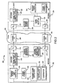
- FIG. 1 An exemplary PCM modem system 100 that may incorporate the principles of the present invention is generally shown in FIG. 1, and FIG. 2 is a more detailed block diagram depiction of a PCM modem system 200 configured in accordance with the present invention.
- FIG. 2 is merely exemplary and is not intended to limit the scope of the present invention in any way. Indeed, for the sake of brevity, conventional timing recovery, automatic gain control (AGC), synchronization, training, and other functional aspects of modem system 200 are not described in detail herein.
- AGC automatic gain control
- the connecting lines shown in FIG. 2 are intended to represent exemplary functional relationships and/or physical couplings between the various elements. Those skilled in the art will recognize that many alternative or additional functional relationships or physical connections may be present in a practical modem system.
- Modem system 200 is preferably configured as a signal point limited transmission system.
- modem system 200 may be limited to the transmission of specific, predetermined signal points contained in a signal point constellation. Indeed, according to current standard operating protocols, all 56 kbps modem systems operate as signal point limited systems.
- modem system 200 includes a first modem, e.g., modem 202, and a second modem, e.g., modem 204.
- Modems 202, 204 are generally configured in accordance with known principles to communicate over the public switched telephone network (PSTN) 205 via at least one communication channel, e.g., channels 206, 208.
- PSTN public switched telephone network
- channel 206 may be considered to be a digital channel and channel 208 may be considered to be an analog or partially analog channel.
- each of modems 202, 204 may include a suitable processor configured to carry out various tasks associated with the operation of modem system 200.
- modem system 200 may incorporate any number of processors or control elements as necessary to support its operation. Such processors or control elements may suitably interact with other functional components of modems 202, 204 to thereby access and manipulate data or monitor and regulate the operation of modem system 200.
- First modem 202 preferably includes an encoder 210 configured to encode digital data in accordance with the particular encoding protocol employed by modem system 200. For example, multiple modulus conversion mapping and -law or A-law signal point assignments may be used in conventional modem systems in accordance with various known and proprietary techniques.
- the output signal generated by encoder 210 may include information for transmission during a data mode, synchronization or training signals for transmission during an initialization mode, or control or other signaling data employed by modem system 200.
- a signal point constellation database 212 (containing the particular signal points utilized for the current communication session) may be associated with encoder 210, as depicted in FIG. 2. It should be appreciated that database 212 need not be an integral part of encoder 210 and that modem 202 may implement database 212 in a different manner than that shown.
- Modem 202 includes a transmitter 214, which is configured to transmit encoded symbols in accordance with general PCM techniques. Such symbols may include data, training signals, synchronization signals, control signals, and the like. Modem 202 also includes a receiver 215, which is preferably configured in accordance with conventional modem technologies. Receiver 215 is configured to receive data from modem 204; such data may include encoded information bits, control signals, functional parameters or identifiers, and any other data employed by conventional modem systems. For example, and as described in more detail below, modem 204 may be configured to send information indicative of optimized signal point constellations to modem 202 for use during transmission of subsequent signal segments. Of course, modem 202 may employ any suitable alternative device or technique for receiving the optimized signal point constellations from modem 204. A decoder (not shown) resident at modem 202 may be used to decode any signals transmitted from modem 204 to modem 202, including the signal that conveys the signal point constellations.
- modem 202 is also configured to send modem 204, via transmitter 214, a transmit power limit that may govern one or more training signal points or one or more signal point constellations.
- the transmit power limit may be associated with a regulatory limit imposed upon modem 202, e.g., the -12 dBm0 FCC limit.
- modem 202 may suitably generate the transmit power limit to compensate for a computational tolerance of modem 202 (and/or modem 204), operational characteristics of the communication channels, or the like, to ensure that the power verification techniques of the present invention are carried out in an effective and robust manner.
- the transmit power limit may be calculated by a transmit power limit generator 216, which preferably uses a designated transmit power formula 218 known by both modems 202, 204.
- the use of the designated power formula 218 may be desirable to ensure that modems 202, 204 perform compatible power calculations that can be compared in a meaningful manner.
- modem 202 is suitably configured to select power formula 218 from a plurality of formulas.
- modem system 200 is capable of selecting a power formula expression to contemplate the use of line coding, spectral shaping, or other current operating characteristics or functional features of the telephone network or modem system 200.
- modem 202 may suitably communicate the selected transmit power formula to modem 204 during an initialization or startup procedure. It should be appreciated that the power formula selection may instead be carried out by modem 204.
- the transmit power limit may be utilized by modem system 200 as a design parameter during the selection and verification of signal point constellations and/or training signal points having particular amplitudes. Consequently, the transmit power formula 218 may also be utilized by a transmit power verification element 220. Transmit power verification element 220 is configured to verify that the total average transmit power of the signal point constellations designed by modem 204 is less than or equal to the relevant transmit power limit. This verification feature enables modem 202 to verify the transmit power associated with the constellations rather than merely assuming that the constellations are within the transmit power limit. Furthermore, because both modems 202, 204 utilize the same formula for calculating the transmit power, the likelihood of an erroneous verification is reduced.
- transmit power verification element 220 may be configured to accept or reject signal point constellations on the basis of any suitable threshold or comparison relative to the transmit power limit, and that the conditions for verification described herein are merely exemplary.
- Transmit power verification element 220 may include or be operatively associated with a transmit power calculation element 222 and a comparator element 224.
- Power calculation element 222 is preferably configured to calculate, in accordance with the predetermined power calculation formula 218, a computed transmit power of the signal point constellations designed by modem 204.
- transmit power considerations can play an important role during adaptive signal point constellation design and various optimization techniques. Accordingly, modem systems must be designed to operate in a robust and reliable manner while maintaining the total average transmit power within the given limit. For this reason, if the transmit power of a constellation exceeds the power limit, then the modem system 200 may redesign the constellation such that its total average power is within an acceptable range.
- the preferred 56 kbps modem embodiment employs a power formula 218 that contemplates the unequal probability of occurrences associated with the signal points within the signal point constellations.
- the power calculation initially determines the probability of transmission of each individual signal point within a particular constellation. Then, the probabilities of occurrence are used to generate the average total power for each constellation (current 56 kbps modem systems use six signal point constellations associated with different data frame segments). Finally, the power for all of the constellations is determined and averaged to produce the total average power for the given data communication session.
- An exemplary exact power calculation scheme suitable for use with modem system 200 is described in detail in United States Patent NO. 6,034,991, issued March 7, 2000.
- Comparator element 224 is suitably configured to determine whether the total average transmit power calculated by power calculation element 222 is less than or equal to the transmit power limit. Accordingly, transmit power verification element 220 may receive the transmit power limit from, or otherwise operate in conjunction with, transmit power limit generator 216. Power verification element 220 is preferably configured to accept or reject the signal point constellations provided by modem 204 in response to the determination made by comparator 224 (described in more detail below).
- modem 202 may include a control and processing element 226 associated with the generation of training sequences that contain the training point amplitudes selected by modem 204.
- Control and processing element 226 is preferably configured to control the operation of a training sequence generator 228.
- training sequence generator 228 may format the training sequence such that it includes a plurality of signal points corresponding to positive and negative values of the particular training point amplitude.
- training sequence generator may include a suitable polarity assigner (not shown) that assigns a positive or a negative polarity to the transmitted training symbols.
- receiver 230 signals transmitted to modem 204 over channel 206 are received by a receiver 230.
- receiver 230 may include any number of additional components (that may be known in the art) for decoding, equalization, conditioning, or other processing of the received signal.
- Modem 204 processes received data signals to obtain the original digital data encoded by modem 202;
- modem 204 includes a decoder 232 to suitably decode the received symbols in accordance with the same encoding scheme employed by encoder 210.
- decoder 232 may have a signal point constellation database 234 associated therewith. Database 234 is preferably utilized to store the same signal point constellations that are stored at and utilized by modem 202 for the current communication session.
- Modem 204 may include a receiver training control block 236 that initiates and regulates training or resynchronization processes within modem 204. As shown in FIG. 2, receiver training control block 236 may be associated with receiver 230 to enable the adaptive equalization of receiver 230 in response to the training sequence sent by modem 202. As described above, prior to the training procedure, modem 204 may receive a predetermined transmit power limit from modem 202. Modem 204 may then access a signal point selector 238 to determine which training signal point amplitude would be suitable for the given power limit. For complex training sequences that include more than one signal point, modem 204 may utilize a transmit power calculation element 242 (that uses a designated transmit power formula 240) to suitably calculate the transmit power associated with the training signal points or the proposed training sequence itself.
- a transmit power calculation element 242 that uses a designated transmit power formula 240
- Signal point selector 238 is also configured to select at least one signal point constellation (and preferably a set of constellations) such that the signal point constellation set has a computed transmit power less than or equal to the transmit power limit identified by modem 202.
- Power calculation element 242 computes the total average power of the signal point constellations in accordance with the designated power formula 240 and in a similar manner as transmit power calculation element 222 (resident at modem 202).
- modem 204 is the first device to compute the total constellation transmit power.
- Modem 202 subsequently verifies that the computed transmit power is indeed within the specified transmit power limit. If the calculation performed by modem 202 determines that a constellation set designed by modem 202 exceeds the transmit power limit, then that constellation set is either discarded or modified by signal point selector 238 until an acceptable constellation set is obtained.
- a transmitter 244 is preferably utilized to send information indicative of the designated training signal point amplitude or amplitudes to modem 202.
- the information transmitted by transmitter 244 is encoded prior to transmission over PSTN 205.
- modem 202 Upon receipt of this information, modem 202 performs decoding and processing to obtain the training point amplitudes for subsequent use by training sequence generator 228. Then, during a training mode, a suitable training sequence is sent from modem 202 to modem 204. Thereafter, the signal point constellations (within the designated transmit power limit) designed by modem 204 are transmitted, via transmitter 244, to modem 202.
- Modem 202 suitably extracts the signal point constellations for the transmit power verification procedure. If modem 202 verifies the signal point constellations, then a data communication session can be initiated.
- Process 300 is illustrated as a flow diagram. Although not depicted as such, specific portions of process 300 may be performed by modem 202 or modem 204. Process 300 is preferably performed by modems 202, 204 during an initialization or startup procedure after communication channels 206, 208 have been established. Process 300 may begin with a task 302, during which modems 202, 204 enter a training mode. Task 302 may be prompted by a certain control signal sequence transmitted by modem 202. Alternatively, task 302 may follow a predetermined sequence of initialization or startup routines, where such sequencing is synchronized at both modems 202, 204.
- a task 304 may be performed to cause modem 202 to generate a transmit power limit for application during the selection of one or more training signal points.
- the transmit power limit may be suitably generated in response to a computational tolerance of modem 202 (and/or modem 204), a regulatory limit imposed upon transmissions by modem 202, or operational characteristics of communication channels 206 or 208. Regulatory limits that rarely change, such as the -12 dBm0 FCC power limit described above, may be stored in a suitable memory element for access by transmit power limit generator 216.
- modem 202 may generate new transmit power limits for each communication session to compensate for other functional parameters.
- modem 202 may generate a lower transmit power limit to compensate for the nonlinearity of network codecs present in channels 206, 208.
- modem 202 may lower the transmit power limit to ensure that its computational precision does not cause an erroneous acceptance or rejection of training points or a signal point constellation set designed by modem 204.
- a task 306 is preferably performed to cause modem 202 to send the current transmit power limit to modem 204.
- modem 204 receives the current transmit power limit during task 306.
- Modem 204 uses the received transmit power limit to select at least one suitable training signal point (task 308).
- signal point selector 238 is preferably configured to perform task 308.
- one training point amplitude is selected during task 308, i.e., the resultant training signal is a sequence of positive and negative symbols containing the specified signal point amplitude.
- Modem 204 selects a training signal point having an average transmit power less than or equal to the transmit power limit.
- modem 204 may consider any number of factors during the selection of the training signal point. Such flexibility may be desirable to enable modem system 200 to contemplate practical limitations associated with the current communication session. For example, the selection of the training signal amplitude may be biased toward those signal points having relatively higher average transmit powers. The use of higher power signal points is desirable to increase the signal to noise ratio associated with the subsequent transmission of the training sequence. This additional consideration may also be associated with the design of the signal point constellations used during the data mode.
- the selection of the training point may also be responsive to the presence of a digital impairment, e.g., robbed bit signaling (RBS), within communication channel 206.
- a digital impairment e.g., robbed bit signaling (RBS)
- the training point may be selected to either reduce the effect of RBS within the received training sequence or to increase the detection of RBS within the received training sequence.
- RBS robbed bit signaling
- the training signal point amplitude (or a corresponding codeword) may be represented by a number of digital bits, and signal point selector 238 may be suitably configured to select the training signal point amplitude in accordance with a predetermined bit assignment for at least one of the digital bits that represent the signal point amplitude.
- task 308 may be designed to select a training signal point amplitude that is represented by a codeword having a "1" as its least significant bit (such a selection would reduce the effect of RBS in the training sequence).
- task 308 may instead select a training signal point amplitude that is represented by a codeword having a "0" as its least significant bit.
- a task 310 is performed.
- the specific training signal point amplitude (or data indicative thereof) is sent from modem 204 to modem 202 in an appropriate manner.
- modem 202 suitably receives the training signal point amplitude during task 310.
- training sequence control and processing element 226 may receive the training signal point amplitude and thereafter control the operation of training sequence generator 228.
- a task 312 is preferably performed to generate a training sequence that includes a plurality of signal points corresponding to the specified amplitude.
- task 312 may suitably assign positive and negative polarities to the plurality of signal points to form the training sequence. The particular polarity assignment may vary for different applications or to accomplish different training objectives.
- a task 314 causes modem 202 to transmit the training sequence over channel 206.
- Modem 204 suitably receives the training sequence during task 314 and thereafter trains receiver 230 (and any other applicable components) in response to the training sequence.
- training point selection process ends.
- modem system 200 may enter an adaptive constellation design mode followed by a data transmission mode.
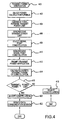
- the adaptive constellation design mode may be performed in conjunction with a transmit power verification process 400, which is illustrated as a flow diagram in FIG. 4. Portions of process 400 may be performed by modem 202 while other portions of process 400 may be performed by modem 204.
- Process 400 may begin with a task 402, which causes modem system 200 to select a transmit power calculation formula from a plurality of formulas. Task 402 may not be necessary in systems that utilize only one predetermined power calculation formula. In other systems, task 402 may be desirable to enable the selection of a transmit power formula that is particularly suitable for communication channels 206, 208 or for the current operating characteristics of modem system 200. If necessary, task 402 may be performed at either of modems 202, 204, and the selected power formula may be communicated between modems 202, 204 via a suitably transmitted control sequence.
- a task 404 may be performed to generate, in accordance with the selected power calculation formula, a transmit power limit.
- task 404 is preferably performed by modem 202 and, in particular, transmit power limit generator 216 (see FIG. 2 ).
- task 404 generates a limit for the total average transmit power for use by modem 204 during the adaptive design of a set of signal point constellations.
- the transmit power limit may be suitably generated in response to a computational tolerance of modem 202 (and/or modem 204), a regulatory limit imposed upon transmissions by modem 202, or operational characteristics of communication channels 206 or 208.
- a task 406 causes modem 202 to send the transmit power limit (generated during task 404) to modem 204; modem 204 receives the transmit power limit during task 406, After modem 204 receives the transmit power limit, a task 408 is preferably performed to select a signal point constellation (or a set of constellations) such that the constellation set has a first computed transmit power less than or equal to the transmit power limit (as described above, the constellation set may be alternatively designed to satisfy any condition relative to the power limit). The first computed transmit power is calculated in accordance with the designated power calculation formula. Thus, both modems 202, 204 utilize a consistent power formula during their respective calculations.
- the first computed transmit power is associated with an upper bound calculation with respect to the predetermined power calculation formula.
- the finite arithmetic precision of modem 204 is taken into consideration such that the first computed transmit power will not be less than a computed value using infinite precision arithmetic.
- modem 204 need not always employ an upper bound calculation. For example, if suitable approximation power formulas are used that are known to provide a result within a certain error margin, then that error margin can be added to the result of the power calculation before it is compared to the transmit power limit.
- the selection of the specific constellation signal points may be governed by a number of criteria other than transmit power, e.g., network and channel characteristics. Consequently, any number of conventional techniques may be employed during task 408; a detailed explanation of such techniques, including adaptive constellation design, is beyond the scope of this description.
- modem 204 has preferably designed a set of signal point constellations that, according to the calculations performed by modem 204, have a total average transmit power less than or equal to the transmit power limit.
- a task 410 causes modem 204 to transmit the constellations (or data indicative of the constellations) to modem 202, which suitably receives the constellations.
- a task 412 may be performed to prompt modem 202 to verify that the total average transmit power of the constellations is less than or equal to the designated transmit power limit.
- Modem system 200 may utilize conventional control or signaling techniques to perform task 412.
- modem 202 verifies the total transmit power by calculating, in accordance with the predetermined power calculation formula, a second computed transmit power of the signal point constellations.
- task 414 is performed such that the second computed transmit power is obtained in accordance with a lower bound calculation with respect to the designated power formula.
- the finite arithmetic precision of modem 202 is taken into consideration such that the first computed transmit power will not be greater than a computed value using infinite precision arithmetic.
- the lower bound calculation is preferably utilized to ensure that modem 202 does not reject constellations that were correctly designed by modem 204. It should be appreciated that modem 202 need not always employ a lower bound calculation. For example, if suitable approximation power formulas are used that are known to provide a result within a certain error margin, then the transmit power limit can be selected at an appropriately lower level to include the certain error margin.
- a query task 416 may be performed by comparator 224 (see FIG. 2 ) to test whether the second computed transmit power is less than or equal to the designated total transmit power limit.
- the specific condition analyzed during query task 416 may vary according to the particular system. If query task 416 determines that the second calculated transmit power exceeds the predetermined power limit, then a task 418 is preferably performed to reject the current set of signal point constellations. Following task 418, transmit power verification process 400 ends. Task 418 may prompt modem 204 to perform a redesign of the constellations to lower the transmit power, i.e., process 400 may be reentered at task 408 following task 418.
- a task 420 is performed to accept the set of constellations designed by modem 204. Acceptance or verification of the signal point constellations may cause the constellations to be suitably stored at, e.g., constellation database 212 for subsequent use during the data mode. Following task 420, a task 422 may prompt modem system 200 to initiate a data communication session utilizing the current (and verified) signal point constellations. Process 400 ends after task 422. Thus, process 400 ensures that modems 202, 204 both utilize the same transmit power formula during their respective calculations, while providing a transmit power verification procedure for modem system 200.
- the present invention provides an improved data communication system for performing signal point limited transmissions.
- a modem system in accordance with the present invention performs a transmit power verification procedure that enables one modem device to verify the transmit power computation of another modem device.
- the transmit power verification scheme accurately verifies the transmit power of a signal point constellation set regardless of the computational resolution of the components used in the two modem devices.
- the total average transmit power of a signal point constellation set is calculated by both modem devices using the same power formula.
- the modem system is capable of designating a transmit power level for a signal point training sequence used during a training mode.
Landscapes
- Engineering & Computer Science (AREA)
- Signal Processing (AREA)
- Computer Networks & Wireless Communication (AREA)
- Quality & Reliability (AREA)
- Physics & Mathematics (AREA)
- Spectroscopy & Molecular Physics (AREA)
- Telephonic Communication Services (AREA)
- Cable Transmission Systems, Equalization Of Radio And Reduction Of Echo (AREA)
- Digital Transmission Methods That Use Modulated Carrier Waves (AREA)
- Bidirectional Digital Transmission (AREA)
- Monitoring And Testing Of Transmission In General (AREA)
Claims (49)
- Verfahren zum Verifizieren von Sendeleistungspegeln in einem signalstellenbegrenzten Übertragungssystem mit einer ersten Modemvorrichtung (202), die zum Kommunizieren mit einer zweiten Modemvorrichtung (204) über einen Kommunikationskanal (206) (208) konfiguriert ist, wobei das Verfahren die folgenden Schritte aufweist:Empfangen (215) einer Vielzahl von Signalstellen bei der ersten Modemvorrichtung (202), wobei die Vielzahl von Signalstellen eine erste berechnete Sendeleistung hat, die kleiner als eine oder gleich einer Sendeleistungsgrenze ist, wobei die erste berechnete Sendeleistung gemäß einer vorbestimmten Leistungsberechnungsformel (218) berechnet wird (242);Berechnen (222) einer zweiten berechneten Sendeleistung der Vielzahl von Signalstellen gemäß der vorbestimmten Leistungsberechnungsformel (218); undBestimmen (224), ob die zweite berechnete Sendeleistung kleiner als die oder gleich der Sendeleistungsgrenze ist, wobei der Bestimmungsschritt durch die erste Modemvorrichtung (202) durchgeführt wird.
- Verfahren nach Anspruch 1, wobei die erste berechnete Sendeleistung kleiner als die Sendeleistungsgrenze ist.
- Verfahren nach Anspruch 1, wobei die zweite berechnete Sendeleistung kleiner als die Sendeleistungsgrenze ist.
- Verfahren nach Anspruch 1, das weiterhin die folgenden Schritte aufweist:Erzeugen (216) der Sendeleistungsgrenze gemäß der vorbestimmten Leistungsberechnungsformel (218), wobei der Berechnungsschritt (222) durch die erste Modemvorrichtung (202) durchgeführt wird, undSenden (214) der Sendeleistungsgrenze von der ersten Modemvorrichtung (202) zur zweiten Modemvorrichtung (204).
- Verfahren nach Anspruch 4, wobei der Erzeugungsschritt (216) eine gesamte durchschnittliche Sendeleistungsgrenze erzeugt.
- Verfahren nach Anspruch 1, das weiterhin die folgenden Schritte aufweist:Annehmen (220) der Vielzahl von Signalstellen, wenn der Bestimmungsschritt (224) bestimmt, dass die zweite berechnete Sendeleistung kleiner als die oder gleich der Sendeleistungsgrenze ist; undZurückweisen (220) der Vielzahl von Signalstellen, wenn der Bestimmungsschritt (224) bestimmt, dass die zweite berechnete Sendeleistung größer als die Sendeleistungsgrenze ist.
- Verfahren nach Anspruch 1, wobei die erste berechnete Sendeleistung zu einer Berechnung mit einer oberen Grenze in Bezug auf die vorbestimmte Leistungsberechnungsformel (218) gehört.
- Verfahren nach Anspruch 1, wobei der Berechnungsschritt (222) die zweite berechnete Sendeleistung gemäß einer Berechnung mit einer unteren Grenze in Bezug auf die vorbestimmte Leistungsberechnungsformel (218) berechnet.
- Verfahren nach Anspruch 1, das weiterhin den Schritt zum Auswählen (216) der vorbestimmten Leistungsberechnungsformel (204) aus einer Vielzahl von Formeln aufweist.
- Verfahren nach Anspruch 9, wobei der Auswahlschritt auf aktuelle Betriebscharakteristiken des Sendesystems reagiert.
- Verfahren nach Anspruch 1, das weiterhin den Schritt zum Erzeugen (216) der Sendeleistungsgrenze gemäß der vorbestimmten Leistungsberechnungsformel (218) und in Reaktion auf wenigstens eines voneiner Berechnungstoleranz der ersten Modemvorrichtung (202);einer Regelungsgrenze, die der ersten Modemvorrichtung (202) auferlegt ist; undBetriebscharakteristiken des Kommunikationskanals (206) (208) aufweist.
- Verfahren zum Verifizieren von Sendeleistungspegeln in einem signalstellenbegrenzten Sendesystem (200) mit einer ersten Modemvorrichtung (202), die zum Kommunizieren mit einer zweiten Modemvorrichtung (204) über einen Kommunikationskanal (206) (208) konfiguriert ist, wobei das Verfahren die folgenden Schritte aufweist:Empfangen (230) einer gemäß einer vorbestimmten Leistungsberechnungsformel (218) berechneten Sendeleistungsgrenze bei der zweiten Modemvorrichtung (204);Auswählen (238) wenigstens einer Signalstellenkonstellation, so dass die wenigstens eine Signalstellenkonstellation eine erste berechnete Sendeleistung hat, die kleiner als die oder gleich der Sendeleistungsgrenze ist, wobei die erste berechnete Sendeleistung gemäß der vorbestimmten Leistungsberechnungsformel (218) berechnet wird;Senden (244) der wenigstens einen Signalstellenkonstellation von der zweiten Modemvorrichtung (244) zur ersten Modemvorrichtung (202); undVeranlassen, dass die erste Modemvorrichtung (202) verifiziert, dass die Sendeleistung der wenigstens einen Signalstellenkonstellation kleiner als die oder gleich der Sendeleistungsgrenze (220) ist.
- Verfahren nach Anspruch 12, das weiterhin die folgenden Schritte aufweist:Berechnen (222) einer zweiten berechneten Sendeleistung der wenigstens einen Signalstellenkonstellation gemäß der vorbestimmten Leistungsberechnungsformel (218); undBestimmen (224), ob die zweite berechnete Sendeleistung kleiner als die oder gleich der Sendeleistungsgrenze ist, wobei der Bestimmungsschritt durch die erste Modemvorrichtung (202) durchgeführt wird.
- Verfahren nach Anspruch 13, das weiterhin den Schritt zum Initiieren einer Datenkommunikationssession (210) unter Verwendung der wenigstens einen Signalstellenkonstellation aufweist.
- Verfahren nach Anspruch 14, wobei der Initiierungsschritt (210) durchgeführt wird, wenn der Bestimmungsschritt (224) bestimmt, dass die zweite berechnete Sendeleistung kleiner als die oder gleich der Sendeleistungsgrenze ist.
- Verfahren nach Anspruch 12, wobei die erste berechnete Sendeleistung zu einer Berechnung mit einer oberen Grenze in Bezug auf die vorbestimmte Leistungsberechnungsformel (218) gehört.
- Verfahren nach Anspruch 12, das weiterhin den Schritt zum Auswählen (216) der vorbestimmten Leistungsberechnungsformel (218) aus einer Vielzahl von Formeln aufweist.
- Verfahren nach Anspruch 17, wobei der Auswahlschritt (216) auf aktuelle Betriebscharakteristiken des Sendesystems reagiert.
- Datenkommunikationssystem (200) zum Durchführen von signalstellenbegrenzten Sendungen, wobei das System folgendes aufweist:eine erste Modemvorrichtung (202) und eine zweite Modemvorrichtung (204), die zum Kommunizieren miteinander über einen Kommunikationskanal (206) (208) konfiguriert sind;eine Einrichtung zum Auswählen (238) wenigstens einer Signalstellenkonstellation bei der zweiten Modemvorrichtung (204), so dass die wenigstens eine Signalstellenkonstellation eine erste berechnete Sendeleistung hat, die kleiner als eine oder gleich einer Sendeleistungsgrenze ist, wobei die erste berechnete Sendeleistung durch die zweite Modemvorrichtung (204) gemäß einer vorbestimmten Leistungsberechnungsformel (218) berechnet wird; undeine Einrichtung zum Verifizieren (220), dass die Sendeleistung der wenigstens einen Signalstellenkonstellation kleiner als die oder gleich der Sendeleistungsgrenze ist, wobei die erste Modemvorrichtung (202) die Einrichtung zum Verifizieren aufweist.
- Datenkommunikationssystem nach Anspruch 19, wobei die Einrichtung zum Auswählen (238) zum Auswählen der wenigstens einen Signalstellenkonstellation so konfiguriert ist, dass die erste berechnete Sendeleistung kleiner als die Sendeleistungsgrenze ist.
- Datenkommunikationssystem nach Anspruch 19, wobei die Einrichtung zum Verifizieren (220) konfiguriert ist, um zu verifizieren, dass die Sendeleistung der wenigstens einen Signalstellenkonstellation kleiner als die Sendeleistungsgrenze ist.
- Datenkommunikationssystem nach Anspruch 19, wobei die erste berechnete Sendeleistung zu einer Berechnung mit einer oberen Grenze in Bezug auf die vorbestimmte Leistungsberechnungsformel (218) gehört.
- Datenkommunikationssystem nach Anspruch 19, wobei die erste Modemvorrichtung (202) weiterhin eine Einrichtung zum Berechnen (222) der Sendeleistungsgrenze gemäß der vorbestimmten Leistungsberechnungsformel (218) aufweist.
- Datenkommunikationssystem nach Anspruch 23, wobei die Einrichtung zum Berechnen (222) zum Berechnen einer gesamten durchschnittlichen Sendeleistungsgrenze konfiguriert ist.
- Datenkommunikationssystem nach Anspruch 19, wobei die erste Modemvorrichtung (202) weiterhin einen ersten Sender (214) aufweist, der zum Senden der Sendeleistungsgrenze zur zweiten Modemvorrichtung (204) konfiguriert ist.
- Datenkommunikationssystem nach Anspruch 19, wobei die zweite Modemvorrichtung (204) weiterhin einen zweiten Sender (244) aufweist, der zum Senden der wenigstens einen Signalstellenkonstellation zur ersten Modemvorrichtung (202) konfiguriert ist.
- Datenkommunikationssystem nach Anspruch 19, wobei die Einrichtung zum Verifizieren (220) folgendes aufweist:eine Einrichtung zum Berechnen (222) einer zweiten berechneten Sendeleistung der wenigstens einen Signalstellenkonstellation gemäß der vorbestimmten Leistungsberechnungsformel (220); undeine Einrichtung zum Bestimmen (224), ob die zweite berechnete Sendeleistung kleiner als die oder gleich der Sendeleistungsgrenze ist.
- Datenkommunikationssystem nach Anspruch 27, wobei die Einrichtung zum Berechnen (222) die zweite berechnete Sendeleistung gemäß einer Berechnung mit einer unteren Grenze in Bezug auf die vorbestimmte Leistungsberechnungsformel (218) berechnet.
- Datenkommunikationssystem nach Anspruch 19, das weiterhin eine Einrichtung zum Auswählen (216) der vorbestimmten Leistungsberechnungsformel aus einer Vielzahl von Formeln aufweist.
- Datenkommunikationssystem nach Anspruch 29, wobei die Einrichtung zum Auswählen (216) zum Auswählen der vorbestimmten Leistungsberechnungsformel (218) gemäß aktuellen Betriebscharakteristiken des Sendesystems (200) konfiguriert ist.
- Datenkommunikationssystem nach Anspruch 19, wobei die erste Modemvorrichtung (202) weiterhin eine Einrichtung zum Erzeugen (216) der Sendeleistungsgrenze gemäß der vorbestimmten Leistungsberechnungsformel (218) und in Reaktion auf wenigstens eines voneiner Berechnungstoleranz der ersten Modemvorrichtung (202);einer Regelungsgrenze, die der ersten Modemvorrichtung (202) auferlegt ist; undBetriebscharakteristiken des Kommunikationskanals (206) (208) aufweist.
- Datenkommunikationssystem (200) zum Durchführen von signalstellenbegrenzten Sendungen, wobei das System folgendes aufweist:eine erste Modemvorrichtung (202) und eine zweite Modemvorrichtung (204), die zum Kommunizieren miteinander über einen Kommunikationskanal (206) (208) konfiguriert sind;eine Einrichtung zum Senden (214) einer Sendeleistungsgrenze von der ersten Modemvorrichtung (202) zur zweiten Modemvorrichtung (204); undeine Einrichtung zum Auswählen (238) wenigstens einer Schulungs-Signalstellenamplitude mit einer gesamten durchschnittlichen Sendeleistung, die kleiner als eine oder gleich einer Sendleistungsgrenze ist, wobei die zweite Modemvorrichtung (204) die Einrichtung zum Auswählen (238) aufweist.
- Datenkommunikationssystem nach Anspruch 32, wobei die erste Modemvorrichtung (202) weiterhin eine Einrichtung zum Erzeugen einer Schulungssequenz (228) mit einer Vielzahl von Signalstellen entsprechend der wenigstens einen Schulungs-Signalstellenamplitude aufweist.
- Datenkommunikationssystem nach Anspruch 33, wobei die Einrichtung zum Erzeugen (228) der Vielzahl von Signalstellen positive und negative Polaritäten zuordnet.
- Datenkommunikationssystem nach Anspruch 32, wobei:eine Schulungs-Signalstellenamplitude durch eine Anzahl von digitalen Bits dargestellt wird; unddie Einrichtung zum Auswählen (238) zum Auswählen der wenigstens einen Schulungs-Signalstellenamplitude gemäß einer vorbestimmten Bit-Zuordnung für wenigstens eines der Anzahl von digitalen Bits konfiguriert ist.
- Datenkommunikationssystem nach Anspruch 32, wobei die Einrichtung zum Auswählen (238) zum Auswählen der wenigstens einen Schulungs-Signallstellenamplitude in Reaktion auf das Vorhandensein einer digitalen Beeinträchtigung innerhalb des Kommunikationskanals (206) (208) konfiguriert ist.
- Datenkommunikationssystem nach Anspruch 32, wobei die Einrichtung zum Auswählen (238) zum Bevorzugen der Auswahl von Schulungs-Signalstellenamplituden mit relativ höheren durchschnittlichen Sendeleistungen konfiguriert ist.
- Datenkommunikationssystem nach Anspruch 32, wobei die Einrichtung zum Auswählen (238) die wenigstens eine Schulungs-Signalstellenamplitude so auswählt, dass die wenigstens eine Schulungs-Signalstellenamplitude eine gesamte durchschnittliche Sendeleistung hat, die kleiner als die Sendeleistungsgrenze ist.
- Verfahren zum Bestimmen von Sendeleistungspegeln, die zu einem Schulungsmode gehören, in einem signalstellenbegrenzten Sendesystem (200) mit einer ersten Modemvorrichtung (202), die zum Kommunizieren mit einer zweiten Modemvorrichtung (204) über einen Kommunikationskanal (206) (208) konfiguriert ist, wobei das Verfahren die folgenden Schritte aufweist:Eintreten in einen Schulungsmode zwischen der ersten Modemvorrichtung (202) und der zweiten Modemvorrichtung (204);Senden (214) einer Sendeleistungsgrenze von der ersten Modemvorrichtung (202) zu der zweiten Modemvorrichtung (204);Empfangen (215) wenigstens einer Schulungs-Signalstellenamplitude bei der ersten Modemvorrichtung (202), wobei die wenigstens eine Schulungs-Signalstellenamplitude eine durchschnittliche Sendeleistung hat, die kleiner als die oder gleich der Sendeleistungsgrenze ist; undErzeugen (228) einer Schulungssequenz mit einer Vielzahl von Signalstellen entsprechend der wenigstens einen Schulungs-Signalstellenamplitude bei der ersten Modemvorrichtung (202).
- Verfahren nach Anspruch 39, wobei der Empfangsschritt (215) eine Schulungs-Signalstellenamplitude empfängt.
- Verfahren nach Anspruch 40, wobei der Erzeugungsschritt (228) der Vielzahl von Signalstellen positive und negative Polaritäten zuordnet.
- Verfahren nach Anspruch 40, wobei:die eine Schulungs-Signalstellenamplitude durch eine Anzahl von digitalen Bits dargestellt wird; unddie Anzahl von digitalen Bits in Reaktion auf das Vorhandensein einer digitalen Beeinträchtigung innerhalb des Kommunikationskanals ausgewählt wird.
- Verfahren nach Anspruch 39, das weiterhin den Schritt zum Erzeugen (216) der Sendeleistungsgrenze in Reaktion auf wenigstens eines von:einer Berechnungstoleranz der ersten Modemvorrichtung (202);einer Regelungsgrenze, die der ersten Modemvorrichtung (202) auferlegt ist; undBetriebscharakteristiken des Kommunikationskanals (206) (208) aufweist.
- Verfahren zum Bestimmen von Sendeleistungspegeln, die zu einem Schulungsmode gehören, in einem signalstellenbegrenzten Sendesystem (200) mit einer ersten Modemvorrichtung (202), die zum Kommunizieren mit einer zweiten Modemvorrichtung (204) über einen Kommunikationskanal (206) (208) konfiguriert ist, wobei das Verfahren die folgenden Schritte aufweist:Eintreten in einen Schulungsmode zwischen der ersten Modemvorrichtung (202) und der zweiten Modemvorrichtung (204);Empfangen (230) einer Sendeleistungsgrenze bei der zweiten Modemvorrichtung (204);Auswählen (238) wenigstens einer Schulungs-Signalstellenamplitude mit ener durchschnittlichen Sendeleistung die kleiner als die oder gleich der Sendeleistungsgrenze ist; undSenden (244) der wenigstens einen Schulungs-Signalstellenamplitude von der zweiten Modemvorrichtung (204) zur ersten Modemvorrichtung (202).
- Verfahren nach Anspruch 44, das weiterhin den Schritt zum Empfangen (230) einer Schulungssequenz mit einer Vielzahl von Signalstellen entsprechend der wenigstens einen Schulungs-Signalstellenamplitude bei der zweiten Modemvorrichtung (204) aufweist.
- Verfahren nach Anspruch 44, wobei der Auswahlschritt (238) eine Schulungs-Signalstellenamplitude auswählt.
- Verfahren nach Anspruch 46, wobei:die eine Schulungs-Signalstellenamplitude durch eine Anzahl von digitalen Bits dargestellt wird; undder Auswahlschritt (238) die eine Schulungs-Signalstellenamplitude gemäß einer vorbestimmten Bit-Zuordnung für wenigstens eines der Anzahl von digitalen Bits auswählt.
- Verfahren nach Anspruch 44, wobei der Auswahlschritt (238) auf das Vorhandensein einer digitalen Beeinträchtigung innerhalb des Kommunikationskanals (206) (208) reagiert.
- Verfahren nach Anspruch 44, wobei der Auswahlschritt (238) in Richtung zu Schulungs-Signalstellenamplituden mit relativ höheren durchschnittlichen Sendeleistungen vorgespannt ist.
Priority Applications (1)
| Application Number | Priority Date | Filing Date | Title |
|---|---|---|---|
| EP02005402A EP1233603A3 (de) | 1998-05-11 | 1999-03-29 | Verfahren und Vorrichtung zur Überprüfung der Sendeleistungspegel in einem Übertragungssystem mit begrenzten Signalpunkten |
Applications Claiming Priority (3)
| Application Number | Priority Date | Filing Date | Title |
|---|---|---|---|
| US09/075,719 US6163570A (en) | 1998-05-11 | 1998-05-11 | Methods and apparatus for verifying transmit power levels in a signal point limited transmission system |
| US75719 | 1998-05-11 | ||
| PCT/US1999/006749 WO1999059323A1 (en) | 1998-05-11 | 1999-03-29 | Methods and apparatus for verifying transmit power levels in a signal point limited transmission system |
Related Child Applications (1)
| Application Number | Title | Priority Date | Filing Date |
|---|---|---|---|
| EP02005402A Division EP1233603A3 (de) | 1998-05-11 | 1999-03-29 | Verfahren und Vorrichtung zur Überprüfung der Sendeleistungspegel in einem Übertragungssystem mit begrenzten Signalpunkten |
Publications (2)
| Publication Number | Publication Date |
|---|---|
| EP1076987A1 EP1076987A1 (de) | 2001-02-21 |
| EP1076987B1 true EP1076987B1 (de) | 2002-10-23 |
Family
ID=22127572
Family Applications (2)
| Application Number | Title | Priority Date | Filing Date |
|---|---|---|---|
| EP02005402A Withdrawn EP1233603A3 (de) | 1998-05-11 | 1999-03-29 | Verfahren und Vorrichtung zur Überprüfung der Sendeleistungspegel in einem Übertragungssystem mit begrenzten Signalpunkten |
| EP99912928A Expired - Lifetime EP1076987B1 (de) | 1998-05-11 | 1999-03-29 | Verfahren und vorrichtung zur überprüfung von sendeleistungspegeln in übertragungssystemen mit begrenzten signalpunkten |
Family Applications Before (1)
| Application Number | Title | Priority Date | Filing Date |
|---|---|---|---|
| EP02005402A Withdrawn EP1233603A3 (de) | 1998-05-11 | 1999-03-29 | Verfahren und Vorrichtung zur Überprüfung der Sendeleistungspegel in einem Übertragungssystem mit begrenzten Signalpunkten |
Country Status (6)
| Country | Link |
|---|---|
| US (3) | US6163570A (de) |
| EP (2) | EP1233603A3 (de) |
| JP (2) | JP3559242B2 (de) |
| CA (1) | CA2330876C (de) |
| DE (1) | DE69903622T2 (de) |
| WO (1) | WO1999059323A1 (de) |
Families Citing this family (35)
| Publication number | Priority date | Publication date | Assignee | Title |
|---|---|---|---|---|
| TW347616B (en) | 1995-03-31 | 1998-12-11 | Qualcomm Inc | Method and apparatus for performing fast power control in a mobile communication system a method and apparatus for controlling transmission power in a mobile communication system is disclosed. |
| US6977967B1 (en) | 1995-03-31 | 2005-12-20 | Qualcomm Incorporated | Method and apparatus for performing fast power control in a mobile communication system |
| DE19638424C1 (de) * | 1996-09-19 | 1998-01-22 | Siemens Ag | Verfahren zur getakteten seriellen Datenübertragung von Datenblöcken gleicher Blocklänge |
| DE19747367C2 (de) * | 1997-10-27 | 2003-06-26 | Siemens Ag | Verfahren und Anordnung zur Übertragung von Daten über eine Funkschnittstelle in einem Funk-Kommunikationssystem |
| US6163570A (en) * | 1998-05-11 | 2000-12-19 | Conexant Systems, Inc. | Methods and apparatus for verifying transmit power levels in a signal point limited transmission system |
| DE69811486T2 (de) * | 1998-07-30 | 2003-10-02 | Infineon Technologies Ag | Verfahren zur Erzeugung von PCM-Kodesets |
| FR2784528A1 (fr) * | 1998-10-13 | 2000-04-14 | Koninkl Philips Electronics Nv | Methode de construction d'un ensemble de constellations destine a etre utilise pour transmettre des donnees entre un emetteur et un recepteur |
| US6430245B1 (en) * | 1999-01-29 | 2002-08-06 | Infineon Technologies Ag | Method for transmitting digital data over a capacitive interface with data integrity |
| US6751254B1 (en) * | 1999-05-05 | 2004-06-15 | Panasonic Communications Co., Ltd. | Activation of multiple xDSL modems with power control measurement |
| US6560321B1 (en) * | 1999-09-27 | 2003-05-06 | Conexant Systems, Inc. | Method and apparatus for quick startup in a half-duplex modem system |
| US6771700B1 (en) * | 1999-10-09 | 2004-08-03 | Qualcomm Incorporated | Method and apparatus for minimizing total transmission energy in a communication system employing retransmission of frame received in error |
| WO2001039426A1 (en) * | 1999-11-22 | 2001-05-31 | Advanced Micro Devices, Inc. | Method and apparatus for using low power training in adsl system |
| US7411998B1 (en) * | 1999-11-22 | 2008-08-12 | Advanced Micro Devices, Inc. | Method and apparatus for using low power training |
| US7085316B1 (en) * | 2000-02-04 | 2006-08-01 | General Electric Co. | Method and apparatus for the control of modem transmit power |
| US6944215B2 (en) * | 2000-03-22 | 2005-09-13 | Inter-Tel, Inc. | Method and apparatus for transmitting data from an analogue modem to a digital modem through an analogue channel |
| US6988212B1 (en) * | 2000-09-29 | 2006-01-17 | Hewlett-Packard Development Company, L.P. | Method and system for adaptive power control in a networking system |
| US6947748B2 (en) * | 2000-12-15 | 2005-09-20 | Adaptix, Inc. | OFDMA with adaptive subcarrier-cluster configuration and selective loading |
| US8199696B2 (en) | 2001-03-29 | 2012-06-12 | Qualcomm Incorporated | Method and apparatus for power control in a wireless communication system |
| JP3586443B2 (ja) * | 2001-09-11 | 2004-11-10 | 松下電器産業株式会社 | 伝送装置及び送信レベル補正方法並びに伝送制御プログラム |
| US7023927B2 (en) * | 2002-04-12 | 2006-04-04 | Texas Instruments Incorporated | Constellation design for PCM upstream modulation |
| CN101257659B (zh) | 2002-06-06 | 2011-04-06 | 株式会社Ntt都科摩 | 分组通信系统、分组通信方法、基站、移动站、控制装置 |
| US20040221216A1 (en) * | 2003-03-25 | 2004-11-04 | Nack David S | Amplitude selection |
| US8422568B2 (en) | 2004-01-28 | 2013-04-16 | Rambus Inc. | Communication channel calibration for drift conditions |
| US7095789B2 (en) * | 2004-01-28 | 2006-08-22 | Rambus, Inc. | Communication channel calibration for drift conditions |
| US7158536B2 (en) * | 2004-01-28 | 2007-01-02 | Rambus Inc. | Adaptive-allocation of I/O bandwidth using a configurable interconnect topology |
| US7400670B2 (en) | 2004-01-28 | 2008-07-15 | Rambus, Inc. | Periodic calibration for communication channels by drift tracking |
| US6961862B2 (en) * | 2004-03-17 | 2005-11-01 | Rambus, Inc. | Drift tracking feedback for communication channels |
| US7978754B2 (en) * | 2004-05-28 | 2011-07-12 | Rambus Inc. | Communication channel calibration with nonvolatile parameter store for recovery |
| US7516029B2 (en) | 2004-06-09 | 2009-04-07 | Rambus, Inc. | Communication channel calibration using feedback |
| US7535958B2 (en) * | 2004-06-14 | 2009-05-19 | Rambus, Inc. | Hybrid wired and wireless chip-to-chip communications |
| US20050288029A1 (en) * | 2004-06-23 | 2005-12-29 | Texas Instruments Incorporated | Method and system for determining a data communication frequency plan |
| US7489739B2 (en) * | 2004-09-17 | 2009-02-10 | Rambus, Inc. | Method and apparatus for data recovery |
| WO2008112977A1 (en) * | 2007-03-15 | 2008-09-18 | Powercast Corporation | Multiple frequency transmitter, receiver, and systems thereof |
| US8526990B1 (en) * | 2010-03-17 | 2013-09-03 | Sprint Spectrum L.P. | Determination of initial transmit power based on shared transmit-power information |
| US9397871B2 (en) * | 2014-09-30 | 2016-07-19 | Infineon Technologies Ag | Communication devices |
Family Cites Families (15)
| Publication number | Priority date | Publication date | Assignee | Title |
|---|---|---|---|---|
| AU608267B2 (en) * | 1986-12-01 | 1991-03-28 | British Telecommunications Public Limited Company | Duplex data transmission |
| CA2029749C (en) * | 1989-11-16 | 1994-09-06 | Keizo Sakamoto | Modem signal detecting system for adaptive differential pcm codec |
| WO1992017971A1 (en) * | 1991-03-28 | 1992-10-15 | British Telecommunications Public Limited Company | Tcm scheme with fractional bit rates, framing signals and constellation shaping |
| US5265151A (en) * | 1991-07-26 | 1993-11-23 | General Datacomm, Inc. | Method of improving modem performance by controlling transmitted power of modem, and modem implementing the same |
| US5278992A (en) * | 1991-11-08 | 1994-01-11 | Teknekron Communications Systems, Inc. | Method and apparatus for controlling transmission power of a remote unit communicating with a base unit over a common frequency channel |
| US5400366A (en) | 1992-07-09 | 1995-03-21 | Fujitsu Limited | Quasi-synchronous detection and demodulation circuit and frequency discriminator used for the same |
| IT1259012B (it) | 1992-07-27 | 1996-03-11 | Alcatel Italia | Metodo e circuiti per la riduzione della potenza di picco del segnale filtrato trasmesso in un collegamento di tipo numerico |
| SI9300025A (en) | 1993-01-21 | 1994-09-30 | Spase Drakul | Digital communication system in n-dimensional vector space for transmission coded waveforms in bandlimited chanels |
| US5396519A (en) * | 1993-10-22 | 1995-03-07 | At&T Corp. | Method and apparatus for adaptively providing precoding and preemphasis conditioning to signal data for transfer over a communication channel |
| US5598435A (en) * | 1993-12-23 | 1997-01-28 | British Telecommunications Public Limited Company | Digital modulation using QAM with multiple signal point constellations not equal to a power of two |
| FI97179C (fi) | 1994-06-15 | 1996-10-25 | Nokia Mobile Phones Ltd | Pulssitetun lähettimen lähtötehon säätö ja tehon verhokäyrän muotoilu |
| IT1273695B (it) | 1994-07-28 | 1997-07-09 | Alcatel Italia | Metodo e circuiti per la trasmissione e la ricezione di segnali numerici nel quale si riduce la potenza di picco del segnale filtrato trasmesso compatibili con tecniche di codifica note |
| WO1996018261A2 (en) * | 1994-12-09 | 1996-06-13 | Brent Townshend | High speed communications system for analog subscriber connections |
| US5659579A (en) | 1995-02-01 | 1997-08-19 | Lucent Technologies Inc. | Multilevel coding for fractional bits |
| US6163570A (en) * | 1998-05-11 | 2000-12-19 | Conexant Systems, Inc. | Methods and apparatus for verifying transmit power levels in a signal point limited transmission system |
-
1998
- 1998-05-11 US US09/075,719 patent/US6163570A/en not_active Expired - Lifetime
-
1999
- 1999-03-29 WO PCT/US1999/006749 patent/WO1999059323A1/en not_active Ceased
- 1999-03-29 JP JP2000549022A patent/JP3559242B2/ja not_active Expired - Lifetime
- 1999-03-29 CA CA002330876A patent/CA2330876C/en not_active Expired - Lifetime
- 1999-03-29 EP EP02005402A patent/EP1233603A3/de not_active Withdrawn
- 1999-03-29 EP EP99912928A patent/EP1076987B1/de not_active Expired - Lifetime
- 1999-03-29 DE DE69903622T patent/DE69903622T2/de not_active Expired - Lifetime
-
2000
- 2000-12-18 US US09/740,567 patent/US6359932B2/en not_active Expired - Lifetime
-
2001
- 2001-12-21 US US10/026,096 patent/US6570932B1/en not_active Expired - Lifetime
-
2003
- 2003-12-12 JP JP2003415316A patent/JP2004187309A/ja active Pending
Also Published As
| Publication number | Publication date |
|---|---|
| CA2330876A1 (en) | 1999-11-18 |
| DE69903622D1 (de) | 2002-11-28 |
| JP2002515697A (ja) | 2002-05-28 |
| JP3559242B2 (ja) | 2004-08-25 |
| EP1233603A3 (de) | 2003-03-05 |
| JP2004187309A (ja) | 2004-07-02 |
| CA2330876C (en) | 2003-03-25 |
| US6570932B1 (en) | 2003-05-27 |
| EP1233603A2 (de) | 2002-08-21 |
| WO1999059323A1 (en) | 1999-11-18 |
| EP1076987A1 (de) | 2001-02-21 |
| US6359932B2 (en) | 2002-03-19 |
| DE69903622T2 (de) | 2003-07-31 |
| US6163570A (en) | 2000-12-19 |
| US20010000705A1 (en) | 2001-05-03 |
Similar Documents
| Publication | Publication Date | Title |
|---|---|---|
| EP1076987B1 (de) | Verfahren und vorrichtung zur überprüfung von sendeleistungspegeln in übertragungssystemen mit begrenzten signalpunkten | |
| US6574280B1 (en) | Method and apparatus for detecting and determining characteristics of a digital channel in a data communication system | |
| US7173963B2 (en) | Method and apparatus for identifying the encoding type of a central office codec | |
| US6438158B1 (en) | Method and apparatus for implementing enhanced multiple modulus conversion techniques in a signal point mapping context | |
| US6421375B1 (en) | Method and apparatus for transmitting control signals in a data communication system having a fully digital communication channel | |
| CA2190791A1 (en) | Method and apparatus for simultaneous voice/data transmission | |
| KR100416888B1 (ko) | 최적화 전송 컨스텔레이션을 이용한 pcm 업스트림 전송시스템, 장치 및 방법 | |
| US6272170B1 (en) | Method and apparatus for reducing start-up latency in a data transmission system | |
| US6414989B1 (en) | Upstream PCM transmission for a modem system | |
| US6721357B1 (en) | Constellation generation and re-evaluation | |
| US6721363B1 (en) | Receiver CODEC super set constellation generator | |
| US7106788B1 (en) | Method and system for analytically computing and using an ANSpcm signal | |
| JP4719397B2 (ja) | モデム送信電力の制御方法と装置 | |
| KR20030012842A (ko) | Pcm을 이용하는 디지털 및 아날로그 모뎀들을 위한시동 절차 방법 및 장치 | |
| US7339996B2 (en) | Receiver codec super set constellation generator | |
| KR100815068B1 (ko) | Pcm 모뎀용 트레이닝 시퀀스의 생성 | |
| JPH09247219A (ja) | 信号判定器 | |
| MXPA96005853A (en) | Method and apparatus for the simultaneous transmission devoz / da |
Legal Events
| Date | Code | Title | Description |
|---|---|---|---|
| PUAI | Public reference made under article 153(3) epc to a published international application that has entered the european phase |
Free format text: ORIGINAL CODE: 0009012 |
|
| 17P | Request for examination filed |
Effective date: 20001113 |
|
| AK | Designated contracting states |
Kind code of ref document: A1 Designated state(s): DE ES FR GB IT NL |
|
| GRAG | Despatch of communication of intention to grant |
Free format text: ORIGINAL CODE: EPIDOS AGRA |
|
| 17Q | First examination report despatched |
Effective date: 20020129 |
|
| GRAG | Despatch of communication of intention to grant |
Free format text: ORIGINAL CODE: EPIDOS AGRA |
|
| GRAH | Despatch of communication of intention to grant a patent |
Free format text: ORIGINAL CODE: EPIDOS IGRA |
|
| GRAH | Despatch of communication of intention to grant a patent |
Free format text: ORIGINAL CODE: EPIDOS IGRA |
|
| GRAA | (expected) grant |
Free format text: ORIGINAL CODE: 0009210 |
|
| AK | Designated contracting states |
Kind code of ref document: B1 Designated state(s): DE ES FR GB IT NL |
|
| PG25 | Lapsed in a contracting state [announced via postgrant information from national office to epo] |
Ref country code: NL Free format text: LAPSE BECAUSE OF FAILURE TO SUBMIT A TRANSLATION OF THE DESCRIPTION OR TO PAY THE FEE WITHIN THE PRESCRIBED TIME-LIMIT Effective date: 20021023 Ref country code: IT Free format text: LAPSE BECAUSE OF FAILURE TO SUBMIT A TRANSLATION OF THE DESCRIPTION OR TO PAY THE FEE WITHIN THE PRESCRIBED TIME-LIMIT;WARNING: LAPSES OF ITALIAN PATENTS WITH EFFECTIVE DATE BEFORE 2007 MAY HAVE OCCURRED AT ANY TIME BEFORE 2007. THE CORRECT EFFECTIVE DATE MAY BE DIFFERENT FROM THE ONE RECORDED. Effective date: 20021023 |
|
| REG | Reference to a national code |
Ref country code: GB Ref legal event code: FG4D |
|
| REF | Corresponds to: |
Ref document number: 69903622 Country of ref document: DE Date of ref document: 20021128 |
|
| NLV1 | Nl: lapsed or annulled due to failure to fulfill the requirements of art. 29p and 29m of the patents act | ||
| PG25 | Lapsed in a contracting state [announced via postgrant information from national office to epo] |
Ref country code: ES Free format text: LAPSE BECAUSE OF FAILURE TO SUBMIT A TRANSLATION OF THE DESCRIPTION OR TO PAY THE FEE WITHIN THE PRESCRIBED TIME-LIMIT Effective date: 20030429 |
|
| ET | Fr: translation filed | ||
| PLBE | No opposition filed within time limit |
Free format text: ORIGINAL CODE: 0009261 |
|
| STAA | Information on the status of an ep patent application or granted ep patent |
Free format text: STATUS: NO OPPOSITION FILED WITHIN TIME LIMIT |
|
| 26N | No opposition filed |
Effective date: 20030724 |
|
| REG | Reference to a national code |
Ref country code: GB Ref legal event code: 732E |
|
| REG | Reference to a national code |
Ref country code: FR Ref legal event code: TP |
|
| REG | Reference to a national code |
Ref country code: GB Ref legal event code: 732E Free format text: REGISTERED BETWEEN 20100610 AND 20100616 |
|
| REG | Reference to a national code |
Ref country code: FR Ref legal event code: TP |
|
| REG | Reference to a national code |
Ref country code: FR Ref legal event code: PLFP Year of fee payment: 18 |
|
| REG | Reference to a national code |
Ref country code: FR Ref legal event code: PLFP Year of fee payment: 19 |
|
| REG | Reference to a national code |
Ref country code: DE Ref legal event code: R082 Ref document number: 69903622 Country of ref document: DE Representative=s name: KANZLEI RATNERPRESTIA PC, DE Ref country code: DE Ref legal event code: R081 Ref document number: 69903622 Country of ref document: DE Owner name: MODERN TELECOM SYSTEMS, LLC, WILMINGTON, US Free format text: FORMER OWNER: V-DOT TECHNOLOGIES, LLC, TYLER, TEX., US |
|
| REG | Reference to a national code |
Ref country code: FR Ref legal event code: PLFP Year of fee payment: 20 |
|
| PGFP | Annual fee paid to national office [announced via postgrant information from national office to epo] |
Ref country code: DE Payment date: 20180320 Year of fee payment: 20 Ref country code: GB Payment date: 20180321 Year of fee payment: 20 |
|
| PGFP | Annual fee paid to national office [announced via postgrant information from national office to epo] |
Ref country code: FR Payment date: 20180322 Year of fee payment: 20 |
|
| REG | Reference to a national code |
Ref country code: DE Ref legal event code: R071 Ref document number: 69903622 Country of ref document: DE |
|
| REG | Reference to a national code |
Ref country code: GB Ref legal event code: PE20 Expiry date: 20190328 |
|
| PG25 | Lapsed in a contracting state [announced via postgrant information from national office to epo] |
Ref country code: GB Free format text: LAPSE BECAUSE OF EXPIRATION OF PROTECTION Effective date: 20190328 |