EP1076338A2 - Appareil et méthode de détermination de la position angulaire d'un support d'enregistrement magnétique à faible sollicitation du système et très sure - Google Patents
Appareil et méthode de détermination de la position angulaire d'un support d'enregistrement magnétique à faible sollicitation du système et très sure Download PDFInfo
- Publication number
- EP1076338A2 EP1076338A2 EP00402230A EP00402230A EP1076338A2 EP 1076338 A2 EP1076338 A2 EP 1076338A2 EP 00402230 A EP00402230 A EP 00402230A EP 00402230 A EP00402230 A EP 00402230A EP 1076338 A2 EP1076338 A2 EP 1076338A2
- Authority
- EP
- European Patent Office
- Prior art keywords
- bit
- rotational position
- storage medium
- pattern
- servo
- Prior art date
- Legal status (The legal status is an assumption and is not a legal conclusion. Google has not performed a legal analysis and makes no representation as to the accuracy of the status listed.)
- Withdrawn
Links
Images


Classifications
-
- G—PHYSICS
- G11—INFORMATION STORAGE
- G11B—INFORMATION STORAGE BASED ON RELATIVE MOVEMENT BETWEEN RECORD CARRIER AND TRANSDUCER
- G11B5/00—Recording by magnetisation or demagnetisation of a record carrier; Reproducing by magnetic means; Record carriers therefor
- G11B5/48—Disposition or mounting of heads or head supports relative to record carriers ; arrangements of heads, e.g. for scanning the record carrier to increase the relative speed
- G11B5/58—Disposition or mounting of heads or head supports relative to record carriers ; arrangements of heads, e.g. for scanning the record carrier to increase the relative speed with provision for moving the head for the purpose of maintaining alignment of the head relative to the record carrier during transducing operation, e.g. to compensate for surface irregularities of the latter or for track following
- G11B5/596—Disposition or mounting of heads or head supports relative to record carriers ; arrangements of heads, e.g. for scanning the record carrier to increase the relative speed with provision for moving the head for the purpose of maintaining alignment of the head relative to the record carrier during transducing operation, e.g. to compensate for surface irregularities of the latter or for track following for track following on disks
- G11B5/59605—Circuits
-
- G—PHYSICS
- G11—INFORMATION STORAGE
- G11B—INFORMATION STORAGE BASED ON RELATIVE MOVEMENT BETWEEN RECORD CARRIER AND TRANSDUCER
- G11B20/00—Signal processing not specific to the method of recording or reproducing; Circuits therefor
- G11B20/10—Digital recording or reproducing
-
- G—PHYSICS
- G11—INFORMATION STORAGE
- G11B—INFORMATION STORAGE BASED ON RELATIVE MOVEMENT BETWEEN RECORD CARRIER AND TRANSDUCER
- G11B20/00—Signal processing not specific to the method of recording or reproducing; Circuits therefor
- G11B20/10—Digital recording or reproducing
- G11B20/12—Formatting, e.g. arrangement of data block or words on the record carriers
- G11B20/1217—Formatting, e.g. arrangement of data block or words on the record carriers on discs
-
- G—PHYSICS
- G11—INFORMATION STORAGE
- G11B—INFORMATION STORAGE BASED ON RELATIVE MOVEMENT BETWEEN RECORD CARRIER AND TRANSDUCER
- G11B27/00—Editing; Indexing; Addressing; Timing or synchronising; Monitoring; Measuring tape travel
- G11B27/10—Indexing; Addressing; Timing or synchronising; Measuring tape travel
- G11B27/19—Indexing; Addressing; Timing or synchronising; Measuring tape travel by using information detectable on the record carrier
- G11B27/28—Indexing; Addressing; Timing or synchronising; Measuring tape travel by using information detectable on the record carrier by using information signals recorded by the same method as the main recording
- G11B27/30—Indexing; Addressing; Timing or synchronising; Measuring tape travel by using information detectable on the record carrier by using information signals recorded by the same method as the main recording on the same track as the main recording
- G11B27/3027—Indexing; Addressing; Timing or synchronising; Measuring tape travel by using information detectable on the record carrier by using information signals recorded by the same method as the main recording on the same track as the main recording used signal is digitally coded
-
- G—PHYSICS
- G11—INFORMATION STORAGE
- G11B—INFORMATION STORAGE BASED ON RELATIVE MOVEMENT BETWEEN RECORD CARRIER AND TRANSDUCER
- G11B20/00—Signal processing not specific to the method of recording or reproducing; Circuits therefor
- G11B20/10—Digital recording or reproducing
- G11B20/12—Formatting, e.g. arrangement of data block or words on the record carriers
- G11B2020/1264—Formatting, e.g. arrangement of data block or words on the record carriers wherein the formatting concerns a specific kind of data
- G11B2020/1265—Control data, system data or management information, i.e. data used to access or process user data
- G11B2020/1287—Synchronisation pattern, e.g. VCO fields
-
- G—PHYSICS
- G11—INFORMATION STORAGE
- G11B—INFORMATION STORAGE BASED ON RELATIVE MOVEMENT BETWEEN RECORD CARRIER AND TRANSDUCER
- G11B2220/00—Record carriers by type
- G11B2220/20—Disc-shaped record carriers
-
- G—PHYSICS
- G11—INFORMATION STORAGE
- G11B—INFORMATION STORAGE BASED ON RELATIVE MOVEMENT BETWEEN RECORD CARRIER AND TRANSDUCER
- G11B2220/00—Record carriers by type
- G11B2220/20—Disc-shaped record carriers
- G11B2220/25—Disc-shaped record carriers characterised in that the disc is based on a specific recording technology
- G11B2220/2508—Magnetic discs
- G11B2220/2516—Hard disks
Definitions
- the present invention relates to magnetic storage media and, more particularly, to apparatus and methods for low overhead, highly reliable determination of the rotational position of such a storage system.
- Magnetic disks typically have an "embedded servo," wherein data regions having data and control signal regions having servo information for controlling the position of the magnetic head, are recorded alternately to constitute a recording track.
- servo information is embedded into the magnetic layer of the magnetic disk.
- the servo information typically defines substantially concentric, circular tracks.
- servo information is embedded in a sequence of quadrature servo patterns. Each pattern typically comprises four servo pulses, or bursts, each of which is offset from the neighboring servo burst.
- Such an embedded servo type disk has an advantage with respect to data recording density, as compared with magnetic disk apparatus in which the track on which the data are recorded and the tracks on which the servo signals are recorded are formed separately on the magnetic disk.
- a read/write control signal namely the index sector pulse (ISP) signal
- ISP index sector pulse
- one index sector pulse signal functioning as the base point for the read/write control is outputted in response to the servo information which has been read out from the servo (control signal) region of the recorded disk plane. That is to say, in response to signal edges of the servo information S n , S (n+ 1) and S (n+2) , the index sector pulse signals ISP n , ISP (n+1) , and ISP (n+2) are formed. In response to these ISP signals, the read/write controls for the corresponding data ID n , ID (n+1) , ID (n+2) are performed. In other words, a single read/write operation is carried out with respect to a single servo region. This process is described in greater detail in U.S. Patent No. 5,313,340.
- a head or transducer measures the signal from each burst.
- a position error signal (“PES") is determined by comparing the amplitude of the signals read from neighboring bursts. The PES is proportional to the difference between the signal amplitudes of the neighboring bursts, divided by the sum of their signal amplitudes. Thus, the PES represents the offset distance between the head and track centerline as defined by the servo information embedded in the disk. The PES is then used as part of a closed loop servo system to correct the position of the head with respect to the track.
- a highly reliable, low overhead method for determining a rotational position of a magnetic storage medium that is divided into a plurality of servo sections includes defining a predetermined bit pattern that corresponds to a known position of the magnetic storage medium.
- a rotational position indicator bit is associated with each servo section such that a known bit of the predetermined bit pattern is associated with the known position of the magnetic storage medium.
- a current rotational position indicator bit is read from the magnetic storage medium and a rotational position bit sequence comprising the current rotational position indicator bit is formed.
- a shift register is used to form the rotational position bit sequence by storing a preexisting bit sequence, eliminating the most significant bit of the preexisting bit sequence to form a temporary bit sequence, and appending the current rotational position indicator bit to the temporary bit sequence.
- the rotational position bit sequence is compared with the predetermined bit pattern and, based on the comparison, whether the position of the magnetic medium is the known position can be determined.
- a method includes defining a set of predetermined bit patterns wherein each predetermined bit pattern corresponds to one of the several known positions.
- the rotational position indicator bits are associated with the servo regions such that a known bit of each predetermined bit pattern is associated with the corresponding position of the magnetic storage medium.
- the rotational position bit sequence is compared with each predetermined bit pattern within the set and, based on the comparison, whether the position of the magnetic medium is one of the known positions can be determined.
- the length of the bit patterns, as well as the patterns themselves are defined based on an allowable number of bit errors.
- a required distance between bit patterns is calculated based on the allowable number of bit errors.
- the required distance is one greater than the number of allowable bit errors.
- the set of predetermined patterns is then determined such that the pattern set has a distance of at least the required distance.
- a set of four, nine-bit patterns (001110101, 010110011, 101001101, 101111011) is provided for an application wherein the number of allowable bit errors is two.
- a data storage medium has a servo pattern comprising a plurality of servo sections. Each said servo section represents a portion of the magnetic storage medium. A single rotational position indicator bit is associated with each said servo section. The servo pattern is written onto the storage medium such that the rotational position indicator bits of adjacent servo sections form a predetermined bit pattern that is associated with a known position of the magnetic storage medium.
- the data storage medium can then be used in a method as described above for determining whether the magnetic storage medium is at one of a plurality of known positions.
- a current rotational position indicator bit is read from the storage medium.
- a rotational position bit sequence comprising the current rotational position indicator bit is formed from the rotational position indicator bits of the adjacent consecutive servo sections.
- the rotational position bit sequence is compared with the predetermined bit patterns and, based on the comparison, whether the data storage medium is at one of the known positions can be determined.
- Figure 1 shows the format of a prior art embedded servo system.
- Figure 1 also shows a timing chart representing both a data stream read out from a magnetic disk, and also an index sector signal comprising index sector pulses ISP n , ISP (n+1) and ISP (n+2) that is formed from servo information S n , S (n+1) , and S (n+2) included within the data stream.
- FIG. 2 shows the format of a representative servo section 30 that can be used in accordance with the present invention.
- servo section 30 comprises three regions: a servo region 10, an identification (ID) region 11, and a data region 12.
- servo region 10 comprises a write-read (W-R) and speed field 14, an address mark (AM) field 15, an information field 16, and a position error signal (PES) field 17.
- W-R and speed field 14 allows time for the drive electronics to switch from write to read.
- AM field 15 is an asynchronous, absolute timing reference that identifies the beginning of the servo region and provides the basis for locating the other fields.
- Information field 16 includes information such as cylinder number, index sector indication, etc.
- PES field 17 includes information used to determine the track position of the recording head.
- ID region 11 comprises a read-write (R-W) and speed field 18, a VCO synchronization (VCO sync) field 19, an encoder/decoder (ENDEC) flush field 20, a sync byte 21, and an identification (ID) and cyclic redundancy check (CRC) field 22.
- R-W and speed field 18 allows the time needed to ensure that nothing in servo region 10 is overwritten, and that sufficient time is provided for the write current to rise to its full value.
- VCO sync field 19 is required to give the variable frequency read clock sufficient time to phase lock to ID and CRC field 22.
- ENDEC flush field 20 indicates the number of bits the read channel decoder must receive in order to put it into a known state called ENDEC flush.
- Sync byte 21 indicates the sync byte needed to align the read bytes on current byte boundaries.
- ID and CRC field 22 includes as the ID portion a sector identifier and bad sector flag and as the CRC portion a cyclic redundancy check for errors in the reading of the ID.
- fields 23-26 correspond to fields 18-21, respectively.
- the function of sync byte field 26, however, is to tell the controller when VCO synch field 24 and ENDEC flush field 25 end and the data, which is contained in data and ECC field 27, begins.
- Data and ECC field 27 stores the user data together with the error correction code.
- information field 16 in servo region 10 includes a single rotational position indicator bit, which is used to determine whether the magnetic medium is in one of several known positions. These known positions are commonly called “rotational position indexes.” As will be described in greater detail below, the methods and apparatus of the present invention require only one bit per servo section to determine whether the magnetic medium is at a rotational position index. Consequently, these methods significantly reduce the overhead needed to perform this function.
- Figure 3 shows a magnetic storage medium 50 having a servo pattern thereon.
- magnetic storage medium 50 is a disk, although the present invention can be embodied in other magnetic storage media, such as magnetic tape, for example.
- Magnetic storage medium 50 is formatted into a plurality of tracks or bands A-D. Although four bands A-D are shown in Figure 3, magnetic storage medium 50 can be formatted with any number of bands.
- the servo pattern on magnetic storage medium 50 comprises a plurality of servo sectors 30 (on a disk, servo sections are more commonly known as servo sectors).
- Figure 3 depicts a disk 50 formatted as banded sectors.
- Servo sectors 30 in each respective band A-D are written at equally circumferentially spaced intervals and are sampled (i.e., read) during seek, settle, and track following operations.
- An allowable number of servo sectors per revolution and the lengths of associated data regions 51 on disk 50 is calculated such that each of the equally spaced servo sectors 30 on a given track is located within a data region 51 or immediately after an index mark 52.
- magnetic storage medium 50 is a disk wherein each band A-D is divided into 80 equally sized servo sectors 30.
- each servo sector 30 has a servo region 10 comprising an information field 16 that includes a rotational position indicator bit (see Figure 2).
- a plurality of index marks 52 are written at preselected, known positions on magnetic storage medium 50.
- four index marks 52 are present in each band A-D, although there can be fewer or more.
- the index marks 52 are written at equally circumferentially spaced intervals around the disk 50, and the index marks 52 in each band A-D are at the same rotational position as the corresponding index marks 52 in each of the other bands A-D.
- Each index mark 52 is associated with a corresponding, predetermined N-bit pattern.
- the predetermined bit pattern is preferably a nine bit pattern, and is selected from the group consisting of 001110101, 010110011, 101001101, and 101111011. These patterns were selected such that during the positional index search process up to two rotational position indicator bits may be in error without a false index position being obtained.
- a known bit of the corresponding predetermined bit pattern is associated with the index mark 52. That is, the rotational position indicator bit in a first servo sector (e.g., the servo sector nearest to the index mark) is set to the value of the known bit. Thereafter, the rotational position indicator bits in the servo sectors adjacent to the first servo sector are set to the values of the adjacent bits in the predetermined bit pattern corresponding to the index mark 52.
- the rotational position indicator bit in the information field of servo sector 30-0 which is nearest to index mark 52, is preferably the least significant bit of the predetermined bit pattern associated with index mark 52.
- the predetermined bit pattern associated with index mark 52 is 101111011, then the rotational position indicator bit in servo sector 30-0 is a "1.”
- a known bit of a predetermined bit pattern is associated with a known position of the magnetic medium.
- the remaining bits of the predetermined bit pattern are associated with the adjacent servo regions from least significant to most significant.
- the rotational position indicator bit in the first adjacent servo region 30-1 would be a "1"
- the rotational position indicator bit of the second adjacent servo region 30-2 would be a "0”
- the rotational position indicator bit of the eighth adjacent servo region 30-8 would be a "1.”
- the remaining rotational position indicator bits are set to a value of zero. That is, the rotational position indicator bit is a "0" for any servo sector 30 that does not have a bit from one of the patterns associated with it ( e.g., servo sectors 30-9 and 30-10).
- This pattern is written for the corresponding servo sectors in each of the bands A-D. That is, the rotational position indicator bit associated with servo sector 30A is the same as the rotational position indicator bit associated with servo sectors 30B, 30C, and 30D.
- the nine bit pattern 101111011 can be used to determine whether the magnetic storage medium 50 is positioned at index mark 52. In this way, a known rotational position of the magnetic medium can be identified regardless of which band is currently being read.
- Each of the remaining patterns is distributed about the magnetic medium in the manner described above for the first pattern, with the least significant bit of each pattern written as the rotational position indicator bit of the servo region nearest to the corresponding index mark.
- each of the predetermined bit patterns can be used to determine whether the magnetic storage medium is rotationally positioned at the index mark that corresponds to that predetermined bit pattern.
- Figure 4 is a schematic block diagram of a control circuit for performing the read and write operations to determine whether magnetic medium 50 is positioned at one of the known locations, or index marks.
- Data 113 is read via a head 111 mounted on an arm 112, and is inputted via a read/write amplifier 114 into a read circuit 115.
- the data inputted into the read circuit 115 is classified, or separated into servo information "S" and real data. The separation between the servo information "S" and the data may be accomplished by employing a known separating circuit.
- the servo information "S” is inputted into a control logic circuit 116, and further the data is directly inputted into a serial-to-parallel converter 117.
- the logic control circuit 116 produces the index sector pulse signal ISP functioning as a base point for decoding the data in accordance with the inputted servo information S.
- the index sector pulse signal ISP is applied to the serial-to-parallel converter 117.
- the serial/parallel converter 117 decodes the data based on the inputted index sector pulse signal ISP.
- an index sector pulse signal, ISP is generated which can be readily produced from the servo information S.
- Write data "WD” which has been externally inputted, is converted into a serial data series (stream) by way of a parallel-to-serial converter 118 and then the converted write data is inputted onto a write circuit 119.
- the index sector pulse signals ISP outputted from the control logic circuit 116 are used as a starting point. Since the servo information "S" has been already written into the track of the disk 50 (note that the data ID has not yet been written), the index sector pulse signal ISP is produced based on the readout servo information "S" similar to the read operation.
- the write data "WD" which has been converted into serial data is recorded on the magnetic disk 50 via the write circuit 119, a read/write amplifier 114, and the head 111. Accordingly, the data recorded on the magnetic disk 50 is recorded in synchronism with the index sector pulse signal ISP (ISP-A, ISP-B).
- the current rotational position indicator bit i.e., the rotational position indicator bit read from the current servo sector 30, is shifted into the least significant bit position of an N-bit shift register 120 to form a rotational position bit sequence as shown in Figure 4.
- the contents of this register are compared with the set of predetermine bit patterns stored in memory 121. If comparator 122 determines that one of the comparisons results in an equal, then it is established that magnetic storage medium 50 is at the known position associated with the predetermined bit pattern that matched the positional bit sequence currently in shift register 120. Once rotational position has been established on the disk, for example, a similar set of operations may be performed to verify that rotational position has not been lost.
- shift register 120, memory 121, and comparator 122 can be implemented in software, which is currently preferred, or in hardware.
- the length of the bit patterns, as well as the patterns themselves, can be defined based on the number of allowable bit errors.
- the nine-bit patterns provided above were selected such that during the rotational position index search process up to two rotational position indicator bits may be in error without a false index position being obtained.
- the so-called “distance” between two bit patterns is defined to be the number of bits that would have to change ( e.g., via bit errors) to cause the detection of a valid pattern at an incorrect rotational position. It is known that the distance between patterns should be at least one greater than the number of allowable bit errors. In this case, for example, where the allowable number of bit errors is two, the required distance between bit patterns was defined to be at least three bits.
- This procedure can be used to determine the distance between a "stored pattern” and a "target pattern” if the patterns are not equal, but are of the same length (n).
- This procedure can be used to determine the distance for a set of (m) patterns of length (n).
- the minimum distance between the first step and the second step is the distance for the set of patterns.
- the minimum from the above matrix i.e. , three in this case, is the distance for this pattern.
- a preferred embodiment of a magnetic medium according to the present invention includes four index marks and, consequently, four predefined bit patterns. It was determined that, to define a set of four bit patterns wherein each pattern is a "distance" of three bits from every other pattern, the bit patterns had to be at least nine bits in length.
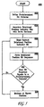
- FIG. 5 shows a flowchart of a method 400 according to the present invention for determining a rotational position of a magnetic storage medium divided into a plurality of servo sections.
- a predetermined bit pattern is defined that corresponds to a known position of magnetic storage medium.
- a rotational position indicator bit is associated with each servo section such that a known bit of the predetermined bit pattern is associated with the known position of the magnetic storage medium.
- a current rotational position indicator bit is read from the magnetic storage medium and, at step 408, a rotational position bit sequence comprising the current rotational position indicator bit is formed.
- the rotational position bit sequence is compared with the predetermined bit pattern and, at step 412, based on the comparison, it is determined whether the magnetic medium is at the known position.
Applications Claiming Priority (2)
| Application Number | Priority Date | Filing Date | Title |
|---|---|---|---|
| US09/372,354 US6320712B1 (en) | 1999-06-23 | 1999-08-11 | Apparatus and methods for low overhead highly reliable determination of rotational position of a magnetic storage medium |
| US372354 | 1999-08-11 |
Publications (2)
| Publication Number | Publication Date |
|---|---|
| EP1076338A2 true EP1076338A2 (fr) | 2001-02-14 |
| EP1076338A3 EP1076338A3 (fr) | 2002-12-18 |
Family
ID=23467795
Family Applications (1)
| Application Number | Title | Priority Date | Filing Date |
|---|---|---|---|
| EP00402230A Withdrawn EP1076338A3 (fr) | 1999-08-11 | 2000-08-04 | Appareil et méthode de détermination de la position angulaire d'un support d'enregistrement magnétique à faible sollicitation du système et très sure |
Country Status (4)
| Country | Link |
|---|---|
| US (1) | US6320712B1 (fr) |
| EP (1) | EP1076338A3 (fr) |
| JP (1) | JP2001076449A (fr) |
| TW (1) | TW479234B (fr) |
Cited By (1)
| Publication number | Priority date | Publication date | Assignee | Title |
|---|---|---|---|---|
| US20150381924A1 (en) * | 2013-03-06 | 2015-12-31 | Fujifilm Corporation | Lens device and position detection method of movable optical element |
Families Citing this family (3)
| Publication number | Priority date | Publication date | Assignee | Title |
|---|---|---|---|---|
| US20030161067A1 (en) * | 2002-02-27 | 2003-08-28 | Seagate Technlogy Llc | Determining head position during a head switch using multiple index codes |
| US7242546B2 (en) * | 2003-10-13 | 2007-07-10 | Seagate Technology Llc | Determining a location based on a cyclic bit sequence containing consecutively-placed identical bit-groups |
| US10089189B2 (en) * | 2016-04-15 | 2018-10-02 | Motorola Solutions, Inc. | Devices and methods for receiving a data file in a communication system |
Citations (4)
| Publication number | Priority date | Publication date | Assignee | Title |
|---|---|---|---|---|
| US5313340A (en) * | 1991-01-23 | 1994-05-17 | Hitachi, Ltd. | Read/write controlling apparatus for adjusting the data length of a magnetic disk |
| EP0667614A1 (fr) * | 1994-02-02 | 1995-08-16 | Fujitsu Limited | Unité à disque qui effectue un contrôle en utilisant des impulsions de sector |
| US5627695A (en) * | 1995-01-12 | 1997-05-06 | Qlogic Corporation | System and method for generating unique sector identifiers for an identificationless disk format |
| US5852523A (en) * | 1996-06-06 | 1998-12-22 | Samsung Electronics Co., Ltd. | Data sector pulse generating method |
Family Cites Families (3)
| Publication number | Priority date | Publication date | Assignee | Title |
|---|---|---|---|---|
| US5210660A (en) | 1990-01-17 | 1993-05-11 | International Business Machines Corporation | Sectored servo independent of data architecture |
| US5311376A (en) * | 1991-06-11 | 1994-05-10 | Western Digital (Singapore) Pte | Information detecting system |
| US5587850A (en) * | 1994-08-26 | 1996-12-24 | Quantum Corporation | Data track pattern including embedded servo sectors for magneto-resistive read/inductive write head structure for a disk drive |
-
1999
- 1999-08-11 US US09/372,354 patent/US6320712B1/en not_active Expired - Lifetime
-
2000
- 2000-08-01 TW TW089115376A patent/TW479234B/zh active
- 2000-08-04 EP EP00402230A patent/EP1076338A3/fr not_active Withdrawn
- 2000-08-10 JP JP2000242312A patent/JP2001076449A/ja active Pending
Patent Citations (4)
| Publication number | Priority date | Publication date | Assignee | Title |
|---|---|---|---|---|
| US5313340A (en) * | 1991-01-23 | 1994-05-17 | Hitachi, Ltd. | Read/write controlling apparatus for adjusting the data length of a magnetic disk |
| EP0667614A1 (fr) * | 1994-02-02 | 1995-08-16 | Fujitsu Limited | Unité à disque qui effectue un contrôle en utilisant des impulsions de sector |
| US5627695A (en) * | 1995-01-12 | 1997-05-06 | Qlogic Corporation | System and method for generating unique sector identifiers for an identificationless disk format |
| US5852523A (en) * | 1996-06-06 | 1998-12-22 | Samsung Electronics Co., Ltd. | Data sector pulse generating method |
Cited By (2)
| Publication number | Priority date | Publication date | Assignee | Title |
|---|---|---|---|---|
| US20150381924A1 (en) * | 2013-03-06 | 2015-12-31 | Fujifilm Corporation | Lens device and position detection method of movable optical element |
| US9503676B2 (en) * | 2013-03-06 | 2016-11-22 | Fujifilm Corporation | Lens device and position detection method of movable optical element |
Also Published As
| Publication number | Publication date |
|---|---|
| JP2001076449A (ja) | 2001-03-23 |
| EP1076338A3 (fr) | 2002-12-18 |
| TW479234B (en) | 2002-03-11 |
| US6320712B1 (en) | 2001-11-20 |
Similar Documents
| Publication | Publication Date | Title |
|---|---|---|
| JP2764097B2 (ja) | ディスクおよびディスクからデータを読出す方法、ならびにディスクを初期設定するための方法 | |
| US5940233A (en) | Method for detecting redundant nonadjacent synchronization bytes | |
| US4656532A (en) | Sector identification method for hard sectored hard files | |
| AU638905B2 (en) | Servo tracking for helical scan recorder | |
| CA2152689C (fr) | Appareil d'enregistrement de disques magnetiques a densite fixe et mecanisme d'acces aux donnees enregistrees | |
| US5589998A (en) | Cylinder address storage in multiple servo sectors of a track | |
| US6049438A (en) | Method and apparatus for encoding digital servo information in a servo burst | |
| JPH05174498A (ja) | 固定ブロック方式のディスク・ファイルのためのセクタ・アーキテクチャ | |
| US6462898B2 (en) | Disk drive with information encoded in the position error signal fields | |
| US5903404A (en) | High density disk unit and disk medium | |
| US6327105B1 (en) | Apparatus and methods for low overhead, highly reliable determination of position of a magnetic storage medium | |
| US6950265B2 (en) | Method and apparatus for servo defect management | |
| US5864440A (en) | Data processing method and data storage system | |
| WO1998016920A9 (fr) | Technique permettant de reduire les donnees de service dans un systeme de stockage de donnees | |
| WO1998016920A1 (fr) | Technique permettant de reduire les donnees de service dans un systeme de stockage de donnees | |
| US6320712B1 (en) | Apparatus and methods for low overhead highly reliable determination of rotational position of a magnetic storage medium | |
| US6141176A (en) | Data storage disk with information encoded in the position error signal fields | |
| US6259577B1 (en) | Method and apparatus for organizing servo data to expand data region and counting sector numbers from headerless servo format in a disk drive | |
| US6496312B2 (en) | Use of snake-in-the-box codes for reliable identification of tracks in servo fields of a disk drive | |
| US6337779B1 (en) | Disc-like recording medium, disc drive, and method for reading disc-like recording medium | |
| KR100273750B1 (ko) | 하드디스크드라이브의헤드위치검출방법 | |
| JP2002515622A (ja) | 長手方向位置情報が書き込まれたテープサーボパターン | |
| JPH0724145B2 (ja) | アドレス信号再生方法 |
Legal Events
| Date | Code | Title | Description |
|---|---|---|---|
| PUAI | Public reference made under article 153(3) epc to a published international application that has entered the european phase |
Free format text: ORIGINAL CODE: 0009012 |
|
| AK | Designated contracting states |
Kind code of ref document: A2 Designated state(s): AT BE CH CY DE DK ES FI FR GB GR IE IT LI LU MC NL PT SE |
|
| AX | Request for extension of the european patent |
Free format text: AL;LT;LV;MK;RO;SI |
|
| PUAL | Search report despatched |
Free format text: ORIGINAL CODE: 0009013 |
|
| AK | Designated contracting states |
Kind code of ref document: A3 Designated state(s): AT BE CH CY DE DK ES FI FR GB GR IE IT LI LU MC NL PT SE |
|
| AX | Request for extension of the european patent |
Free format text: AL;LT;LV;MK;RO;SI |
|
| AKX | Designation fees paid | ||
| REG | Reference to a national code |
Ref country code: DE Ref legal event code: 8566 |
|
| STAA | Information on the status of an ep patent application or granted ep patent |
Free format text: STATUS: THE APPLICATION IS DEEMED TO BE WITHDRAWN |
|
| 18D | Application deemed to be withdrawn |
Effective date: 20030619 |