EP1076118A1 - Method and an apparatus for casting a directionally solidified article - Google Patents
Method and an apparatus for casting a directionally solidified article Download PDFInfo
- Publication number
- EP1076118A1 EP1076118A1 EP00810575A EP00810575A EP1076118A1 EP 1076118 A1 EP1076118 A1 EP 1076118A1 EP 00810575 A EP00810575 A EP 00810575A EP 00810575 A EP00810575 A EP 00810575A EP 1076118 A1 EP1076118 A1 EP 1076118A1
- Authority
- EP
- European Patent Office
- Prior art keywords
- shell mold
- nozzle
- heating chamber
- casting
- cooling chamber
- Prior art date
- Legal status (The legal status is an assumption and is not a legal conclusion. Google has not performed a legal analysis and makes no representation as to the accuracy of the status listed.)
- Granted
Links
Images

Classifications
-
- B—PERFORMING OPERATIONS; TRANSPORTING
- B22—CASTING; POWDER METALLURGY
- B22D—CASTING OF METALS; CASTING OF OTHER SUBSTANCES BY THE SAME PROCESSES OR DEVICES
- B22D27/00—Treating the metal in the mould while it is molten or ductile ; Pressure or vacuum casting
- B22D27/04—Influencing the temperature of the metal, e.g. by heating or cooling the mould
- B22D27/045—Directionally solidified castings
-
- C—CHEMISTRY; METALLURGY
- C30—CRYSTAL GROWTH
- C30B—SINGLE-CRYSTAL GROWTH; UNIDIRECTIONAL SOLIDIFICATION OF EUTECTIC MATERIAL OR UNIDIRECTIONAL DEMIXING OF EUTECTOID MATERIAL; REFINING BY ZONE-MELTING OF MATERIAL; PRODUCTION OF A HOMOGENEOUS POLYCRYSTALLINE MATERIAL WITH DEFINED STRUCTURE; SINGLE CRYSTALS OR HOMOGENEOUS POLYCRYSTALLINE MATERIAL WITH DEFINED STRUCTURE; AFTER-TREATMENT OF SINGLE CRYSTALS OR A HOMOGENEOUS POLYCRYSTALLINE MATERIAL WITH DEFINED STRUCTURE; APPARATUS THEREFOR
- C30B11/00—Single-crystal growth by normal freezing or freezing under temperature gradient, e.g. Bridgman-Stockbarger method
-
- C—CHEMISTRY; METALLURGY
- C30—CRYSTAL GROWTH
- C30B—SINGLE-CRYSTAL GROWTH; UNIDIRECTIONAL SOLIDIFICATION OF EUTECTIC MATERIAL OR UNIDIRECTIONAL DEMIXING OF EUTECTOID MATERIAL; REFINING BY ZONE-MELTING OF MATERIAL; PRODUCTION OF A HOMOGENEOUS POLYCRYSTALLINE MATERIAL WITH DEFINED STRUCTURE; SINGLE CRYSTALS OR HOMOGENEOUS POLYCRYSTALLINE MATERIAL WITH DEFINED STRUCTURE; AFTER-TREATMENT OF SINGLE CRYSTALS OR A HOMOGENEOUS POLYCRYSTALLINE MATERIAL WITH DEFINED STRUCTURE; APPARATUS THEREFOR
- C30B29/00—Single crystals or homogeneous polycrystalline material with defined structure characterised by the material or by their shape
- C30B29/10—Inorganic compounds or compositions
- C30B29/52—Alloys
Definitions
- the invention relates to a method and an apparatus for casting a directionally solidified article.
- the Liquid Metal Cooling Process is a well known variation of the investment casting directional solidification process in which a shell mold which forms a cavity resembling the final part to be manufactured is filled with a liquid alloy, and lowered from a hot zone into a cold zone.
- the hot zone is usually maintained at above the temperature of solidification of the alloy being used and the cold zone is well below this temperature.
- solidification occurs directionally beginning with the first portion of the mold to enter the cold zone.
- the mold may be supported on a chill plate used for a structural base and also to rapidly remove heat from the bottom-most portions of the casting.
- the typical Bridgman process uses a water-cooled copper or steel lined vacuum chamber as a means of cooling the shell mold by radiation.
- a baffle made of an insulating material between the cold zone and hot zone which prevents excessive heat flow between them.
- the baffle is shaped so as let the shell mold pass through it with only a minimum amount of clearance space between the mold and the baffle. This further minimizes heat flow from hot zone to cold zone, maintains the solidification front of the material in the shell mold at a level close to that of the baffle, which is desirable, and maximizes the thermal gradient across the solidification front.
- the Bridgman and LMC directional solidification processes are used mostly today for the industrial production of columnar grained and single crystal articles destined for high temperature service and composed of Ni-based superalloys.
- Those familiar with the solidification of Ni based superalloys understand the great advantages of the higher gradients across the solidification front achieved during the LMC process: as outlined by Giamei and Tschinkel in Metallurgical Transactions A Volume 7A Sept 1976, pgs 1427-1434, these lead to finer dendrite arm spacings, smaller pores, the suppression of freckle defects, and smaller diffusion distances required during solution heat treatment.
- the effect of high gradient solidification on the lifetime of single crystal Ni based superalloys is well known.
- CMSX-2 exhibits approximately a doubling in Low Cycle Fatigue life and an order of magnitude improvement in creep rupture life at 870°C when solidified with a high gradient process compared to a low gradient process (p.1005, "Directionally Solidified and Single Crystal Superalloys" - The Metals handbook, Tenth Edition, Volume 1, ASM International 1990).
- a Method of casting a directionally solidified article with a casting furnace comprising a heating chamber, a liquid cooling bath as a cooling chamber and a shell mold, whereby the shell mold is fed with liquid metal, and withdrawn from the heating chamber to the cooling chamber, characterised in that the method takes place in an inert atmosphere of Ar and/or He in the pressure range of 0.01 to 1 atmosphere.
- the method will work the most advantageously at a preferred range of 0.05 to 0.25 atmosphere pressure and with a preferred gas mixture of between He and Ar with (vol.-%) 60 - 100 % He.
- the gas will be provided from a nozzle under or above the baffle between the heating chamber and the cooling chamber.
- the present invention relates a method and a apparatus of manufacturing a directionally solidified articles using an Liquid Metal Cooling (LMC)-process.
- LMC Liquid Metal Cooling
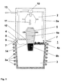
- Figure 1 shows a casting furnace 1 comprising heating chamber 2 and cooling chamber 3.
- the heating chamber 2 includes heating elements 2a. Both the heating chamber 2 and the cooling chamber 3 are separated by a baffle 4.
- the cooling chamber 3 use as a coolant a liquid metal bath such for example as aluminium at a temperature range between 700° and 900°C or a liquid tin bath at a range of 300°-500°C. For reasons of keeping the temperature in the mentioned range there may be around the cooling chamber 3 cooling elements 3a arranged.
- a shell mold 5 placed within the heating chamber 2 will be filled with a liquid alloy 6a through a feed opening 10 at the top of the heating chamber 2.
- the shell mold 5 is in the heating chamber 2 in a position which is shown with a dotted line. After filling the shell mold 5 it is withdrawn continuously from the heating chamber 2 to the cooling chamber 3 through an aperture 12 in the baffle 4. The direction of withdrawal 11 is indicated with an arrow. As soon as the shell mold 5 reaches the cooling chamber 2 solidification of the liquid alloy 6a begins. The solidified alloy 6b is found at the lower portion of the shell mold 5, which already reached the cold zone. Approximately at the border between the heating chamber 2 and the cooling chamber 3 is the solidification front 14. The solification front 14 grows from the bottom of the shell mold 5 to the top in opposite direction of the withdrawal direction 11.
- the average primary dendrite arm spacing was reduced from 390 ⁇ m (conventional) to 321 ⁇ m (invention). It is understood that this indicates a substantial increase in thermal gradient across the solidification front 14 during casting. This result will allow a higher withdrawal rate, suppress freckle defects, and lead to longer low cycle fatigue (LCF) and high cycle fatigue (HCF) lives of the cast article.
- LCF low cycle fatigue
- HCF high cycle fatigue
- microporosity was reduced from 0.25% (conventional) to 0.17% (invention). Less microporosity is well known to lead to significant improvements in HCF, LCF and creep rupture lives.
- the average diameter of micropore observed was decreased from 9.77 ⁇ m (conventional) to 8.63 ⁇ m (invention) with the largest micropore decreased from 76.5 ⁇ m to 60.0 ⁇ m. Again, it is understood that not only volume fraction porosity matters for HCF, LCF and creep lives, but also the size of the pores and the size of the single largest pores.
- the LMC process according the invention offers real lifetime advantages for the cast article over the conventional LMC using vacuum atmosphere.
- gas - in particulary the pure He or a mixture of He and Ar, preferable with (vol.-%) 60-100% He increases heat transfer very significantly compared to the case of LMC casting in a vacuum which is state of the art.
- Preliminary experiments showed that no significant benefits in casting results occurred at pressures over 0.25 atmosphere, however significant problems with furnace control equipment may occur as gas pressure rises due to the effect of gas convection on the furnace control thermocouples. In principle it is possible to let the inert gas in at any point of the casting furncace 1 through any inlet.
- FIG. 1 shows a preferred embodiment using a nozzle 7 which is connected with a feeding line 9 and which is in the left side of the figure 1 arranged under the baffle 4.
- the nozzle 7 directs a flow 8 of the inert gas against the shell mold 5 increasing the temperature gradient at the solidification front 14.
- a gas outlet 13 is provided for regulation of the pressure within the heating chamber 2 .
- a floating baffle 4a is provided on top of the liquid metal bath.
- the nozzle 4 with the feeding line 9 is arranged above the floating baffle 4a.
- the number of the nozzles 4 shown in figure 1 is only for example reasons and will not limit the extent of the invention.
- Figure 2 shows a second embodiment of a casting furnace 1 for carrying out the method according the invention.
- the feeding of the shell mold 5 and the withdrawal from the heating chamber 2 to the cooling chamber 3 is the same as specified in figure 1.
- the inert gas will be fed through a nozzle 15 located at the bottom of the liquid cooling bath 3.
- the nozzle 15, as an example a porous refractory nozzle, may be centered in the middle of the cooling chamber 3 under the shell mold 5.
Landscapes
- Chemical & Material Sciences (AREA)
- Engineering & Computer Science (AREA)
- Crystallography & Structural Chemistry (AREA)
- Materials Engineering (AREA)
- Metallurgy (AREA)
- Organic Chemistry (AREA)
- Mechanical Engineering (AREA)
- Inorganic Chemistry (AREA)
- Crystals, And After-Treatments Of Crystals (AREA)
- Manufacture And Refinement Of Metals (AREA)
Abstract
Description
- The invention relates to a method and an apparatus for casting a directionally solidified article.
- The Liquid Metal Cooling Process (LMC) is a well known variation of the investment casting directional solidification process in which a shell mold which forms a cavity resembling the final part to be manufactured is filled with a liquid alloy, and lowered from a hot zone into a cold zone. The hot zone is usually maintained at above the temperature of solidification of the alloy being used and the cold zone is well below this temperature. As the mold is drawn at a controlled rate into the cold zone, solidification occurs directionally beginning with the first portion of the mold to enter the cold zone. The mold may be supported on a chill plate used for a structural base and also to rapidly remove heat from the bottom-most portions of the casting. The typical Bridgman process (disclosed in the document US 1,793,672) uses a water-cooled copper or steel lined vacuum chamber as a means of cooling the shell mold by radiation. There is a baffle made of an insulating material between the cold zone and hot zone which prevents excessive heat flow between them. The baffle is shaped so as let the shell mold pass through it with only a minimum amount of clearance space between the mold and the baffle. This further minimizes heat flow from hot zone to cold zone, maintains the solidification front of the material in the shell mold at a level close to that of the baffle, which is desirable, and maximizes the thermal gradient across the solidification front.
- The LMC process as disclosed in US 3,763,926 uses a liquid medium (usually aluminum or tin) kept at a controlled temperature as the cold zone. While Patent US 3,763,926 discloses a stationary baffle similar to that used in the Bridgman process, a variation of this, using a baffle which floats on the surface of the liquid coolant, is disclosed in US 4,108,236. Those familiar with the art of directional solidification understand that the rate of heat transfer achievable at the surface of the shell mold is much greater when using liquid metal as a coolant than simply relying on radiation cooling in vacuum. It can be shown by calculations that the effect is 70% - 100% greater heat transfer away from the shell mold surface compared to pure radiation heat transfer.
- The Bridgman and LMC directional solidification processes are used mostly today for the industrial production of columnar grained and single crystal articles destined for high temperature service and composed of Ni-based superalloys. Those familiar with the solidification of Ni based superalloys understand the great advantages of the higher gradients across the solidification front achieved during the LMC process: as outlined by Giamei and Tschinkel in Metallurgical Transactions A Volume 7A Sept 1976, pgs 1427-1434, these lead to finer dendrite arm spacings, smaller pores, the suppression of freckle defects, and smaller diffusion distances required during solution heat treatment. The effect of high gradient solidification on the lifetime of single crystal Ni based superalloys is well known. One example, the commercially available CMSX-2, exhibits approximately a doubling in Low Cycle Fatigue life and an order of magnitude improvement in creep rupture life at 870°C when solidified with a high gradient process compared to a low gradient process (p.1005, "Directionally Solidified and Single Crystal Superalloys" - The Metals handbook, Tenth Edition,
Volume 1, ASM International 1990). - However, it is also well known in the industry that there are relatively few LMC furnaces in production compared to the very numerous Bridgman furnaces. One reason for this is the very high cost of the LMC furnace: maintaining a bath of liquid aluminum or tin at a controlled temperature is very complicated and costly. The high cost offsets the improvements in material properties achieved by using the process in most cases. One way to improve this situation would be to increase the production rate at which components are cast using the LMC process. As outlined by Giamei and Tschinkel, as the rate of withdrawal of the shell mold from the hot zone into the liquid coolant increases, so does the curvature of the solidification front. This is highly undesirable (leading to freckle defects and other problems) and so places an upper limit on the rate of withdrawal and hence the production rate of LMC cast components. What is needed is a means of avoiding this solidification front curvature at higher withdrawal rates, and generally increasing the amount of heat transfer in the process, in order to increase production rates using LMC and hence lower the cost of the process and further improve material properties.
- It is object of the present invention to find a method and an apparatus for manufacturing a directionally solidified articles using a LMC process overcoming the disadvantages described above and enhancing the LMC process (higher withdrawal rate, temperature gradient) without solidification front curvature.
- According to the invention a Method of casting a directionally solidified article with a casting furnace comprising a heating chamber, a liquid cooling bath as a cooling chamber and a shell mold, whereby the shell mold is fed with liquid metal, and withdrawn from the heating chamber to the cooling chamber, characterised in that the method takes place in an inert atmosphere of Ar and/or He in the pressure range of 0.01 to 1 atmosphere. The method will work the most advantageously at a preferred range of 0.05 to 0.25 atmosphere pressure and with a preferred gas mixture of between He and Ar with (vol.-%) 60 - 100 % He.
- In another embodiment the gas will be provided from a nozzle under or above the baffle between the heating chamber and the cooling chamber. The surprising discovery was made that using a casting furnace with a liquid metal bath as cooling medium a controlled pressure of the inert gas enhances the heat transfer between the shell mold and the liquid coolant greatly and increased the production rate substantially without solidification front curvature. It is also possible to introduce the gas within the liquid cooling bath using porous nozzles enhancing the method of solidification and at the same time inducing convection currents within the liquid cooling bath, which further enhances heat transfer.
- It is shown by
- Fig. 1
- a first embodiment of a LMC casting furnace according to the invention, with a nozzle under/above the baffle between the heating chamber and cooling chamber and
- Fig. 2
- a second embodiment of a LMC casting furnace according to the invention, with a nozzle at the bottom of the cooling chamber and immersed in the liquid coolant.
- The drawings show only the elements important for the invention. Same elements will be numbered in the same ways in different drawings.
- The present invention relates a method and a apparatus of manufacturing a directionally solidified articles using an Liquid Metal Cooling (LMC)-process.
- Figure 1 shows a
casting furnace 1 comprisingheating chamber 2 andcooling chamber 3. Theheating chamber 2 includesheating elements 2a. Both theheating chamber 2 and thecooling chamber 3 are separated by abaffle 4. Thecooling chamber 3 use as a coolant a liquid metal bath such for example as aluminium at a temperature range between 700° and 900°C or a liquid tin bath at a range of 300°-500°C. For reasons of keeping the temperature in the mentioned range there may be around thecooling chamber 3cooling elements 3a arranged. In the first step of the method for solidifying the directionally solidified article ashell mold 5 placed within theheating chamber 2 will be filled with aliquid alloy 6a through a feed opening 10 at the top of theheating chamber 2. Theshell mold 5 is in theheating chamber 2 in a position which is shown with a dotted line. After filling theshell mold 5 it is withdrawn continuously from theheating chamber 2 to thecooling chamber 3 through anaperture 12 in thebaffle 4. The direction ofwithdrawal 11 is indicated with an arrow. As soon as theshell mold 5 reaches thecooling chamber 2 solidification of theliquid alloy 6a begins. Thesolidified alloy 6b is found at the lower portion of theshell mold 5, which already reached the cold zone. Approximately at the border between theheating chamber 2 and thecooling chamber 3 is thesolidification front 14. Thesolification front 14 grows from the bottom of theshell mold 5 to the top in opposite direction of thewithdrawal direction 11. - The surprising discovery that was made, was that when using a
casting furnace 1 with aliquid metal bath 3 as a cooling medium, a controlled pressure of inert gas greatly enhances the heat transfer across theshell mold 5 and increases the production rate substantially withoutsolidifcation front 14 curvature. - Experimentation has shown that using inert gas such as Ar or He in the pressure range of 0.01 to 1 atmosphere, in a more preferred range of 0.05 - 0.25 atmosphere, substantially enhances the heat transfer during the LMC process. Tab.1 shows the different results for manufacturing two identical turbine blade-like castings, one cast with conventionally LMC in a vacuum atmosphere, the other using a He atmosphere in the more preferred range of 0.1 to 0.25 atmosphere. In both cases as coolant a aluminium bath was used, and the alloy was a commercially available Ni based single crystal superalloy.
-
Typ Average Primary dendrite arm spacing Average Microporosity Average micropore diameter Largest micropore diameter Conventional LMC 390 µm 0.25 % 9.77 µm 76.5 µm LMC according to invention 321 µm 0.17 % 8.63 µm 60 µm - The average primary dendrite arm spacing was reduced from 390 µm (conventional) to 321 µm (invention). It is understood that this indicates a substantial increase in thermal gradient across the
solidification front 14 during casting. This result will allow a higher withdrawal rate, suppress freckle defects, and lead to longer low cycle fatigue (LCF) and high cycle fatigue (HCF) lives of the cast article. - The average microporosity was reduced from 0.25% (conventional) to 0.17% (invention). Less microporosity is well known to lead to significant improvements in HCF, LCF and creep rupture lives.
- The average diameter of micropore observed was decreased from 9.77 µm (conventional) to 8.63 µm (invention) with the largest micropore decreased from 76.5 µm to 60.0 µm. Again, it is understood that not only volume fraction porosity matters for HCF, LCF and creep lives, but also the size of the pores and the size of the single largest pores.
- From these facts it is clear that the LMC process according the invention offers real lifetime advantages for the cast article over the conventional LMC using vacuum atmosphere. The presence of gas - in particulary the pure He or a mixture of He and Ar, preferable with (vol.-%) 60-100% He, increases heat transfer very significantly compared to the case of LMC casting in a vacuum which is state of the art. Preliminary experiments showed that no significant benefits in casting results occurred at pressures over 0.25 atmosphere, however significant problems with furnace control equipment may occur as gas pressure rises due to the effect of gas convection on the furnace control thermocouples. In principle it is possible to let the inert gas in at any point of the
casting furncace 1 through any inlet. - In addition to these general rules Fig. 1 shows a preferred embodiment using a
nozzle 7 which is connected with afeeding line 9 and which is in the left side of the figure 1 arranged under thebaffle 4. Thenozzle 7 directs aflow 8 of the inert gas against theshell mold 5 increasing the temperature gradient at thesolidification front 14. For regulation of the pressure within theheating chamber 2 agas outlet 13 is provided. As shown in the right side of figure 1 it is also possible to arrange a floatingbaffle 4a on top of the liquid metal bath. Thenozzle 4 with thefeeding line 9 is arranged above the floatingbaffle 4a. The number of thenozzles 4 shown in figure 1 is only for example reasons and will not limit the extent of the invention. - Figure 2 shows a second embodiment of a
casting furnace 1 for carrying out the method according the invention. In general the feeding of theshell mold 5 and the withdrawal from theheating chamber 2 to thecooling chamber 3 is the same as specified in figure 1. But as a difference during the solidification of theliquid alloy 6a the inert gas will be fed through anozzle 15 located at the bottom of theliquid cooling bath 3. Thenozzle 15, as an example a porous refractory nozzle, may be centered in the middle of thecooling chamber 3 under theshell mold 5. With this embodiment not only the advantages during the solidification are achieved as described above but aflow 16 will induce a convection current 18 with no moving parts. This is a further advantage over the patent US 3,763,926 in which a mechanical stirrer is used for generation a current to enhance the heat transfer by ensuring a homogenous temperature within the liquid metal bath. As seen in figure 2 the inert gas will separated in small bubbles 17. Thisnozzle 15 may be located at the bottom of the liquid coolant bath either centered or at the side, or on the vertical walls of the bath in order to induce convection currents as desired. There may also be more than one immersed nozzle. It is understood that the location of thenozzles 15 and the number ofnozzles 15 that will optimise fluid flow and gas introduction will vary as a function of the shape and size of the shell mold being used. -
- 1
- Casting furnace
- 2
- Heating chamber
- 2a
- Heating elements
- 3
- Cooling chamber, liquid metal bath
- 3a
- Cooling Elements
- 4
- Baffle
- 4a
- Floating baffle
- 5
- Shell mold
- 6a
- Liquid alloy
- 6b
- solidified alloy
- 7
- Nozzle
- 8
- flow
- 9
- Feed line
- 10
- Feed opening
- 11
- Direction of withdrawal
- 12
- Aperture
- 13
- Outlet
- 14
- Solidification front
- 15
- nozzle
- 16
- flow
- 17
- bubble
- 18
- current
Claims (12)
- Method of casting a directionally solidified article with a casting furnace (1) comprising a heating chamber (2), a liquid cooling bath (3) as a cooling chamber (3) and a shell mold (5), whereby the shell mold (5) is fed with liquid metal (6a), and withdrawn from the heating chamber (2) to the cooling chamber (3),
characterised in that
the method takes place in an inert atmosphere of Ar and/or He in the pressure range of 0.01 to 1 atmosphere. - Process of claim 1,
characterised in that
the method takes place in an inert atmosphere of Ar and/or He with a pressure range of 0.05 to 0.25 atmosphere. - Process of claim 2,
characterised in that
the method takes place in an inert atmosphere of Ar and/or He with an atmosphere containing (vol.-%) 60% to 100% He. - Process of one of the claims 1 to 3,
characterised in that
the gas Ar and/or He is fed through an inlet at any point of the casting furnace (1) during the withdrawal of the shell mold (5). - Process of one of the claims 1 to 3,
characterised in that
the gas Ar and/or He is fed through a nozzle (7,15) towards the shell mold (5) during the withdrawal of the shell mold (5). - Process of claim 5,
characterised in that
the gas Ar and/or He is fed through a nozzle (7) towards the shell mold (5) under a baffle (4) which separates the heating chamber (2) and the cooling chamber (3) during the withdrawal of the shell mold (5). - Process of claim 4,
characterised in that
the gas Ar and/or He is fed through a nozzle (7) towards the shell mold (5) above a floating baffle (4a) which separates the heating chamber (2) and the cooling chamber (3) during the withdrawal of the shell mold (5). - Process of claim 4,
characterised in that
the gas Ar and/or He is fed through a nozzle (15) immersed liquid cooling bath (3) during the withdrawal of the shell mold (5). - Casting furnace (1) for carrying out the method of claim 1 to 8 comprising a heating chamber (2), a liquid cooling bath (3) as a cooling chamber (3) and a shell mold (5),
characterised in that
at least one nozzle (7,15) is provided which is directed toward the shell mold (3) at any place of the casting furnace (1). - Casting furnace (1) of claim 9,
characterised in that
at least one nozzle (7) is provided which is directed toward the shell mold (3) under a floating baffle (4a) which separates the heating chamber (2) and the cooling chamber (3). - Casting furnace (1) of claim 9,
characterised in that
at least one nozzle (7) is provided which is directed toward the shell mold (3) above a baffle which separates the heating chamber (2) and the cooling chamber (3). - Casting furnace (1) of claim 9,
characterised in that
at least one nozzle (15) is provided which is immersed in the liquid coolant in the cooling chamber (3).
Applications Claiming Priority (2)
| Application Number | Priority Date | Filing Date | Title |
|---|---|---|---|
| US373719 | 1995-01-17 | ||
| US09/373,719 US6311760B1 (en) | 1999-08-13 | 1999-08-13 | Method and apparatus for casting directionally solidified article |
Publications (2)
| Publication Number | Publication Date |
|---|---|
| EP1076118A1 true EP1076118A1 (en) | 2001-02-14 |
| EP1076118B1 EP1076118B1 (en) | 2005-09-07 |
Family
ID=23473582
Family Applications (1)
| Application Number | Title | Priority Date | Filing Date |
|---|---|---|---|
| EP00810575A Revoked EP1076118B1 (en) | 1999-08-13 | 2000-07-03 | Method for casting a directionally solidified article |
Country Status (3)
| Country | Link |
|---|---|
| US (1) | US6311760B1 (en) |
| EP (1) | EP1076118B1 (en) |
| DE (1) | DE60022444T2 (en) |
Cited By (8)
| Publication number | Priority date | Publication date | Assignee | Title |
|---|---|---|---|---|
| EP1531020A1 (en) * | 2003-11-06 | 2005-05-18 | ALSTOM Technology Ltd | Method for casting a directionally solidified article |
| EP1375034A3 (en) * | 2002-06-20 | 2005-06-22 | Howmet Research Corporation | Method and apparatus for directional solidification of a metal melt |
| EP2098314A1 (en) * | 2008-03-05 | 2009-09-09 | TITAL GmbH | Method and apparatus for producing metallic casting moulds using the lost wax casting method |
| CZ303307B6 (en) * | 2010-12-27 | 2012-07-25 | Vysoké ucení technické v Brne | Method of and device for providing controlled crystallization and cooling of castings, especially castings of aluminium and alloys thereof |
| EP2913417B1 (en) | 2014-02-28 | 2017-01-11 | General Electric Company | Article and method for forming article |
| EP3277451A1 (en) * | 2015-04-01 | 2018-02-07 | Saint Jean Industries | Sand shell-moulding method for the production of a part for use in the automotive and aeronautics fields |
| EP3335817A1 (en) * | 2016-12-19 | 2018-06-20 | General Electric Company | Casting method and cast article |
| US10265764B2 (en) | 2014-01-28 | 2019-04-23 | General Electric Company | Casting method and cast article |
Families Citing this family (17)
| Publication number | Priority date | Publication date | Assignee | Title |
|---|---|---|---|---|
| RU2226449C1 (en) * | 2002-11-18 | 2004-04-10 | Цацулина Ирина Евгеньевна | Method for casting parts with use of oriented crystallization and apparatus for performing the same |
| US6896030B2 (en) * | 2003-07-30 | 2005-05-24 | Howmet Corporation | Directional solidification method and apparatus |
| US7258158B2 (en) * | 2004-07-28 | 2007-08-21 | Howmet Corporation | Increasing stability of silica-bearing material |
| US20080257517A1 (en) * | 2005-12-16 | 2008-10-23 | General Electric Company | Mold assembly for use in a liquid metal cooled directional solidification furnace |
| US20090314452A1 (en) * | 2008-06-24 | 2009-12-24 | Garlock Robert M | Method of casting metal articles |
| US20100132906A1 (en) * | 2008-12-03 | 2010-06-03 | Graham Lawrence D | Method of casting a metal article |
| US8752611B2 (en) * | 2011-08-04 | 2014-06-17 | General Electric Company | System and method for directional casting |
| US10082032B2 (en) * | 2012-11-06 | 2018-09-25 | Howmet Corporation | Casting method, apparatus, and product |
| WO2015130371A2 (en) * | 2013-12-30 | 2015-09-03 | United Technologies Corporation | Directional solidification apparatus and related methods |
| US20150231696A1 (en) * | 2014-02-18 | 2015-08-20 | General Electric Company | Methods for directional solidification casting |
| PL222793B1 (en) * | 2014-03-13 | 2016-09-30 | Seco/Warwick Europe Spółka Z Ograniczoną Odpowiedzialnością | Method for the oriented crystallization of gas turbine blades and the device for producing castings of the gas turbine blades with oriented and monocrystalline structure |
| US9352384B2 (en) | 2014-05-27 | 2016-05-31 | Honda Motor Co., Ltd. | Cylinder head casting apparatus and methods |
| JP6604507B2 (en) * | 2015-11-19 | 2019-11-13 | 日立金属株式会社 | Turbine blade and method for manufacturing the same |
| CN113732272B (en) * | 2021-08-25 | 2022-06-03 | 中国联合重型燃气轮机技术有限公司 | Directional solidification device and directional solidification method |
| PL248000B1 (en) * | 2022-04-07 | 2025-09-29 | Seco/Warwick Spolka Akcyjna | Method and device for directional crystallization of castings with a directed or single-crystalline structure |
| US11833581B1 (en) * | 2022-09-07 | 2023-12-05 | General Electric Company | Heat extraction or retention during directional solidification of a casting component |
| US12325066B2 (en) | 2023-03-23 | 2025-06-10 | Rajeev Naik | Casting furnace for solidification restructuring (FSR) |
Citations (6)
| Publication number | Priority date | Publication date | Assignee | Title |
|---|---|---|---|---|
| FR2152649A1 (en) * | 1971-09-15 | 1973-04-27 | United Aircraft Corp | |
| US4862947A (en) * | 1988-08-02 | 1989-09-05 | Pcc Airfoils, Inc. | Method of casting an article |
| US5398745A (en) * | 1993-05-07 | 1995-03-21 | Pcc Composites, Inc. | Method of directionally cooling using a fluid pressure induced thermal gradient |
| WO1996005006A1 (en) * | 1994-08-08 | 1996-02-22 | Siemens Aktiengesellschaft | Method and device for directionally solidifiying a melt |
| EP0749790A1 (en) * | 1995-06-20 | 1996-12-27 | Abb Research Ltd. | Process for casting a directionally solidified article and apparatus for carrying out this process |
| EP0891828A1 (en) * | 1997-07-17 | 1999-01-20 | ALD Vacuum Technologies GmbH | Method and apparatus for directional solidification of a metal melt |
Family Cites Families (9)
| Publication number | Priority date | Publication date | Assignee | Title |
|---|---|---|---|---|
| US1793672A (en) | 1926-02-16 | 1931-02-24 | Percy W Bridgman | Crystals and their manufacture |
| US3690367A (en) * | 1968-07-05 | 1972-09-12 | Anadite Inc | Apparatus for the restructuring of metals |
| DE1953716C3 (en) * | 1968-10-28 | 1973-01-04 | Matsunaga, Yonosuke, Yokohama City (Japan) | Process for the production of an ingot |
| BE754962A (en) * | 1969-08-20 | 1971-02-01 | Western Electric Co | PROCESS FOR THE PRODUCTION OF SOLIDS BY ORIENTED SOLIDIFICATION |
| GB1374462A (en) * | 1971-06-22 | 1974-11-20 | Secr Defence | Casting of metal articles |
| FR2361181A1 (en) * | 1976-08-11 | 1978-03-10 | Onera (Off Nat Aerospatiale) | PROCESS AND APPARATUS FOR THE MOLDING OF SHAPED PARTS IN REFRACTORY COMPOSITE MATERIAL |
| US4108236A (en) | 1977-04-21 | 1978-08-22 | United Technologies Corporation | Floating heat insulating baffle for directional solidification apparatus utilizing liquid coolant bath |
| JPS5695464A (en) * | 1979-12-14 | 1981-08-01 | Secr Defence Brit | Directional coagulating method |
| DE4321640C2 (en) * | 1993-06-30 | 1998-08-06 | Siemens Ag | Process for the directional solidification of a molten metal and casting device for carrying it out |
-
1999
- 1999-08-13 US US09/373,719 patent/US6311760B1/en not_active Expired - Lifetime
-
2000
- 2000-07-03 EP EP00810575A patent/EP1076118B1/en not_active Revoked
- 2000-07-03 DE DE60022444T patent/DE60022444T2/en not_active Revoked
Patent Citations (6)
| Publication number | Priority date | Publication date | Assignee | Title |
|---|---|---|---|---|
| FR2152649A1 (en) * | 1971-09-15 | 1973-04-27 | United Aircraft Corp | |
| US4862947A (en) * | 1988-08-02 | 1989-09-05 | Pcc Airfoils, Inc. | Method of casting an article |
| US5398745A (en) * | 1993-05-07 | 1995-03-21 | Pcc Composites, Inc. | Method of directionally cooling using a fluid pressure induced thermal gradient |
| WO1996005006A1 (en) * | 1994-08-08 | 1996-02-22 | Siemens Aktiengesellschaft | Method and device for directionally solidifiying a melt |
| EP0749790A1 (en) * | 1995-06-20 | 1996-12-27 | Abb Research Ltd. | Process for casting a directionally solidified article and apparatus for carrying out this process |
| EP0891828A1 (en) * | 1997-07-17 | 1999-01-20 | ALD Vacuum Technologies GmbH | Method and apparatus for directional solidification of a metal melt |
Non-Patent Citations (2)
| Title |
|---|
| DEXIN MA ET AL: "EINKRISTALLERSTARRUNG DER NI-BASIS-SUPERLEGIERUNG SRR 99", ZEITSCHRIFT FUR METALLKUNDE,DE,DR.RIEDERER VERLAG GMBH. STUTTGART, vol. 82, no. 11, 1 November 1991 (1991-11-01), pages 869 - 873, XP000278142, ISSN: 0044-3093 * |
| FRAS E ET AL: "PROCESSING AND MICROSTRUCTURE OF INVESTMENT CASTING TURBINE BLADE NITAC IN-SITU COMPOSITES", JOURNAL OF MATERIALS ENGINEERING AND PERFORMANCE,US,ASM INTERNATIONAL, MATERIALS PARK, vol. 5, no. 1, 1 February 1996 (1996-02-01), pages 103 - 110, XP000554304, ISSN: 1059-9495 * |
Cited By (9)
| Publication number | Priority date | Publication date | Assignee | Title |
|---|---|---|---|---|
| EP1375034A3 (en) * | 2002-06-20 | 2005-06-22 | Howmet Research Corporation | Method and apparatus for directional solidification of a metal melt |
| EP1531020A1 (en) * | 2003-11-06 | 2005-05-18 | ALSTOM Technology Ltd | Method for casting a directionally solidified article |
| US7017646B2 (en) | 2003-11-06 | 2006-03-28 | Alstom Technology Ltd. | Method for casting a directionally solidified article |
| EP2098314A1 (en) * | 2008-03-05 | 2009-09-09 | TITAL GmbH | Method and apparatus for producing metallic casting moulds using the lost wax casting method |
| CZ303307B6 (en) * | 2010-12-27 | 2012-07-25 | Vysoké ucení technické v Brne | Method of and device for providing controlled crystallization and cooling of castings, especially castings of aluminium and alloys thereof |
| US10265764B2 (en) | 2014-01-28 | 2019-04-23 | General Electric Company | Casting method and cast article |
| EP2913417B1 (en) | 2014-02-28 | 2017-01-11 | General Electric Company | Article and method for forming article |
| EP3277451A1 (en) * | 2015-04-01 | 2018-02-07 | Saint Jean Industries | Sand shell-moulding method for the production of a part for use in the automotive and aeronautics fields |
| EP3335817A1 (en) * | 2016-12-19 | 2018-06-20 | General Electric Company | Casting method and cast article |
Also Published As
| Publication number | Publication date |
|---|---|
| EP1076118B1 (en) | 2005-09-07 |
| DE60022444T2 (en) | 2006-06-14 |
| US6311760B1 (en) | 2001-11-06 |
| DE60022444D1 (en) | 2005-10-13 |
Similar Documents
| Publication | Publication Date | Title |
|---|---|---|
| EP1076118B1 (en) | Method for casting a directionally solidified article | |
| EP2011588B1 (en) | Casting method | |
| US4573516A (en) | Method of and apparatus for casting directionally solidified articles | |
| US20110094705A1 (en) | Methods for centrifugally casting highly reactive titanium metals | |
| US20090133850A1 (en) | Systems for centrifugally casting highly reactive titanium metals | |
| US6798821B2 (en) | Method and apparatus for solidification-controllable induction melting of alloy with cold copper crucible | |
| US4515204A (en) | Continuous metal casting | |
| EP1531020B1 (en) | Method for casting a directionally solidified article | |
| EP0968065B1 (en) | Method and apparatus for producing directionally solidified castings | |
| EP0471798B1 (en) | Induction skull melt spinning of reactive metal alloys | |
| AU637447B2 (en) | Controlled casting of hypereutectic alloys | |
| CN105358723B (en) | Method for producing aluminum alloy containing lithium | |
| JP2001212662A (en) | Articles nucleated and cast from clean metal | |
| US3344840A (en) | Methods and apparatus for producing metal ingots | |
| JP2022129329A (en) | Unidirectional solidification device and unidirectional solidification method | |
| EP0209593B1 (en) | Continuous casting method | |
| US20240316626A1 (en) | Casting furnace for solidification restructuring (fsr) | |
| EP1502679B1 (en) | Method for casting a directionally solidified or single crystal article | |
| US6715534B1 (en) | Method and apparatus for producing directionally solidified castings | |
| WO2021024704A1 (en) | METHOD FOR CASTING Ti-AL BASED ALLOY | |
| US3455373A (en) | Apparatus for ultrahigh purity precision casting | |
| CN117845068B (en) | Method for removing impurity elements from nickel-based superalloy return material by electron beam melting | |
| SU532642A1 (en) | Aluminum Alloy Refining | |
| JP4366705B2 (en) | Ingot manufacturing method and apparatus | |
| JPH0970656A (en) | Production of metal and alloy cast block |
Legal Events
| Date | Code | Title | Description |
|---|---|---|---|
| PUAI | Public reference made under article 153(3) epc to a published international application that has entered the european phase |
Free format text: ORIGINAL CODE: 0009012 |
|
| AK | Designated contracting states |
Kind code of ref document: A1 Designated state(s): DE GB |
|
| AX | Request for extension of the european patent |
Free format text: AL;LT;LV;MK;RO;SI |
|
| 17P | Request for examination filed |
Effective date: 20010630 |
|
| RAP1 | Party data changed (applicant data changed or rights of an application transferred) |
Owner name: ABB (SCHWEIZ) AG |
|
| AKX | Designation fees paid |
Free format text: DE GB |
|
| RAP1 | Party data changed (applicant data changed or rights of an application transferred) |
Owner name: ALSTOM |
|
| RAP1 | Party data changed (applicant data changed or rights of an application transferred) |
Owner name: ALSTOM (SWITZERLAND) LTD |
|
| 17Q | First examination report despatched |
Effective date: 20030415 |
|
| RAP1 | Party data changed (applicant data changed or rights of an application transferred) |
Owner name: ALSTOM TECHNOLOGY LTD |
|
| GRAP | Despatch of communication of intention to grant a patent |
Free format text: ORIGINAL CODE: EPIDOSNIGR1 |
|
| RTI1 | Title (correction) |
Free format text: METHOD FOR CASTING A DIRECTIONALLY SOLIDIFIED ARTICLE |
|
| GRAP | Despatch of communication of intention to grant a patent |
Free format text: ORIGINAL CODE: EPIDOSNIGR1 |
|
| GRAS | Grant fee paid |
Free format text: ORIGINAL CODE: EPIDOSNIGR3 |
|
| GRAA | (expected) grant |
Free format text: ORIGINAL CODE: 0009210 |
|
| AK | Designated contracting states |
Kind code of ref document: B1 Designated state(s): DE GB |
|
| REG | Reference to a national code |
Ref country code: GB Ref legal event code: FG4D |
|
| REF | Corresponds to: |
Ref document number: 60022444 Country of ref document: DE Date of ref document: 20051013 Kind code of ref document: P |
|
| PLBI | Opposition filed |
Free format text: ORIGINAL CODE: 0009260 |
|
| 26 | Opposition filed |
Opponent name: SIEMENS AKTIENGESELLSCHAFT ABT. CT IP PG Effective date: 20060221 |
|
| PLAX | Notice of opposition and request to file observation + time limit sent |
Free format text: ORIGINAL CODE: EPIDOSNOBS2 |
|
| PLAF | Information modified related to communication of a notice of opposition and request to file observations + time limit |
Free format text: ORIGINAL CODE: EPIDOSCOBS2 |
|
| PLBB | Reply of patent proprietor to notice(s) of opposition received |
Free format text: ORIGINAL CODE: EPIDOSNOBS3 |
|
| PGFP | Annual fee paid to national office [announced via postgrant information from national office to epo] |
Ref country code: DE Payment date: 20070719 Year of fee payment: 8 |
|
| RDAF | Communication despatched that patent is revoked |
Free format text: ORIGINAL CODE: EPIDOSNREV1 |
|
| PGFP | Annual fee paid to national office [announced via postgrant information from national office to epo] |
Ref country code: GB Payment date: 20070720 Year of fee payment: 8 |
|
| RDAG | Patent revoked |
Free format text: ORIGINAL CODE: 0009271 |
|
| STAA | Information on the status of an ep patent application or granted ep patent |
Free format text: STATUS: PATENT REVOKED |
|
| 27W | Patent revoked |
Effective date: 20071211 |
|
| GBPR | Gb: patent revoked under art. 102 of the ep convention designating the uk as contracting state |
Effective date: 20071211 |
|
| PLAB | Opposition data, opponent's data or that of the opponent's representative modified |
Free format text: ORIGINAL CODE: 0009299OPPO |