EP1075980A1 - Current collector for a railway vehicle - Google Patents
Current collector for a railway vehicle Download PDFInfo
- Publication number
- EP1075980A1 EP1075980A1 EP00117441A EP00117441A EP1075980A1 EP 1075980 A1 EP1075980 A1 EP 1075980A1 EP 00117441 A EP00117441 A EP 00117441A EP 00117441 A EP00117441 A EP 00117441A EP 1075980 A1 EP1075980 A1 EP 1075980A1
- Authority
- EP
- European Patent Office
- Prior art keywords
- pantograph
- roof
- car body
- hydraulic
- rail vehicle
- Prior art date
- Legal status (The legal status is an assumption and is not a legal conclusion. Google has not performed a legal analysis and makes no representation as to the accuracy of the status listed.)
- Withdrawn
Links
Images


Classifications
-
- B—PERFORMING OPERATIONS; TRANSPORTING
- B60—VEHICLES IN GENERAL
- B60L—PROPULSION OF ELECTRICALLY-PROPELLED VEHICLES; SUPPLYING ELECTRIC POWER FOR AUXILIARY EQUIPMENT OF ELECTRICALLY-PROPELLED VEHICLES; ELECTRODYNAMIC BRAKE SYSTEMS FOR VEHICLES IN GENERAL; MAGNETIC SUSPENSION OR LEVITATION FOR VEHICLES; MONITORING OPERATING VARIABLES OF ELECTRICALLY-PROPELLED VEHICLES; ELECTRIC SAFETY DEVICES FOR ELECTRICALLY-PROPELLED VEHICLES
- B60L5/00—Current collectors for power supply lines of electrically-propelled vehicles
- B60L5/18—Current collectors for power supply lines of electrically-propelled vehicles using bow-type collectors in contact with trolley wire
- B60L5/22—Supporting means for the contact bow
- B60L5/28—Devices for lifting and resetting the collector
-
- B—PERFORMING OPERATIONS; TRANSPORTING
- B60—VEHICLES IN GENERAL
- B60L—PROPULSION OF ELECTRICALLY-PROPELLED VEHICLES; SUPPLYING ELECTRIC POWER FOR AUXILIARY EQUIPMENT OF ELECTRICALLY-PROPELLED VEHICLES; ELECTRODYNAMIC BRAKE SYSTEMS FOR VEHICLES IN GENERAL; MAGNETIC SUSPENSION OR LEVITATION FOR VEHICLES; MONITORING OPERATING VARIABLES OF ELECTRICALLY-PROPELLED VEHICLES; ELECTRIC SAFETY DEVICES FOR ELECTRICALLY-PROPELLED VEHICLES
- B60L5/00—Current collectors for power supply lines of electrically-propelled vehicles
- B60L5/18—Current collectors for power supply lines of electrically-propelled vehicles using bow-type collectors in contact with trolley wire
- B60L5/19—Current collectors for power supply lines of electrically-propelled vehicles using bow-type collectors in contact with trolley wire using arrangements for effecting collector movement transverse to the direction of vehicle motion
-
- B—PERFORMING OPERATIONS; TRANSPORTING
- B60—VEHICLES IN GENERAL
- B60L—PROPULSION OF ELECTRICALLY-PROPELLED VEHICLES; SUPPLYING ELECTRIC POWER FOR AUXILIARY EQUIPMENT OF ELECTRICALLY-PROPELLED VEHICLES; ELECTRODYNAMIC BRAKE SYSTEMS FOR VEHICLES IN GENERAL; MAGNETIC SUSPENSION OR LEVITATION FOR VEHICLES; MONITORING OPERATING VARIABLES OF ELECTRICALLY-PROPELLED VEHICLES; ELECTRIC SAFETY DEVICES FOR ELECTRICALLY-PROPELLED VEHICLES
- B60L2200/00—Type of vehicles
- B60L2200/26—Rail vehicles
Definitions
- the invention relates to a rail vehicle with at least a car body, on the roof of which there is at least one pantograph with its support electrically isolated and from the roof of the Car body is spaced apart, at least one Pantographs can be raised into an operating position and into a rest position is lowerable.
- Such rail vehicles have, if they are multi-system vehicles are executed for the different systems at least one pantograph. At least that is some of the pantographs on the roofs of car bodies arranged, which serve as passenger compartments. The same goes for for rail vehicles designed as multiple units, and so that there are no powered heads inaccessible to passengers.
- the clearance profile of the route to be traveled not to hurt and on the other hand at the deepest under part of the pantograph standing under electrical voltage The minimum air gap to the roof of the car body must be observed the roof of the car body in the area of the pantograph opposite the remaining area of the roof is usually lowered.
- the lowering of the roof leads to a reduced interior height.
- the roof height is usually reduced, among others determines the torsional rigidity of the car body.
- the object of the present invention is a rail vehicle of the type mentioned at the outset, on the one hand with regard to the structural design of the car body is not subject to any restrictions and on the other hand that Clearance profile of the routes to be traveled is not violated.
- the rail vehicle according to claim 1 comprises at least one Car body with at least one pantograph on the roof its support electrically insulated and the roof of the car body in front is arranged spaced apart, at least one pantograph can be raised into an operating position and into a rest position is lowerable.
- the carrier of the pantograph is by an adjusting device in its height distance to Roof of the car body so adjustable that in one Rested, lowered and electrically de-energized pantograph the height distance between the lowest under electrical Live part of the pantograph and the roof is less than the minimum air gap by a predeterminable difference value, and that with a raised in operational position and pantographs under voltage the height distance between the lowest under electrical Voltage part of the pantograph and the roof at least corresponds to the minimum air gap.
- the respective Safety distance of the pantograph from the roof of the car body adaptable to the respective operating cases. Is the pantograph lowered to its rest position and electrically de-energized then the height difference between the Carrier of the pantograph and the roof of the car body around a predefinable limit value smaller than the minimum air gap. However, the pantograph is in its operating position raised, then the height distance between the Carrier of the pantograph and the roof of the car body at least the minimum air gap. The pantograph can then safely connected to the electrical voltage (contact wire voltage) become.
- pantograph Since the working height of the pantograph is adjustable the maximum possible body height under the pantograph determined by the resting position of the pantograph. For rail vehicles, where the pantograph against the slope of the car body is traceable, is in addition to the rest position the pantograph still take into account its swivel position.
- the pantograph must counter the inclination of the car body to be led back. In this case it is special advantageous, the rail vehicle according to claim 2 or 3 to train.
- the actuating device can be an electro-mechanical Steep device (claim 4) or as an electro-pneumatic Actuating device (claim 5) formed his.
- the actuator can be used as an electro-hydraulic Actuating device (claim 6) or as an electro-pneumatic-hydraulic Actuating device (claim 7) formed his.
- a pantograph 3rd is arranged with its carrier 4.
- the carrier 4 shown in the Embodiment the deepest under electrical Representing live part is over three post insulators 5a, 5b and 5c (see FIG. 3) electrically insulated and from the roof 2 of the car body 1 arranged spaced.
- the pantograph 3 can be lowered into a rest position (FIG 1) and can be raised into an operating position (FIG. 2).
- the rail vehicle according to the invention has an actuating device 6 through which the carrier 4 of the pantograph 3 adjustable in height to the roof 2 of the car body 1 is.
- the steep device 6 as a lifting device trained and includes for each post insulator 5a, 5b and 5c each have a hydraulic cylinder 8a, 8b and 8c (see FIG 4).
- the hydraulic cylinders 8a, 8b and 8c are in the post insulators 5a, 5b and 5c integrated.
- the pantograph 3 If the pantograph 3 is raised to its operating position and is under electrical voltage, then the height distance H BL of the carrier 4 to the roof 2 of the car body 1 corresponds at least to the minimum air gap L. The pantograph 3 can then be safely connected to the electrical voltage. For this purpose, the contact strips 30 and 31 of the pantograph 3 (see FIG. 4) rest on the contact wire 32 (see FIG. 2).
- pantograph 3 has a telescopic apex tube 7 has, this can be used to further lower the pantograph 3 or shortened to reduce wind noise on Fit roof 2 of car body 1.
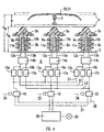
- the hydraulic steep device 6 shown in FIG. 4 comprises for each of the three post insulators 5a, 5b and 5c which the carrier 4 of the pantograph 3 on the roof 2nd of the car body 1 supports (see FIG. 4) one hydraulic each Actuator 8a or 8b or 8c.
- the hydraulic Actuators 8a and 8b and 8c are in the post insulators 5a, 5b and 5c integrated.
- the hydraulic actuators 8a, 8b and 8c each consist of a hydraulic cylinder 9a or 9b or 9c slim design, the piston rod 10a or 10b or 10c with the post insulator 5a or 5b or 5c connected is.
- the hydraulic actuator 8a or 8b or 8c is with the bottom of its housing 11a or 11b or 11c attached to the roof 2 of the car body 1.
- the hydraulic cylinders 10a, 10b and 10c By feeling the hydraulic cylinders 10a, 10b and 10c through their respective bottom inlet opening through a hydraulic line 12a 12b and 12c become the piston rods 10a, 10b and 10c extended (stroke volume of the hydraulic cylinders 9a, 9b and 9c increases) and thus the carrier 4 of the pantograph 3 is raised.
- the hydraulic cylinders can limit the existing kinetic energy 9a, 9b and 9c equipped with end position damping his.
- the hydraulic lines 12a and 13a connect the hydraulic cylinder 9a with a blocking device 14a and the hydraulic lines 12b and 13b connect the hydraulic cylinder 9b with a blocking device 14b. Furthermore connect the Hydraulic lines 12c and 13c with the hydraulic cylinder 9c a blocking device 14c.
- the blocking devices 14a, 14b and 14c prevent the carrier from dropping arbitrarily 4 of the pantograph 3.
- the blocking device 14a or 14b or 14c can also in the hydraulic actuator 8a or 8b or 8c can be integrated. In the simplest case they exist Blocking devices 14a, 14b and 14c made of simple or double acting check valves. But they can also be called hydraulic actuated clamping elements on the piston rods 10a, 10b and 10c act.
- the blocking device 14a is connected via hydraulic lines three flow valves 15a, 16a and 17a connected. Is analog the blocking device 14b via hydraulic lines with flow valves 15b, 16b and 17b and the blocking device 14c via hydraulic lines with flow valves 15c, 16c and 17c connected.
- the flow valves 15a to 17c are used to keep tracking while the wearer is moving 4 to improve the pantograph 3 again.
- the hydraulic control device 6 must be three in total different movements - namely lifting, lowering or rapid lowering of the carrier 4 - can perform.
- each of the three hydraulic actuators 8a, 8b and 8c three each the volume flow according to size and Flow valves 15a, 16a and 17a influencing the direction or 15b, 16b and 17b or 15c, 16c and 17c.
- these functions can also be used in the Hydraulic lines 21, 22 and 23 can be integrated.
- the requirements for flow synchronization are sufficient for the functions the flow valves 15a to 17c throttle resistors, whereas for highest demands also flow control valves or other volumetric dosing synchronizing devices are used can be.
- the three hydraulic actuators 8a, 8b and 8c are finally with three electro-magnetic switching valves 18, 19 and 20 connected, each switching valve 18, 19 and 20th a certain movement is assigned.
- the switching valve 18 is the embodiment of the movement sequence "Raise and lower pantograph frame" assigned.
- the switching valve 18 is for this purpose via a signal line 24 controlled.
- the switching valve 19 is via a signal line 25 controlled and is for the movement sequence "pantograph frame raise and lower quickly, emergency "responsibility.
- the switching valve 20 is via a signal line 26 controlled and is for the movement sequence "pantograph frame raise and lower "responsible.
- the connection of the hydraulic actuators 8a, 8b and 8c with the switching valves 18, 19 and 20 takes place via hydraulic lines 21, 22 and 23.
- the hydraulic line 21 connects the flow valves 15a, 15b and 15c with each other and is on the switching valve 18 out. So the three are hydraulic Actuators 8a, 8b and 8c with the electro-magnetic Switch valve 18 connected.
- the hydraulic line 22 connects the flow valves 16a, 16b and 16c together and is guided to the switching valve 19. So the three are hydraulic actuators 8a, 8b and 8c with the electromagnetic Switch valve 19 connected.
- the hydraulic line 23 connects the flow valves 17a, 17b and 17c to each other and is guided to the switching valve 20. With that they are three hydraulic actuators 8a, 8b and 8c with the electro-magnetic Switch valve 20 connected.
- switching valves 18, 19 and 20 as Two-position valves can be the second switch position for fail-save functions to be used.
- the switching valves 18, 19 and 20 are still via hydraulic lines 27 and 28 with a power supply unit 29 connected.
- the energy supply device 29 is the Hydraulic fluid stored under a certain pressure.
- the energy supply device 29 is shown in the Embodiment designed as an energy converter, the pneumatic Energy from the compressed air network 30 of the railway vehicle in hydraulic energy to supply the hydraulic Actuators 8a, 8b and 8c converted.
- both longitudinal (cylinder systems) as well as rotary (motor-pump) pressure intensifiers are used.
- the energy supply is convenient equipped with suitable storage facilities, the hydraulic fluid both at high pressure levels (Energy storage) as well as at low pressure level (container function) saves. This allows a closed hydraulic system without contact with the hydraulic fluid build up to air. Such is a closed system considerably more resistant and therefore also more durable because an aging of the hydraulic fluid through contact with the Atmospheric oxygen is prevented.
- the overall state of the system as well as individual operating states can by suitable sensors, which in detail are not shown, are monitored.
Landscapes
- Engineering & Computer Science (AREA)
- Power Engineering (AREA)
- Transportation (AREA)
- Mechanical Engineering (AREA)
- Current-Collector Devices For Electrically Propelled Vehicles (AREA)
Abstract
Description
Die Erfindung betrifft ein Schienenfahrzeug mit wenigstens einem Wagenkasten, auf dessen Dach wenigstens ein Stromabnehmer mit seinem Träger elektrisch isoliert und vom Dach des Wagenkastens beabstandet angeordnet ist, wobei wenigstens ein Stromabnehmer in eine Betriebslage anhebbar und in eine Ruhelage absenkbar ist.The invention relates to a rail vehicle with at least a car body, on the roof of which there is at least one pantograph with its support electrically isolated and from the roof of the Car body is spaced apart, at least one Pantographs can be raised into an operating position and into a rest position is lowerable.
Derartige Schienenfahrzeuge weisen, falls sie als Mehrsystemfahrzeuge ausgeführt sind, für die verschiedenen Systeme jeweils wenigstens einen Stromabnehmer auf. Damit ist zumindest ein Teil der Stromabnehmer auf den Dächern von Wagenkästen angeordnet, die als Fahrgasträume dienen. Das gleiche gilt für Schienenfahrzeuge, die als Triebzüge ausgeführt sind, und damit keine für Fahrgäste unzugänglichen Triebköpfe aufweisen.Such rail vehicles have, if they are multi-system vehicles are executed for the different systems at least one pantograph. At least that is some of the pantographs on the roofs of car bodies arranged, which serve as passenger compartments. The same goes for for rail vehicles designed as multiple units, and so that there are no powered heads inaccessible to passengers.
Um einerseits das Lichtraumprofil der zu befahrenden Strecke nicht zu verletzen und um andererseits bei dem tiefsten unter elektrischer Spannung stehenden Teil des Stromabnehmers eine Mindestluftstrecke zum Dach des Wagenkastens einzuhalten, ist das Dach des Wagenkastens im Bereich des Stromabnehmers gegenüber dem verbleibenden Bereich des Daches in der Regel abgesenkt.On the one hand, the clearance profile of the route to be traveled not to hurt and on the other hand at the deepest under part of the pantograph standing under electrical voltage The minimum air gap to the roof of the car body must be observed the roof of the car body in the area of the pantograph opposite the remaining area of the roof is usually lowered.
Die Absenkung des Daches führt zu einer reduzierten Innenraumhöhe. Um die Reduzierung der Innenraumhöhe möglichst gering zu halten, wird meistens außerdem die Dachhöhe verringert, die u.a. die Torsionssteifigkeit des Wagenkastens bestimmt.The lowering of the roof leads to a reduced interior height. To reduce the interior height as little as possible the roof height is usually reduced, among others determines the torsional rigidity of the car body.
Aufgabe der vorliegenden Erfindung ist es, ein Schienenfahrzeug der eingangs genannten Art zu schaffen, das einerseits hinsichtlich der konstruktiven Gestaltung des Wagenkastens keinen Einschränkungen unterliegt und das andererseits das Lichtraumprofil der zu befahrenden Strecken nicht verletzt.The object of the present invention is a rail vehicle of the type mentioned at the outset, on the one hand with regard to the structural design of the car body is not subject to any restrictions and on the other hand that Clearance profile of the routes to be traveled is not violated.
Die Aufgabe wird bei einem Schienenfahrzeug gemäß Oberbegriff des Anspruchs 1 erfindungsgemäß durch die Merkmale im kennzeichnenden Teil dieses Anspruchs gelöst. Vorteilhafte Ausgestaltungen der Erfindung sind jeweils Gegenstand von weiteren Ansprüchen.The task is performed on a rail vehicle according to the generic term of claim 1 according to the invention by the features in the characterizing Part of this claim solved. Advantageous configurations the invention are the subject of others Claims.
Das Schienenfahrzeug gemäß Anspruch 1 umfaßt wenigstens einen Wagenkasten, auf dessen Dach wenigstens ein Stromabnehmer mit seinem Träger elektrisch isoliert und vorn Dach des Wagenkastens beabstandet angeordnet ist, wobei wenigstens ein Stromabnehmer in eine Betriebslage anhebbar und in eine Ruhelage absenkbar ist. Erfindungsgemäß ist der Träger des Stromabnehmers durch eine Stellvorrichtung in seinem Höhenabstand zum Dach des Wagenkastens derart einstellbar, daß bei einem in Ruhelage abgesenkten und elektrisch spannungslosen Stromabnehmer der Höhenabstand zwischen dem tiefsten unter elektrischer Spannung stehenden Teil des Stromabnehmers und dem Dach um einen vorgebbaren Differenzwert kleiner ist als die Mindestluftstrecke, und daß bei einem in Betriebslage angehobenen und unter elektrischer Spannung stehenden Stromabnehmer der Höhenabstand zwischen dem tiefsten unter elektrischer Spannung stehenden Teil des Stromabnehmers und dem Dach zumindest der Mindestluftstrecke entspricht.The rail vehicle according to claim 1 comprises at least one Car body with at least one pantograph on the roof its support electrically insulated and the roof of the car body in front is arranged spaced apart, at least one pantograph can be raised into an operating position and into a rest position is lowerable. According to the invention, the carrier of the pantograph is by an adjusting device in its height distance to Roof of the car body so adjustable that in one Rested, lowered and electrically de-energized pantograph the height distance between the lowest under electrical Live part of the pantograph and the roof is less than the minimum air gap by a predeterminable difference value, and that with a raised in operational position and pantographs under voltage the height distance between the lowest under electrical Voltage part of the pantograph and the roof at least corresponds to the minimum air gap.
Bei dem Schienenfahrzeug gemäß Anspruch 1 ist der jeweilige Sicherheitsabstand des Stromabnehmers zum Dach des Wagenkastens den jeweiligen Betriebsfällen anpaßbar. Ist der Stromabnehmer in seine Ruhelage abgesenkt und elektrisch spannungslos geschaltet, dann ist der Höhenabstand zwischen dem Träger des Stromabnehmers und dem Dach des Wagenkastens um einen vorgebbaren Differenzgrenzwert kleiner als die Mindestluftstrecke. Ist der Stromabnehmer jedoch in seine Betriebslage angehoben, dann entspricht der Höhenabstand zwischen dem Träger des Stromabnehmers und dem Dach des Wagenkastens zumindest der Mindestluftstrecke. Der Stromabnehmer kann dann gefahrlos an die elektrische Spannung (Fahrdrahtspannung) geschaltet werden.In the rail vehicle according to claim 1, the respective Safety distance of the pantograph from the roof of the car body adaptable to the respective operating cases. Is the pantograph lowered to its rest position and electrically de-energized then the height difference between the Carrier of the pantograph and the roof of the car body around a predefinable limit value smaller than the minimum air gap. However, the pantograph is in its operating position raised, then the height distance between the Carrier of the pantograph and the roof of the car body at least the minimum air gap. The pantograph can then safely connected to the electrical voltage (contact wire voltage) become.
Da die Arbeitshöhe des Stromabnehmers einstellbar ist, wird die maximal mögliche Wagenkastenhöhe unter dem Stromabnehmer durch die Ruhelage des Stromabnehmers bestimmt. Bei Schienenfahrzeugen, bei denen der Stromabnehmer entgegen der Neigung des Wagenkastens rückführbar ist, ist zusätzlich zur Ruhelage des Stromabnehmers noch seine Schwenklage zu berücksichtigen.Since the working height of the pantograph is adjustable the maximum possible body height under the pantograph determined by the resting position of the pantograph. For rail vehicles, where the pantograph against the slope of the car body is traceable, is in addition to the rest position the pantograph still take into account its swivel position.
Das Absenken des Trägers des Stromabnehmers auf einen Abstand zum Dach des Wagenkastens, der kleiner ist als die Mindestluftstrecke, ist zulässig, da die Mindestluftstrecke nur bei einem unter Spannung stehenden Stromabnehmer eingehalten werden muß.Lowering the pantograph bracket to a distance to the roof of the car body, which is smaller than the minimum air gap, is permissible since the minimum air gap is only at a live pantograph is observed got to.
Dadurch, daß der Abstand zum Dach des Wagenkastens in Abhängigkeit vom Betriebsfall (Ruhelage, Betriebslage) veränderbar ist, erhält man aus der Höhendifferenz zwischen Ruhelage und Betriebslage einen Zuwachs an Dachhöhe, die zu einer entsprechend vergrößerten Innenraumhöhe des Wagenkastens führt.Because the distance to the roof of the car body is dependent changeable from the operating case (rest position, operating position) is obtained from the height difference between the rest position and Operating situation an increase in roof height, leading to a corresponding increased interior height of the car body leads.
Falls das Schienenfahrzeug einen neigbaren Wagenkasten aufweist, muß der Stromabnehmer entgegen der Neigung des Wagenkastens zurückgeführt werden. In diesem Fall ist es besonders vorteilhaft, das Schienenfahrzeug gemäß Anspruch 2 oder 3 auszubilden.If the rail vehicle has a tiltable body, the pantograph must counter the inclination of the car body to be led back. In this case it is special advantageous, the rail vehicle according to claim 2 or 3 to train.
Im Rahmen der Erfindung kann die Stellvorrichtung als elektro-mechanische Steilvorrichtung (Anspruch 4) oder als elektro-pneumatische Stellvorrichtung (Anspruch 5) ausgebildet sein. Weiterhin kann die Stellvorrichtung als elektro-hydraulische Stellvorrichtung (Anspruch 6) oder als elektro-pneumatisch-hydraulische Stellvorrichtung(Anspruch 7) ausgebildet sein. In the context of the invention, the actuating device can be an electro-mechanical Steep device (claim 4) or as an electro-pneumatic Actuating device (claim 5) formed his. Furthermore, the actuator can be used as an electro-hydraulic Actuating device (claim 6) or as an electro-pneumatic-hydraulic Actuating device (claim 7) formed his.
Nachfolgend werden Ausführungsbeispiele der Erfindung anhand der Zeichnung näher erläutert. Es zeigen:
- FIG 1
- einen Querschnitt einer ersten Ausführungsform des erfindungsgemäßen Schienenfahrzeugs im Bereich des Daches, wobei der Stromabnehmer in seine Ruhelage abgesenkt ist,
- FIG 2
- das Schienenfahrzeug gemäß FIG 1, wobei der Stromabnehmer in seine Betriebslage angehoben ist,
- FIG 3
- eine Draufsicht auf den Stromabnehmer des Schienenfahrzeugs gemäß FIG 1 und 2,
- FIG 4
- eine hydraulische Stellvorrichtung für einen Stromabnehmer.
- FIG. 1
- 3 shows a cross section of a first embodiment of the rail vehicle according to the invention in the area of the roof, the pantograph being lowered into its rest position,
- FIG 2
- 1, the pantograph being raised to its operating position,
- FIG 3
- 2 shows a plan view of the pantograph of the rail vehicle according to FIGS. 1 and 2,
- FIG 4
- a hydraulic actuator for a pantograph.
In den FIG 1 und 2 ist mit 1 ein Wagenkasten eines Schienenfahrzeugs
bezeichnet, auf dessen Dach 2 ein Stromabnehmer 3
mit seinem Träger 4 angeordnet ist. Der Träger 4, der im gezeigten
Ausführungsbeispiel das tiefste unter elektrischer
Spannung stehende Teil darstellt, ist über drei Stützisolatoren
5a, 5b und 5c (s. FIG 3) elektrisch isoliert und vom Dach
2 des Wagenkastens 1 beabstandet angeordnet.1 and 2 with 1 is a car body of a rail vehicle
referred to, on the
Der Stromabnehmer 3 ist in eine Ruhelage absenkbar (FIG 1)
und in eine Betriebslage anhebbar (FIG 2).The
Das erfindungsgemäße Schienenfahrzeug weist eine Stellvorrichtung
6 auf, durch die der Träger 4 des Stromabnehmers 3
in seinem Höhenabstand zum Dach 2 des Wagenkastens 1 einstellbar
ist. Bei dem in den FIG 1 und 2 dargestellten Ausführungsbeispiel
ist die Steilvorrichtung 6 als Hubvorrichtung
ausgebildet und umfaßt für jeden Stützisolator 5a, 5b
und 5c jeweils einen Hydraulikzylinder 8a, 8b und 8c (s. FIG
4). Die Hydraulikzylinder 8a, 8b und 8c sind in den Stützisolatoren
5a, 5b und 5c integriert.The rail vehicle according to the invention has an actuating
In FIG 1 ist der Stromabnehmer 3 in seine Ruhelage abgesenkt
und elektrisch spannungslos. Der Höhenabstand HRL des Trägers
4 zum Dach 2 des Wagenkastens 1 ist damit um einen vorgebbaren
Differenzwert kleiner als die Mindestluftstrecke L.In Figure 1, the
Wird der Stromabnehmer 3 in seine Betriebslage angehoben und
steht unter elektrischer Spannung, dann entspricht der Höhenabstand
HBL des Trägers 4 zum Dach 2 des Wagenkastens 1 zumindest
der Mindestluftstrecke L. Der Stromabnehmer 3 kann
dann gefahrlos an die elektrische Spannung geschaltet werden.
Die Schleifleisten 30 und 31 des Stromabnehmers 3 (s. FIG 4)
liegen hierzu am Fahrdraht 32 an (s. FIG 2).If the
Das Absenken des Trägers 4 auf einen Höhenabstand HRL, der
kleiner ist als die Mindestluftstrecke L, ist zulässig, da
die Mindestluftstrecke L nur bei einem unter Spannung stehenden
Stromabnehmer 3 eingehalten werden muß.The lowering of the
Dadurch, daß der Höhenabstand zum Dach 2 des Wagenkastens 1
in Abhängigkeit vom Betriebsfall (Ruhelage, Betriebslage) um
einen Hub h veränderbar ist(s. FIG 4, in der die angehobene
Position des Träges 4 gestrichelt dargestellt ist), erhält
man aus der Höhendifferenz zwischen dem Höhenabstand HRL bei
Ruhelage und dem Höhenabstand HBL bei Betriebslage einen Zuwachs
an Dachhöhe, die zu einer entsprechend vergrößerten Innenraumhöhe
des Wagenkastens führt.The fact that the height distance to the
Falls der Stromabnehmer 3 ein teleskopartiges Scheitelrohr 7
besitzt, kann dieses zur weiteren Absenkung des Stromabnehmers
3 bzw. zur Reduzierung der Windgeräusche verkürzt am
Dach 2 des Wagenkastens 1 anliegen.If the
Die in FIG 4 dargestellte hydraulische Steilvorrichtung 6 umfaßt
für jeden der drei Stützisolatoren 5a, 5b und 5c, auf
denen sich der Träger 4 des Stromabnehmers 3 auf dem Dach 2
des Wagenkastens 1 abstützt (s. FIG 4) jeweils einen hydraulischen
Stellantrieb 8a bzw. 8b bzw. 8c. Die hydraulischen
Stellantriebe 8a bzw. 8b bzw. 8c sind in den Stützisolatoren
5a, 5b und 5c integriert. Die hydraulischen Stellantriebe 8a,
8b und 8c bestehen jeweils aus einem Hydraulikzylinder 9a
bzw. 9b bzw. 9c schlanker Bauform, dessen Kolbenstange 10a
bzw. 10b bzw. 10c mit dem Stützisolator 5a bzw. 5b bzw. 5c
verbunden ist. Der hydraulische Stellantrieb 8a bzw. 8b bzw.
8c ist mit dem Boden seines Gehäuses 11a bzw. 11b bzw. 11c
auf dem Dach 2 des Wagenkastens 1 befestigt. Durch Befühlen
der Hydraulikzylinder 10a, 10b und 10c über ihre jeweilige
bodenseitige Einlaßöffnung durch eine Hydraulikleitung 12a
bzw. 12b bzw. 12c werden die Kolbenstangen 10a, 10b und 10c
ausgefahren (Hubvolumen der Hydraulikzylinder 9a, 9b und 9c
steigt) und damit der Träger 4 des Stromabnehmers 3 angehoben.
Durch Befüllen der Hydraulikzylinder 9a, 9b und 9c über
die kolbenstangenseitige Einlaßöffnung durch eine Hydraulikleitung
13a bzw. 13b bzw. 13c werden die Hydraulikzylinder
9a, 9b und 9c eingefahren (Hubvolumen der Hydraulikzylinder
9a, 9b und 9c sinkt) und damit der Träger 4 des Stromabnehmers
3 abgesenkt.The hydraulic
Zur Abdämpfung der beim Erreichen der oberen bzw. der unteren
Endlage vorhandenen kinetischen Energie können die Hydraulikzylinder
9a, 9b und 9c mit Endlagendämpfungen ausgestattet
sein.To dampen when reaching the upper or lower
The hydraulic cylinders can limit the existing
Die Hydraulikleitungen 12a und 13a verbinden den Hydraulikzylinder
9a mit einer Blockiervorrichtung 14a und die Hydraulikleitungen
12b und 13b verbinden den Hydraulikzylinder 9b
mit einer Blockiervorrichtung 14b. Weiterhin verbinden die
Hydraulikleitungen 12c und 13c den Hydraulikzylinder 9c mit
einer Blockiervorrichtung 14c. Die Blockiervorrichtungen 14a,
14b und 14c verhindern ein willkürliches Absinken des Trägers
4 des Stromabnehmers 3. Die Blockiervorrichtung 14a bzw. 14b
bzw. 14c kann auch im hydraulischen Stellantrieb 8a bzw. 8b
bzw. 8c integriert sein. Im einfachsten Fall bestehen die
Blockiervorrichtungen 14a, 14b und 14c aus einfachen oder
doppelt wirkenden Sperrventilen. Sie können aber auch als hydraulisch
betätigte Klemmelemente auf die Kolbenstangen 10a,
10b und 10c einwirken. The
Die Blockiervorrichtung 14a ist über Hydraulikleitungen mit
drei Strömungsventilen 15a, 16a und 17a verbunden. Analog ist
die Blockiervorrichtung 14b über Hydraulikleitungen mit Strömungsventilen
15b, 16b und 17b und die Blockiervorrichtung
14c über Hydraulikleitungen mit Strömungsventilen 15c, 16c
und 17c verbunden. Die Strömungsventile 15a bis 17c werden
eingesetzt, um den Gleichlauf während der Bewegung des Trägers
4 des Stromabnehmers 3 nochmals zu verbessern.The
Die hydraulische Steilvorrichtung 6 muß insgesamt drei voneinander
verschiedene Bewegungen - nämlich Anheben, Absenken
oder Schnellabsenkung des Trägers 4 - ausführen können. Demzufolge
sind für jeden der drei hydraulischen Stellantriebe
8a, 8b und 8c jeweils drei den Volumenstrom nach Größe und
Richtung beeinflussende Strömungsventile 15a, 16a und 17a
bzw. 15b, 16b und 17b bzw. 15c, 16c und 17c vorzusehen. Im
einfachsten Fall können diese Funktionen jedoch auch in den
Hydraulikleitungen 21, 22 und 23 integriert sein. Für mittlere
Ansprüche an den Strömungsgleichlauf genügen für die Funktionen
der Strömungsventile 15a bis 17c Drosselwiderstände,
wohingegen für höchste Ansprüche auch Stromregelventile oder
andere volumetrisch dosierende Gleichlaufeinrichtungen eingesetzt
werden können.The
Die drei hydraulischen Stellantriebe 8a, 8b und 8c sind
schließlich mit drei elektro-magnetischen Schaltventilen 18,
19 und 20 verbunden, wobei jedem Schaltventil 18, 19 und 20
ein bestimmter Bewegungsablauf zugeordnet ist. Im dargestellten
Ausführungsbeispiel ist dem Schaltventil 18 der Bewegungsablauf
"Stromabnehmergestell anheben und absenken" zugeordnet.
Das Schaltventil 18 wird dazu über eine Signalleitung
24 angesteuert. Das Schaltventil 19 wird über eine Signalleitung
25 angesteuert und ist für den Bewegungsablauf " Stromabnehmergestell
anheben und absenken schnell, Notfall" verantwortlich.
Das Schaltventil 20 wird über eine Signalleitung
26 angesteuert und ist für den Bewegungsablauf "Stromabnehmergestell
anheben und absenken" verantwortlich.The three
Die Verbindung der hydraulischen Stellantriebe 8a, 8b und 8c
mit den Schaltventilen 18, 19 und 20 erfolgt über Hydraulikleitungen
21, 22 und 23. Die Hydraulikleitung 21 verbindet
die Strömungsventile 15a, 15b und 15c miteinander und ist an
das Schaltventil 18 geführt. Damit sind die drei hydraulischen
Stellantriebe 8a, 8b und 8c mit dem elektro-magnetischen
Schaltventil 18 verbunden. Die Hydraulikleitung 22
verbindet die Strömungsventile 16a, 16b und 16c miteinander
und ist an das Schaltventil 19 geführt. Damit sind die drei
hydraulischen Stellantriebe 8a, 8b und 8c mit dem elektromagnetischen
Schaltventil 19 verbunden. Die Hydraulikleitung
23 verbindet die Strömungsventile 17a, 17b und 17c miteinander
und ist an das Schaltventil 20 geführt. Damit sind die
drei hydraulischen Stellantriebe 8a, 8b und 8c mit dem elektro-magnetischen
Schaltventil 20 verbunden.The connection of the
Durch die Ausführung der Schaltventile 18, 19 und 20 als
Zweistellungsventile kann die zweite Schaltstellung für Fail-Save-Funktionen
benutzt werden.By designing the switching
Die Schaltventile 18, 19 und 20 sind weiterhin über Hydraulikleitungen
27 und 28 mit einer Energieversorgungseinheit 29
verbunden. In der Energieversorgungseinrichtung 29 ist die
Hydraulik-Flüssigkeit unter einem bestimmten Druck bevorratet.The switching
Die Energieversorgungseinrichtung 29 ist im dargestellten
Ausführungsbeispiel als Energiewandler ausgebildet, der pneumatische
Energie aus dem Druckluftnetz 30 des Eisenbahnfahrzeuges
in hydraulische Energie zur Versorgung der hydraulischen
Stellantriebe 8a, 8b und 8c umwandelt.The
Als Energiewandler können sowohl longitudinal (Zylindersysteme) als auch rotatorisch (Motor-Pumpe) arbeitende Druckübersetzer zum Einsatz kommen. Die Energieversorgung wird zweckmäßigerweise mit geeigneten Speichereinrichtungen ausgestattet, die Hydraulikflüssigkeit sowohl auf hohem Druckniveau (Energiespeicher) als auch auf niedrigem Druckniveau (Behälterfunktion) speichert. Dadurch läßt sich ein geschlossenes hydraulisches System ohne Kontakt der Hydraulikflüssigkeit zur Luft aufbauen. Ein solches geschlossenes System ist erheblich widerstandsfähiger und damit auch langlebiger, da eine Alterung der Hydraulikflüssigkeit durch Kontakt mit dem Luftsauerstoff unterbunden wird.As an energy converter, both longitudinal (cylinder systems) as well as rotary (motor-pump) pressure intensifiers are used. The energy supply is convenient equipped with suitable storage facilities, the hydraulic fluid both at high pressure levels (Energy storage) as well as at low pressure level (container function) saves. This allows a closed hydraulic system without contact with the hydraulic fluid build up to air. Such is a closed system considerably more resistant and therefore also more durable because an aging of the hydraulic fluid through contact with the Atmospheric oxygen is prevented.
Der Gesamtzustand des Systems sowie auch einzelne Betriebszustände können durch geeignete Sensoren, die im einzelnen nicht dargestellt sind, überwacht werden.The overall state of the system as well as individual operating states can by suitable sensors, which in detail are not shown, are monitored.
Claims (7)
dadurch gekennzeichnet,
daß der Träger (4) des Stromabnehmers (3) durch eine Stellvorrichtung (6) in seinem Höhenabstand zum Dach (2) des Wagenkastens (1) derart einstellbar ist, daß bei einem in Ruhelage abgesenkten und elektrisch spannungslosen Stromabnehmer (3) der Höhenabstand (HRL) zwischen dem tiefsten unter elektrischer Spannung stehenden Teil (4) des Stromabnehmers (3) und dem Dach (2) um einen vorgebbaren Differenzwert kleiner ist als die Mindestluftstrecke (L), und daß bei einem in Betriebslage angehobenen und unter elektrischer Spannung stehenden Stromabnehmer (3) der Höhenabstand (HBL) zwischen dem tiefsten unter elektrischer Spannung stehenden Teil (4) des Stromabnehmers (3) und dem Dach (2) zumindest der Mindestluftstrecke (L) entspricht.Rail vehicle with at least one car body (1), on the roof (2) of which at least one pantograph (3) with its support (4) is electrically insulated and at a distance from the roof (2) of the car body (1), at least one pantograph (3 ) can be raised to an operating position and lowered to a rest position,
characterized by
that the support (4) of the pantograph (3) can be adjusted in its height distance from the roof (2) of the car body (1) by an adjusting device (6) such that the height distance (3) is lowered when the pantograph (3) is lowered and at zero electrical voltage. H RL ) between the lowest live part (4) of the pantograph (3) and the roof (2) is smaller than the minimum air gap (L) by a predeterminable difference value, and that with a raised and live voltage in the operating position Pantograph (3) the height distance (H BL ) between the lowest live part (4) of the pantograph (3) and the roof (2) corresponds at least to the minimum air gap (L).
dadurch gekennzeichnet,
daß der Träger (4) des Stromabnehmers (3) elektrisch isoliert auf einer Neigevorrichtung angeordnet ist, die auf dem Dach (2) des Wagenkastens (1) befestigt ist und durch die der Träger (4) des Stromabnehmers (3) entgegen der Neigung des Wagenkastens (1) rückführbar ist, und daß die Stellvorrichtung zur Einstellung des Höhenabstandes auf die Neigevorrichtung wirkt.Rail vehicle according to claim 1,
characterized by
that the carrier (4) of the pantograph (3) is arranged electrically insulated on a tilting device which is fixed on the roof (2) of the car body (1) and through which the carrier (4) of the pantograph (3) against the inclination of the Car body (1) is traceable, and that the adjusting device for adjusting the height distance acts on the tilting device.
dadurch gekennzeichnet,
daß der Träger des Stromabnehmers (3) als Neigevorrichtung ausgebildet ist. Rail vehicle according to claim 2,
characterized by
that the carrier of the pantograph (3) is designed as a tilting device.
dadurch gekennzeichnet,
daß die Stellvorrichtung als elektro-mechanische Stellvorrichtung ausgebildet ist, die wenigstens einen elektrischen Stellantrieb umfaßt.Rail vehicle according to claim 1 or 2,
characterized by
that the adjusting device is designed as an electro-mechanical adjusting device which comprises at least one electric actuator.
dadurch gekennzeichnet,
daß die Steilvorrichtung als elektro-pneumatische Stellvorrichtung ausgebildet ist, die wenigstens ein elektro-magnetisches Schaltventil und wenigstens einen pneumatischen Stellantrieb umfaßt.Rail vehicle according to claim 1 or 2,
characterized by
that the steeping device is designed as an electro-pneumatic actuator, which comprises at least one electro-magnetic switching valve and at least one pneumatic actuator.
dadurch gekennzeichnet,
daß die Stellvorrichtung (6) als elektro-hydraulische Stellvorrichtung ausgebildet ist, die wenigstens ein elektro-magnetisches Schaltventil (18, 19, 20) und wenigstens einen hydraulischen Stellantrieb (8a, 8b, 8c) umfaßt.Rail vehicle according to claim 1 or 2,
characterized by
that the adjusting device (6) is designed as an electro-hydraulic adjusting device, which comprises at least one electro-magnetic switching valve (18, 19, 20) and at least one hydraulic actuator (8a, 8b, 8c).
dadurch gekennzeichnet,
daß die Stellvorrichtung als elektro-pneumatisch-hydraulische Stellvorrichtung ausgebildet ist, die wenigstens ein elektro-magnetisches Schaltventil und wenigstens einen pneumatisch-hydraulischen Stellantrieb umfaßt.Rail vehicle according to claim 1 or 2,
characterized by
that the adjusting device is designed as an electro-pneumatic-hydraulic adjusting device which comprises at least one electro-magnetic switching valve and at least one pneumatic-hydraulic actuator.
Applications Claiming Priority (2)
| Application Number | Priority Date | Filing Date | Title |
|---|---|---|---|
| DE19938071 | 1999-08-12 | ||
| DE1999138071 DE19938071B4 (en) | 1999-08-12 | 1999-08-12 | track vehicle |
Publications (1)
| Publication Number | Publication Date |
|---|---|
| EP1075980A1 true EP1075980A1 (en) | 2001-02-14 |
Family
ID=7918061
Family Applications (1)
| Application Number | Title | Priority Date | Filing Date |
|---|---|---|---|
| EP00117441A Withdrawn EP1075980A1 (en) | 1999-08-12 | 2000-08-11 | Current collector for a railway vehicle |
Country Status (2)
| Country | Link |
|---|---|
| EP (1) | EP1075980A1 (en) |
| DE (1) | DE19938071B4 (en) |
Cited By (4)
| Publication number | Priority date | Publication date | Assignee | Title |
|---|---|---|---|---|
| DE102009030218B3 (en) * | 2009-06-23 | 2010-09-23 | Bombardier Transportation Gmbh | Pantograph device for arrangement on roof of vehicle, particularly rail vehicle, is provided with current collector unit, support element and lowering device, where current collector unit has electrical contact element |
| WO2011095555A1 (en) * | 2010-02-04 | 2011-08-11 | Siemens Aktiengesellschaft | Arrangement comprising a coach body and an electric switch |
| CN104129308A (en) * | 2014-07-10 | 2014-11-05 | 南车株洲电力机车有限公司 | Method and system for monitoring high voltage of current collector |
| CN111094051A (en) * | 2017-09-01 | 2020-05-01 | 西门子交通有限公司 | Method for testing contact of current collector and current collector |
Families Citing this family (1)
| Publication number | Priority date | Publication date | Assignee | Title |
|---|---|---|---|---|
| DE10213532A1 (en) * | 2002-03-26 | 2003-10-30 | Siemens Ag | Electrically insulating support for measuring machine, is generally cylindrical with projecting ribs and contains central cavity accommodating capacitor |
Citations (3)
| Publication number | Priority date | Publication date | Assignee | Title |
|---|---|---|---|---|
| JPS56153901A (en) * | 1980-04-30 | 1981-11-28 | Toshiba Corp | Mounting device for apparatus such as current collector or the like for vehicle |
| JPH0622405A (en) * | 1992-07-03 | 1994-01-28 | Toyo Electric Mfg Co Ltd | Current collector |
| EP0869029A2 (en) * | 1997-04-03 | 1998-10-07 | Siemens Aktiengesellschaft | Current collector for a railway vehicle |
Family Cites Families (2)
| Publication number | Priority date | Publication date | Assignee | Title |
|---|---|---|---|---|
| JPH0865808A (en) * | 1994-08-19 | 1996-03-08 | Hitachi Ltd | Method and apparatus for collecting current |
| DE29613541U1 (en) * | 1996-08-05 | 1997-06-05 | Siemens Ag | Rail vehicle |
-
1999
- 1999-08-12 DE DE1999138071 patent/DE19938071B4/en not_active Revoked
-
2000
- 2000-08-11 EP EP00117441A patent/EP1075980A1/en not_active Withdrawn
Patent Citations (3)
| Publication number | Priority date | Publication date | Assignee | Title |
|---|---|---|---|---|
| JPS56153901A (en) * | 1980-04-30 | 1981-11-28 | Toshiba Corp | Mounting device for apparatus such as current collector or the like for vehicle |
| JPH0622405A (en) * | 1992-07-03 | 1994-01-28 | Toyo Electric Mfg Co Ltd | Current collector |
| EP0869029A2 (en) * | 1997-04-03 | 1998-10-07 | Siemens Aktiengesellschaft | Current collector for a railway vehicle |
Cited By (10)
| Publication number | Priority date | Publication date | Assignee | Title |
|---|---|---|---|---|
| DE102009030218B3 (en) * | 2009-06-23 | 2010-09-23 | Bombardier Transportation Gmbh | Pantograph device for arrangement on roof of vehicle, particularly rail vehicle, is provided with current collector unit, support element and lowering device, where current collector unit has electrical contact element |
| WO2010149612A2 (en) * | 2009-06-23 | 2010-12-29 | Bombardier Transportation Gmbh | Collector device for a vehicle roof |
| WO2010149612A3 (en) * | 2009-06-23 | 2011-10-27 | Bombardier Transportation Gmbh | Collector device for a vehicle roof |
| CN102458902A (en) * | 2009-06-23 | 2012-05-16 | 庞巴迪运输有限公司 | Collector device for vehicle roof |
| CN102458902B (en) * | 2009-06-23 | 2015-08-19 | 庞巴迪运输有限公司 | The collector device of vehicle roof |
| WO2011095555A1 (en) * | 2010-02-04 | 2011-08-11 | Siemens Aktiengesellschaft | Arrangement comprising a coach body and an electric switch |
| CN104129308A (en) * | 2014-07-10 | 2014-11-05 | 南车株洲电力机车有限公司 | Method and system for monitoring high voltage of current collector |
| CN104129308B (en) * | 2014-07-10 | 2016-05-11 | 南车株洲电力机车有限公司 | A kind of pantagraph current collector high pressure method for supervising and system |
| CN111094051A (en) * | 2017-09-01 | 2020-05-01 | 西门子交通有限公司 | Method for testing contact of current collector and current collector |
| CN111094051B (en) * | 2017-09-01 | 2023-05-05 | 西门子交通有限公司 | Method for checking contact of a current collector and current collector |
Also Published As
| Publication number | Publication date |
|---|---|
| DE19938071A1 (en) | 2001-02-22 |
| DE19938071B4 (en) | 2006-04-13 |
Similar Documents
| Publication | Publication Date | Title |
|---|---|---|
| EP3790759B1 (en) | Current collector for a non-rail-bound, electric traction vehicle, traction vehicle having a current collector of this type and method for operating a current collector of this type | |
| EP3347231B1 (en) | Positioning unit for a charging station and contacting method | |
| DE19651153B4 (en) | Hydraulic brake system | |
| AT403785B (en) | HYDRAULIC ACTUATING ARRANGEMENT | |
| EP0453752A1 (en) | Omnibus especially with low platform | |
| DE102008021149A1 (en) | hoist | |
| EP1075980A1 (en) | Current collector for a railway vehicle | |
| EP2346710B1 (en) | Current collector for a railway vehicle | |
| DE10028948A1 (en) | Current collectors for electrically operated rail vehicles | |
| DE4433050B4 (en) | Attachment for lift truck with clamp arms that can be pressed onto the payload units | |
| EP2488384B1 (en) | Current collector | |
| EP1045770B1 (en) | Hydraulic system for a motor vehicle having a hinged convertible top | |
| DE102010005470B4 (en) | Device for using the kinetic energy of vehicles in traffic | |
| DE102018207035A1 (en) | Modular footboard for a cab of a rail vehicle | |
| DE2834480C2 (en) | Control device of a shovel loader or the like. | |
| EP0356835B1 (en) | Pantograph for electrically-propelled vehicles with a fast-lowering device | |
| DE102021207709A1 (en) | Current collector for an electrically or hybrid-electrically powered road vehicle | |
| DE19957356C1 (en) | Device for earthing a contact wire | |
| DE4412215C2 (en) | Support platform for ambulance couches | |
| DE102011101803A1 (en) | Railway crane | |
| DE102021207225A1 (en) | Current collector for an electrically or hybrid-electrically driven road vehicle and road vehicle with such a current collector | |
| DE102021206840A1 (en) | Current collector for an electrically or hybrid-electrically driven road vehicle and road vehicle with such a current collector | |
| DE1913878C3 (en) | Rail guide device for road-rail vehicles | |
| EP0968898A2 (en) | Railway vehicle | |
| EP1010575A1 (en) | Loading tailgate system with at least one actuator |
Legal Events
| Date | Code | Title | Description |
|---|---|---|---|
| PUAI | Public reference made under article 153(3) epc to a published international application that has entered the european phase |
Free format text: ORIGINAL CODE: 0009012 |
|
| AK | Designated contracting states |
Kind code of ref document: A1 Designated state(s): AT CH DE FR IT LI |
|
| AX | Request for extension of the european patent |
Free format text: AL;LT;LV;MK;RO;SI |
|
| 17P | Request for examination filed |
Effective date: 20010814 |
|
| AKX | Designation fees paid |
Free format text: AT CH DE FR IT LI |
|
| STAA | Information on the status of an ep patent application or granted ep patent |
Free format text: STATUS: THE APPLICATION IS DEEMED TO BE WITHDRAWN |
|
| 18D | Application deemed to be withdrawn |
Effective date: 20070301 |