EP1075099B1 - Apparatus for the transmission of data and method for digital radio communication - Google Patents
Apparatus for the transmission of data and method for digital radio communication Download PDFInfo
- Publication number
- EP1075099B1 EP1075099B1 EP00116027A EP00116027A EP1075099B1 EP 1075099 B1 EP1075099 B1 EP 1075099B1 EP 00116027 A EP00116027 A EP 00116027A EP 00116027 A EP00116027 A EP 00116027A EP 1075099 B1 EP1075099 B1 EP 1075099B1
- Authority
- EP
- European Patent Office
- Prior art keywords
- symbol
- symbols
- frame configuration
- modulation
- signal
- Prior art date
- Legal status (The legal status is an assumption and is not a legal conclusion. Google has not performed a legal analysis and makes no representation as to the accuracy of the status listed.)
- Expired - Lifetime
Links
Images


Classifications
-
- H—ELECTRICITY
- H04—ELECTRIC COMMUNICATION TECHNIQUE
- H04L—TRANSMISSION OF DIGITAL INFORMATION, e.g. TELEGRAPHIC COMMUNICATION
- H04L27/00—Modulated-carrier systems
- H04L27/10—Frequency-modulated carrier systems, i.e. using frequency-shift keying
- H04L27/12—Modulator circuits; Transmitter circuits
-
- H—ELECTRICITY
- H04—ELECTRIC COMMUNICATION TECHNIQUE
- H04L—TRANSMISSION OF DIGITAL INFORMATION, e.g. TELEGRAPHIC COMMUNICATION
- H04L1/00—Arrangements for detecting or preventing errors in the information received
- H04L1/0001—Systems modifying transmission characteristics according to link quality, e.g. power backoff
- H04L1/0002—Systems modifying transmission characteristics according to link quality, e.g. power backoff by adapting the transmission rate
- H04L1/0003—Systems modifying transmission characteristics according to link quality, e.g. power backoff by adapting the transmission rate by switching between different modulation schemes
-
- H—ELECTRICITY
- H04—ELECTRIC COMMUNICATION TECHNIQUE
- H04L—TRANSMISSION OF DIGITAL INFORMATION, e.g. TELEGRAPHIC COMMUNICATION
- H04L1/00—Arrangements for detecting or preventing errors in the information received
- H04L1/0001—Systems modifying transmission characteristics according to link quality, e.g. power backoff
- H04L1/0006—Systems modifying transmission characteristics according to link quality, e.g. power backoff by adapting the transmission format
-
- H—ELECTRICITY
- H04—ELECTRIC COMMUNICATION TECHNIQUE
- H04L—TRANSMISSION OF DIGITAL INFORMATION, e.g. TELEGRAPHIC COMMUNICATION
- H04L27/00—Modulated-carrier systems
- H04L27/18—Phase-modulated carrier systems, i.e. using phase-shift keying
- H04L27/20—Modulator circuits; Transmitter circuits
- H04L27/2032—Modulator circuits; Transmitter circuits for discrete phase modulation, e.g. in which the phase of the carrier is modulated in a nominally instantaneous manner
- H04L27/2053—Modulator circuits; Transmitter circuits for discrete phase modulation, e.g. in which the phase of the carrier is modulated in a nominally instantaneous manner using more than one carrier, e.g. carriers with different phases
- H04L27/206—Modulator circuits; Transmitter circuits for discrete phase modulation, e.g. in which the phase of the carrier is modulated in a nominally instantaneous manner using more than one carrier, e.g. carriers with different phases using a pair of orthogonal carriers, e.g. quadrature carriers
-
- H—ELECTRICITY
- H04—ELECTRIC COMMUNICATION TECHNIQUE
- H04L—TRANSMISSION OF DIGITAL INFORMATION, e.g. TELEGRAPHIC COMMUNICATION
- H04L27/00—Modulated-carrier systems
- H04L27/32—Carrier systems characterised by combinations of two or more of the types covered by groups H04L27/02, H04L27/10, H04L27/18 or H04L27/26
- H04L27/34—Amplitude- and phase-modulated carrier systems, e.g. quadrature-amplitude modulated carrier systems
- H04L27/345—Modifications of the signal space to allow the transmission of additional information
- H04L27/3455—Modifications of the signal space to allow the transmission of additional information in order to facilitate carrier recovery at the receiver end, e.g. by transmitting a pilot or by using additional signal points to allow the detection of rotations
-
- H—ELECTRICITY
- H04—ELECTRIC COMMUNICATION TECHNIQUE
- H04B—TRANSMISSION
- H04B1/00—Details of transmission systems, not covered by a single one of groups H04B3/00 - H04B13/00; Details of transmission systems not characterised by the medium used for transmission
- H04B1/38—Transceivers, i.e. devices in which transmitter and receiver form a structural unit and in which at least one part is used for functions of transmitting and receiving
Definitions
- the present invention relates to a transmission apparatus, reception apparatus and digital radio communication method, which is used for digital radio communications.
- a technology described in the Unexamined Japanese Patent Publication No. HEI 1-196924 is known. This is the technology which the transmitting side configures a frame by inserting 1 known pilot symbol for every N data symbols and the receiving side estimates a frequency offset and amount of amplitude distortion by using the pilot symbol, and removes these frequency offset and amplitude distortion and demodulates.
- the pilot symbol insertion interval and the information symbol modulation system are fixed. Therefore, when fluctuations in the transmission path are intense or the level of the reception signal of the receiver is small, error resistance during data demodulation reduces and the quality of data deteriorates. On the other hand, when fluctuations in the transmission path are gentle or the level of the reception signal on the receiving side is large, the data transmission efficiency cannot be improved despite the excessive data quality.
- the European patent application EP 0 734 132 A2 discloses a signal structure for multicarrier modulation, in which reference symbols are placed in the beginning portion of the frame and data symbols are placed in an information symbol data region in the frame with equal spacings in time and frequency.
- an error detector detects amplitude and phase errors of each carrier from the reference symbols, and the amplitude and phase errors of the received data signals are corrected via correction section.
- the present invention attains the above object by employing an apparatus and a method claimed in the present claims.
- Embodiment 1 describes a digital radio communication method by which the interval of inserting a known pilot symbol and the modulation system of information symbols are changed according to the communication situation.
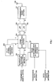
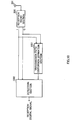
- FIG.1 is a block diagram showing a configuration of a transmission apparatus according to this embodiment.
- the transmission apparatus according to this embodiment mainly consists of frame configuration determination section 101, quadrature baseband modulation section 102, pilot symbol generation section 103, frame configuration section 104, and LPFs(Low Pass Filters)105 and 106, transmission radio section 107 and transmission antenna 108.
- Frame configuration determination section 101 judges the communication situation based on transmission path information which shows the degree of fluctuations of the transmission path due to fading and data transmission speed information which shows the transmission speed of transmission data based on the level of a reception signal and decides the interval of inserting a known pilot symbol and the modulation system of a transmission digital signal. Then, frame configuration determination section 101 outputs a signal indicating the determined modulation system to quadrature baseband modulation section 102 and outputs a signal indicating the determined interval of inserting the known pilot symbol to frame configuration section 104.
- the situation of fluctuations in the transmission path due to fading can be estimated from a transition in the result of measuring the reception level of the modulated signal transmitted from the other end of communication on the receiving side, which is not shown in the figure, of the communication apparatus in which the transmission apparatus shown in FIG.1 is mounted. Furthermore, the transmission apparatus shown in FIG.1 can recognize the situation of fluctuations in the transmission path due to fading, by the reception apparatus, which is the other end of communication of the transmission apparatus shown in FIG.1 , measuring the reception level of the modulated signal transmitted from the other end of communication, estimating the situation of fluctuations in the transmission path due to fading based on the transition of the measurement result.
- the transmission speed of the transmission data can be determined from a result of measuring the reception level of the modulated signal transmitted from the other end of communication on the receiving side, which is not shown in the figure, of the communication apparatus in which the transmission apparatus shown in FIG.1 is mounted. Furthermore, the transmission apparatus shown in FIG.1 can recognize the transmission speed of the transmission data by the reception apparatus, which is the other end of communication of the transmission apparatus shown in FIG.1 , measuring the reception level of the pilot symbol transmitted from the other end of communication and determining the transmission speed of the transmission data based on the measurement result.
- Quadrature baseband modulation section 102 modulates a transmission digital signal to a quadrature baseband signal with the modulation system indicated from frame configuration determination section 101 and outputs the in-phase component and the quadrature component of the quadrature baseband signal to frame configuration section 104.
- Pilot symbol generation section 103 generates a pilot symbol known between the transmitting and receiving sides and outputs the in-phase component and the quadrature component of the known pilot symbol to frame configuration section 104.
- Frame configuration section 104 inserts the known pilot symbol output from pilot symbol generation section 103 into the output signal of quadrature baseband modulation section 102 at the insertion interval instructed from frame configuration determination section 101 and composes a frame.
- LPF 105 lets pass only a predetermined frequency band section of the in-phase component output from frame configuration section 104.
- LPF 106 lets pass only a predetermined frequency band section of the quadrature component output from frame configuration section 104.
- Transmission radio section 107 transmits a radio frequency signal as the electric wave from transmission antenna 108 after performing radio processing on the output signals of LPF 105 and LPF 106.
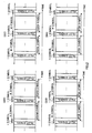
- FIG.2 illustrates examples of a frame configuration of a signal transmitted from the transmission apparatus of this embodiment and shows a time-symbol relationship.
- (201) is a frame configuration when the modulation system of information symbols is 16-value quadrature amplitude modulation (16QAM: 16 Quadrature Amplitude Modulation) and a known pilot symbol interval is N symbols.
- (202) is a frame configuration when the modulation system of information symbols is 16QAM and a known pilot symbol interval is M symbols.
- (203) is a frame configuration when the modulation system of information symbols is 8 phases (8PSK: 8 Phase Shift Keying) modulation and a known pilot symbol interval is N symbols.
- (204) is a frame configuration when the modulation system of information symbols is 8PSK modulation and a known pilot symbol interval is M symbols. Suppose N ⁇ M at this time.
- Frame configuration determination section 101 selects one of (201), (202), (203) or (204) in FIG.2 as the optimal frame configuration based on the transmission path information and the request data transmission speed information.
- frame configuration determination section 101 sacrifices data transmission efficiency on the receiving side and selects a frame configuration of either (201) or (203) in FIG.2 so that the interval of inserting a known pilot symbol becomes narrower to prevent deterioration of the data demodulation error rate and maintain the quality of data.
- frame configuration determination section 101 selects a frame configuration of either (202) or (204) in FIG.2 to widen the interval of inserting a known pilot symbol to improve the data transmission efficiency.
- frame configuration determination section 101 gives priority to data transmission efficiency on the receiving side and selects a frame configuration of either (201) or (202) in FIG. 2 adopting 16QAM as the modulation system of information symbols.
- frame configuration determination section 101 gives priority to increasing error resistance while sacrificing data transmission efficiency on the receiving side and selects a frame configuration of either (203) or (204) in FIG.2 adopting 8PSK as the modulation system of information symbols.
- FIG.3 shows a signal point layout according to the 16QAM modulation system on the in-phase I - quadrature Q plane and signal point layout of a known pilot symbol.
- Signal point 301 is the signal point of a known pilot symbol and signal points 302 are the signal points of 16QAM modulation symbols.
- FIG.4 shows a signal point layout according to the 8PSK modulation system on the in-phase I - quadrature Q plane and signal point layout of a known pilot symbol.
- Signal point 401 is the signal point of a known pilot symbol and signal points 402 are the signal points of 8PSK modulation symbols.
- FIG.5 is a block diagram showing a configuration of the reception apparatus according to this embodiment.
- the reception apparatus according to this Embodiment mainly consists of reception antenna 501, reception radio section 502, transmission path distortion estimation section 503 and detection section 504.
- Reception radio section 502 receives the radio signal received by reception antenna 501 as an input, performs predetermined radio processing and outputs the in-phase component and the quadrature component of the reception quadrature baseband signal.
- Transmission path distortion estimation section 503 receives the in-phase component and the quadrature component of the quadrature baseband signal as inputs, extracts the signal of the known pilot symbol shown in FIG.3 and FIG.4 above, estimates the amount of transmission path distortion from the reception condition of the known pilot symbol and outputs the amount of transmission path distortion to detection section 504.
- Detection section 504 receives the in-phase component and the quadrature component of the quadrature baseband signal as inputs, detects information symbols based on the amount of transmission path distortion and outputs a reception digital signal.
- this embodiment explains two kinds of the interval of inserting a known pilot symbol, but the present invention is not limited to this. Furthermore, this embodiment explains two kinds of the modulation system of information symbols, 16QAM and the 8PSK modulation, but the present invention is not limited to this.
- this embodiment only explains the frame configuration of information symbols and a known pilot symbol shown in FIG. 2 , but since it is also possible to consider a frame configuration in which signals such as a symbol for synchronization to adjust timing between the receiver and transmitter and a symbol to correct an error on the receiver side are inserted, the present invention is not limited to the frame configuration composed of only information symbols and known pilot symbol.
- Example 1 describes a digital radio communication method by which the interval of inserting a BPSK modulation symbol and the modulation system of information symbols other than the above BPSK modulation symbol are changed according to the communication situation.
- FIG. 6 is a block diagram showing a configuration of the transmission apparatus according to this Example.
- the components common to those in the transmission apparatus shown in FIG.1 are assigned the same reference numerals as those in FIG.1 and their explanations will be omitted.
- frame configuration determination section 601 differs in the way of operation from the frame configuration determination section 101 in FIG.1 . Also, when compared to FIG.1 , the transmission apparatus in FIG.6 adopts the configuration with BPSK symbol modulation section 602, instead of pilot symbol generation section 103, added.
- Frame configuration determination section 601 judges the communication situation, determines the interval of inserting a BPSK modulation symbol and the modulation system of a transmission digital signal, outputs a signal indicating the determined modulation system to quadrature baseband modulation section 102 and outputs a signal indicating the interval of inserting the determined BPSK modulation symbol to quadrature baseband modulation section 102, BPSK symbol modulation section 602 and frame configuration section 104.
- BPSK symbol modulation section 602 performs BPSK-modulation on the transmission digital signal at the timing indicated from frame configuration determination section 601 and outputs the in-phase component and the quadrature component of the BPSK modulation symbol to frame configuration section 104.
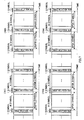
- FIG. 7 illustrates examples of a frame configuration of a signal transmitted from the transmission apparatus of this example and shows a time-symbol relationship.
- (701) is a frame configuration when the modulation system of information symbols is 16QAM and a BPSK modulation symbol interval is N symbols.
- (702) is a frame configuration when the modulation system of information symbols is 16QAM and a BPSK modulation symbol interval is M symbols.
- (703) is a frame configuration when the modulation system of information symbols is 8PSK modulation and a BPSK modulation symbol interval is N symbols.
- (704) is a frame configuration when the modulation system of information symbols is 8PSK modulation and a BPSK modulation symbol interval is M symbols. Suppose N ⁇ M at this time.
- Frame configuration determination section 601 selects one of (701), (702), (703) or (704) in FIG.7 as the optimal frame configuration based on the transmission path information and the request data transmission speed information.
- frame configuration determination section 601 sacrifices data transmission efficiency on the receiving side and selects a frame configuration of either (701) or (703) in FIG.7 so that the interval of inserting a BPSK modulation symbol becomes narrower to prevent deterioration of the data demodulation error rate and maintain the quality of data.
- frame configuration determination section 601 selects a frame configuration of either (702) or (704) in FIG. 7 to widen the interval of inserting a BPSK modulation symbol to improve the data transmission efficiency.
- frame configuration determination section 601 gives priority to data transmission efficiency on the receiving side and selects a frame configuration of either (701) or (702) in the FIG. 7 adopting 16QAM as the modulation system of information symbols.
- frame configuration determination section 601 gives priority to increasing error resistance while sacrificing data transmission efficiency on the receiving side and selects a frame configuration of either (703) or (704) in FIG. 7 adopting 8PSK as the modulation system of information symbols.
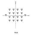
- FIG.8 shows a signal point layout according to the 16QAM modulation system on the in-phase I - quadrature Q plane and signal point layout of BPSK modulation symbols.
- Signal points 801 are the signal points of BPSK modulation symbols and signal points 802 are the signal points of 16QAM modulation symbols.
- FIG.9 shows a signal point layout according to the 8PSK modulation system on the in-phase I - quadrature Q plane and signal point layout of BPSK modulation symbols.
- Signal points 901 are the signal points of BPSK modulation symbols and signal points 902 are the signal points of 8PSK modulation symbols.
- FIG. 10 is a block diagram showing a configuration of the reception apparatus according to this Example.
- the components common to the reception apparatus shown in FIG.5 are assigned the same reference numerals as those in FIG. 5 and their explanations will be omitted.
- transmission path distortion estimation section 1001 differs in the way of operation from transmission path distortion estimation section 503 in FIG.5 and detection section 1002 differs in the way of operation from detection section 504 in FIG.5 .
- Transmission path distortion estimation section 1001 receives the in-phase component and the quadrature component of the quadrature baseband signal as inputs, extracts the signals of the BPSK modulation symbols shown in FIG.8 and FIG.9 above, estimates the amount of transmission path distortion from the reception condition of the BPSK modulation symbols and outputs the amount of transmission path distortion to detection section 1002.
- Detection section 1002 receives the in-phase component and the quadrature component of the quadrature baseband signal as inputs, detects information symbols and BPSK modulation symbols based on the amount of transmission path distortion and outputs a reception digital signal.
- this example describes two kinds of the interval of inserting BPSK modulation symbols but the present invention is not limited to this. Also, this example describes two kinds of the modulation system of information symbols, 16QAM and 8PSK modulation, but the present invention is not limited to this.
- this example describes the frame configuration of only information symbols and BPSK modulation symbols shown in FIG. 7 but the present invention is not limited to this frame configuration.
- Example 2 describes a digital radio communication method by which the interval of inserting QPSK modulation symbols and the modulation system of information symbols other than the above QPSK modulation symbols are changed according to the communication situation.
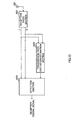
- FIG. 11 is a block diagram showing a configuration of the transmission apparatus according to this Example.
- the components common to those in the transmission apparatus shown in FIG.1 are assigned the same reference numerals as those in FIG.1 and their explanations will be omitted.
- frame configuration determination section 1101 differs in the way of operation from the frame configuration determination section 101 in FIG.1 . Also, when compared to FIG.1 , the transmission apparatus in FIG.11 adopts a configuration with QPSK symbol modulation section 1102, instead of pilot symbol generation section 103, added.
- Frame configuration determination section 1101 judges the communication situation, determines the interval of inserting QPSK modulation symbols and the modulation system of a transmission digital signal, outputs a signal indicating the determined modulation system to quadrature baseband modulation section 102 and outputs a signal indicating the determined interval of inserting QPSK modulation symbols to quadrature baseband modulation section 102, QPSK symbol modulation section 1102 and frame configuration section 104.
- QPSK symbol modulation section 1102 performs QPSK-modulation on a transmission digital signal at the timing indicated from frame configuration determination section 1101 and outputs the in-phase component and the quadrature component of the QPSK modulation symbol to frame configuration section 104.
- FIG.12 illustrates examples of a frame configuration of a signal transmitted from the transmission apparatus of this example and shows a time-symbol relationship.
- (1201) is a frame configuration when the modulation system of information symbols is 16QAM and a QPSK modulation symbol interval is N symbols.
- (1202) is a frame configuration when the modulation system of information symbols is 16QAM and a QPSK modulation symbol interval is M symbols.
- (1203) is a frame configuration when the modulation system of information symbols is 8PSK modulation and a QPSK modulation symbol interval is N symbols.
- (1204) is a frame configuration when the modulation system of information symbols is 8PSK modulation and a QPSK modulation symbol interval is M symbols. Suppose N ⁇ M at this time.
- Frame configuration determination section 1101 selects one of (1201), (1202), (1203) or (1204) in FIG.12 as the optimal frame configuration based on the transmission path information and the request data transmission speed information.
- frame configuration determination section 1101 sacrifices data transmission efficiency on the receiving side and selects a frame configuration of either (1201) or (1203) in FIG.12 so that the QPSK modulation symbol insertion interval becomes narrower to prevent deterioration of the data demodulation error rate and maintain the quality of data.
- frame configuration determination section 1101 selects a frame configuration of either (1202) or (1204) in FIG.12 to widen the interval of inserting QPSK modulation symbols to improve the data transmission efficiency.
- frame configuration determination section 1101 gives priority to data transmission efficiency on the receiving side and selects a frame configuration of either (1201) or (1202) in FIG. 12 adopting 16QAM as the modulation system of information symbols.
- frame configuration determination section 1101 gives priority to increasing error resistance while sacrificing data transmission efficiency on the receiving side and selects a frame configuration of either (1203) or (1204) in FIG.12 adopting 8PSK as the modulation system of information symbols.
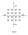
- FIG.13 shows a signal point layout according to the 16QAM modulation system on the in-phase I - quadrature Q plane and signal point layout of QPSK modulation symbols.
- Signal points 1301 are the signal points of QPSK modulation symbols and signal points 1302 are the signal points of 16QAM modulation symbols.
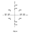
- FIG.14 shows a signal point layout according to the 8PSK modulation system on the in-phase I - quadrature Q plane and signal point layout of QPSK modulation symbols.
- Signal points 1401 are the signal points of QPSK modulation symbols and signal points 1402 are the signal points of 8PSK modulation symbols.
- FIG.15 is a block diagram showing a configuration of the reception apparatus according to example.
- the components common to the reception apparatus shown in FIG.5 are assigned the same reference numerals as those in FIG.5 and their explanations will be omitted.
- transmission path distortion estimation section 1501 differs in the way of operation from transmission path distortion estimation section 503 in FIG.5 and detection section 1502 differs in the way of operation from detection section 504 in FIG.5 .
- Transmission path distortion estimation section 1501 receives the in-phase component and the quadrature component of the quadrature baseband signal as inputs, extracts the signals of the QPSK modulation symbols shown in FIG.13 and FIG.14 above, estimates the amount of transmission path distortion from the reception condition of the QPSK modulation symbols and outputs the amount of transmission path distortion to detection section 1502.
- Detection section 1502 receives the in-phase component and the quadrature component of the quadrature baseband signal as inputs, detects information symbols and QPSK modulation symbols based on the amount of transmission path distortion and outputs a reception digital signal.
- this example describes two kinds of the interval of inserting QPSK modulation symbols but the present invention is not limited to this. Also, this example describes two kinds of the modulation system of information symbols, 16QAM and 8PSK modulation, but the present invention is not limited to this.
- this example describes the frame configuration of only information symbols and QPSK modulation symbols shown in FIG.12 but the present invention is not limited to this frame configuration.
- Embodiment 2 describes a digital radio communication method by which the modulation system of information symbols is changed according to the communication situation and when the modulation system of information symbols uses 8 or more values, a known pilot symbol is inserted with the insertion interval changed according to the communication situation.
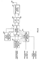
- FIG.16 is a block diagram showing a configuration of the transmission apparatus according to this Embodiment.
- the components common to those in the transmission apparatus shown in FIG.1 are assigned the same reference numerals as those in FIG.1 and their explanations will be omitted.
- frame configuration determination section 1601 differs in the way of operation from the frame configuration determination section 101 in FIG.1 .
- Frame configuration determination section 1601 determines the modulation system of a transmission digital signal based on the communication situation and outputs a signal indicating the determined modulation system to quadrature baseband modulation section 102. Also, when the determined modulation system uses 8 or more values, frame configuration determination section 1601 determines the interval of inserting a pilot symbol based on the communication situation and outputs a signal indicating the determined interval of inserting the pilot symbol to frame configuration section 104. Also, when the determined modulation system uses 8 fewer values, frame configuration determination section 1601 outputs a signal giving an instruction for stopping the generation of pilot symbols to pilot symbol generation section 103.
- Pilot symbol generation section 103 generates a pilot symbol known between the transmitting and receiving sides and outputs the in-phase component and the quadrature component of the known pilot symbol to frame configuration section 104. However, when instructed to stop the generation of pilot symbols from frame configuration determination section 1601, pilot symbol generation section 103 stops operation.
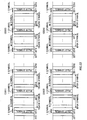
- FIG.17 illustrates examples of a frame configuration of a signal transmitted from the transmission apparatus of this embodiment and shows a time-symbol relationship.
- (1701) is a frame configuration when the modulation system of information symbols is BPSK.
- (1702) is a frame configuration when the modulation system of information symbols is QPSK.
- the ranking of the frame configurations shown in FIG. 2 and FIG.17 in descending order of resistance to fading speed is (1701), (1702), (203), (201), (204) and (202). Furthermore, the ranking in descending order of error resistance is (1701), (1702), (203), (204), (201) and (202). On the other hand, the ranking in descending order of data transmission efficiency on the receiving side is (202), (201), (204), (203), (1702) and (1701).
- Frame configuration determination section 1601 selects one of (201), (202), (203) or (204) in FIG.2 or (1701) or (1702) in FIG. 17 above as the optimal frame configuration based on the transmission path information and the request data transmission speed information.
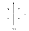
- FIG.18 shows a signal point layout according to the BPSK modulation method on the in-phase I - quadrature Q plane and signal points 1801 are the signal points of BPSK symbols.
- FIG.19 shows a signal point layout according to the QPSK modulation method on the in-phase I - quadrature Q plane and signal points 1901 are the signal points of QPSK symbols.
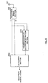
- FIG. 20 is a block diagram showing a configuration of the reception apparatus according to this embodiment.
- the components common to those in the reception apparatus shown in FIG.5 are assigned the same reference numerals as those in FIG.5 and their explanations will be omitted.
- transmission path distortion estimation section 2001 differs in the way of operation from transmission path estimation section 503 in FIG.5 and detection section 2002 differs in the way of operation from detection section 504 in FIG.5 .
- Transmission path distortion estimation section 2001 receives the in-phase component and the quadrature component of the quadrature baseband signal as inputs, estimates the amount of transmission path distortion from the reception condition of the BPSK modulation symbol shown in FIG.18 or the QPSK modulation symbol shown in FIG.19 and outputs the amount of transmission path distortion to detection section 2002.
- Detection section 2002 receives the in-phase component and the quadrature component of the quadrature baseband signal as inputs, detects information symbols based on the amount of transmission path distortion and outputs a reception digital signal.
- the transmission apparatus in FIG.16 can also have a configuration equipped with BPSK symbol modulation section 602 shown in FIG.6 instead of pilot symbol generation section 103.
- frame configuration determination section 1601 determines the modulation system of the transmission digital signal based on the communication situation. For example, frame configuration determination section 1601 selects one of (701), (702), (703) or (704) in FIG.7 above or (1701) or (1702) in FIG.17 as the optimal frame configuration.
- frame configuration determination section 1601 outputs the signals indicating the determined modulation system to quadrature baseband modulation section 102. Also, when the determined modulation system uses 8 or more values, frame configuration determination section 1601 determines the interval of inserting BPSK modulation symbols based on the communication situation and outputs a signal indicating the determined interval of inserting the BPSK modulation symbols to BPSK symbol modulation section 602 and frame configuration section 104. Furthermore, when the determined modulation system is 8 fewer values, frame configuration determination section 1601 outputs a signal giving an instruction for stopping the generation of BPSK modulation symbols to BPSK symbol modulation section 602.
- BPSK symbol modulation section 602 performs BPSK-modulation on a transmission digital signal at the timing indicated from frame configuration determination section 1601 and outputs the in-phase component and the quadrature component of the BPSK modulation symbols to frame configuration section 104. However, when instructed to stop the generation of BPSK modulation symbols from frame configuration determination section 1601, BPSK symbol modulation section 602 stops operation.
- Transmission path distortion estimation section 2001 receives the in-phase component and the quadrature component of the quadrature baseband signal as inputs, estimates the amount of transmission path distortion from the reception condition of the BPSK modulation symbols shown in FIG.8 and FIG.9 above, the BPSK modulation symbols shown in FIG.18 or the QPSK modulation symbols shown in FIG.19 and outputs the amount of transmission path distortion to detection section 2002.
- the transmission apparatus in FIG.16 can also have a configuration equipped with QPSK symbol modulation section 1102 shown in FIG.11 instead of pilot symbol generation section 103.
- frame configuration determination section 1601 determines the modulation system of the transmission digital signal based on the communication situation. For example, frame configuration determination section 1601 selects one of (1201), (1202), (1203) or (1204) in FIG.12 above or (1701) or (1702) in FIG.17 as the optimal frame configuration.
- frame configuration determination section 1601 outputs a signal indicating the determined modulation system to quadrature baseband modulation section 102. Also, when the determined modulation system uses 8 or more values, frame configuration determination section 1601 determines the interval of inserting QPSK modulation symbols based on the communication situation and outputs a signal indicating the determined interval of inserting the QPSK symbols to QPSK symbol modulation section 1102 and frame configuration section 104. Also, when the determined modulation system is 8 fewer values, frame configuration determination section 1601 outputs a signal giving an instruction for stopping the generation of QPSK modulation symbols to QPSK symbol modulation section 1102.
- QPSK symbol modulation section 1102 performs QPSK-modulation on a transmission digital signal at the timing indicated from frame configuration determination section 1601 and outputs the in-phase component and the quadrature component of the QPSK modulation symbols to frame configuration section 104. However, when instructed to stop generating QPSK modulation symbols from frame configuration determination section 1601, QPSK symbol modulation section 1102 stops operation.
- Transmission path distortion estimation section 2001 receives the in-phase component and the quadrature component of the quadrature baseband signal as inputs, estimates the amount of transmission path distortion from the reception condition of the QPSK modulation symbols shown in FIG.13 or FIG.14 and the BPSK modulation symbols shown in FIG.18 or the QPSK modulation symbol shown in FIG.19 and outputs the amount of transmission path distortion to detection section 2002.
- this embodiment explains two kinds of the interval of inserting a known pilot symbol, but the present invention is not limited to this. Also, this embodiment explains two kinds of the multi-value modulation system with 8 or more values of information symbols, 16QAM and the 8PSK modulation, but the present invention is not limited to this.
- this embodiment describes the frame configurations in FIG. 2 , FIG. 7 , FIG.12 and FIG.17 but the present invention is not limited to these frame configurations.
- the BPSK modulation method and the QPSK modulation method of the modulation system of information symbols of the present invention are not limited to the signal point layouts shown in FIG.18 and FIG.19 but ⁇ /2 shift BPSK modulation or ⁇ /4 shift QPSK modulation can also be used.
- Embodiment 3 describes a digital radio communication method by which the interval of inserting a known pilot symbol, the number of signal points with one symbol immediately before and after a known pilot symbol (hereinafter referred to as "symbols before and after a pilot") and signal point layout and the modulation system of information symbols other than those symbols are changed.
- FIG.21 is a block diagram showing a configuration of the transmission apparatus according to this embodiment.
- the components common to those in the transmission apparatus shown in FIG.1 are assigned the same reference numerals as those shown in FIG.1 and their explanations will be omitted.
- frame configuration determination section 2101 differs in the way of operation from frame configuration determination section 101 in FIG.1 . Furthermore, the transmission apparatus in FIG.21 adopts a configuration with symbols before and after a pilot modulation section 2102 added compared to FIG.1 .
- Frame configuration determination section 2101 determines the interval of inserting a known pilot symbol and the modulation system of a transmission digital signal based on the communication situation. In this case, frame configuration determination section 2101 uses different modulation systems for symbols before and after a pilot and for other information symbols.
- frame configuration determination section 2101 outputs a signal indicating the modulation system of symbols before and after a pilot to symbols before and after a pilot modulation section 2102, outputs a signal indicating the modulation system of other information symbols to quadrature baseband modulation section 102 and outputs a signal indicating the interval of inserting the determined known pilot symbol to symbols before and after a pilot modulation section 2102 and frame configuration section 104.
- Symbols before and after a pilot modulation section 2102 modulates on a transmission digital signal by predetermined modulation system at the timing indicated from frame configuration determination section 2101 and outputs the in-phase component and the quadrature component of the symbols before and after a pilot to frame configuration section 104.
- FIG.22 illustrates examples of a frame configuration of a signal transmitted from the transmission apparatus of this embodiment and shows a time-symbol relationship.
- (2201) is a frame configuration when the modulation system of information symbols is 16QAM and a known pilot symbol interval is N symbols.
- (2202) is a frame configuration when the modulation system of information symbols is 16QAM and a known pilot symbol interval is M symbols.
- (2203) is a frame configuration when the modulation system of information symbols is 8PSK modulation and a known pilot symbol interval is N symbols.
- (2204) is a frame configuration when the modulation system of information symbols is 8PSK modulation and a known pilot symbol interval is M symbols. Suppose N ⁇ M at this time.
- Signal point 2211 is 1 symbol immediately before the known pilot symbol when the information symbol modulation system is 16QAM and signal point 2212 is 1 symbol immediately after the known pilot symbol when the information symbol modulation system is 16QAM.
- Signal point 2213 is 1 symbol immediately before the known pilot symbol when the information symbol modulation system is 8PSK modulation and signal point 2214 is 1 symbol immediately after the known pilot symbol when the information symbol modulation system is 8PSK modulation.
- Frame configuration determination section 2101 selects one of (2201), (2202), (2203) or (2204) in FIG. 22 as the optimal frame configuration based on the transmission path information and the request data transmission speed information.
- frame configuration determination section 2101 sacrifices data transmission efficiency on the receiving side and selects a frame configuration of either (2201) or (2203) in FIG.22 so that the interval of inserting a known pilot symbol becomes narrower to prevent deterioration of the data demodulation error rate and maintain the quality of data.
- frame configuration determination section 2101 selects a frame configuration of either (2202) or (2204) in FIG. 22 to widen the interval of inserting a known pilot symbol to improve the data transmission efficiency.
- frame configuration determination section 2101 gives priority to data transmission efficiency on the receiving side and selects a frame configuration of either (2201) or (2202) in FIG. 22 adopting 16QAM as the modulation system of information symbols.
- frame configuration determination section 2101 gives priority to increasing error resistance while sacrificing data transmission efficiency on the receiving side and selects a frame configuration of either (2203) or (2204) in FIG.22 adopting 8PSK as the modulation system of information symbols.
- FIG. 23 shows a signal point layout according to the 16QAM modulation method on the in-phase I - quadrature Q plane and a signal point layout according to a known pilot symbol and a signal point layout of symbols before and after a pilot.
- Signal point 2301 is the signal point of a known pilot symbol
- signal points 2302 are the signal points of 16QAM modulation symbols
- signal points 2303 are the signal points of symbols before and after a pilot.
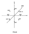
- FIG.24 shows a signal point layout according to the 8PSK modulation system on the in-phase I - quadrature Q plane, a signal point layout of a known pilot symbol and a signal point layout of symbols before and after a pilot.
- Signal points 2401, 2401-A and 2401-B are the signal points of 8PSK modulation symbols
- 2401-A is the signal point of the known pilot symbol
- 2401-A and 2401-B are the signal points of symbols before and after a pilot
- straight line 2402 is the straight line formed by linking the signal point of the known pilot symbol and the origin on the in-phase I - quadrature Q plane.
- FIG. 25 is a block diagram showing a configuration of the reception apparatus according to this embodiment.
- the components common to those in the reception apparatus shown in FIG.5 are assigned the same reference numerals as those shown in FIG.5 and their explanations will be omitted.
- transmission path estimation section 2501 differs in the way of operation from transmission path estimation section 503 and detection section 2502 differs in the way of operation from detection section 504 in FIG.5 .
- Transmission path distortion estimation section 2501 receives the in-phase component and the quadrature component of the quadrature baseband signal as inputs, extracts the signal of the known pilot symbol shown in FIG.23 and FIG.24 above, estimates the amount of transmission path distortion from the reception condition of the known pilot symbol and outputs the amount of transmission path distortion to detection section 2502.
- Detection section 2502 receives the in-phase component and the quadrature component of the quadrature baseband signal as inputs, detects information symbols including symbols before and after a pilot based on the amount of transmission path distortion and outputs a reception digital signal.
- frame configuration determination section 2101 in FIG.21 determines the interval of inserting a pilot symbol based on the communication situation and outputs a signal indicating the interval of inserting the determined pilot symbol to symbols before and after a pilot modulation section 2102 and frame configuration section 104. Furthermore, when the determined modulation system uses 8 fewer values, frame configuration determination section 2101 outputs a signal giving an instruction for stopping the generation of pilot symbols to symbols before and after a pilot modulation section 2102 and pilot symbol generation section 103.
- Pilot symbol generation section 103 generates a pilot symbol known between the transmitting and receiving sides and outputs the in-phase component and the quadrature component of the known pilot symbol to frame configuration section 104. However, when instructed to stop the generation of pilot symbols from frame configuration determination section 2101, pilot symbol generation section 103 stops operation.
- Symbols before and after a pilot modulation section 2102 performs BPSK-modulation or QPSK-modulation on a transmission digital signal at the timing indicated from frame configuration determination section 2101 and outputs the in-phase component and the quadrature component of the symbols before and after a pilot to frame configuration section 104. However, when instructed to stop the generation of pilot symbols from frame configuration determination section 2101, symbols before and after a pilot modulation section 2102 stops operation.
- this embodiment describes two kinds of modulation system of information symbols, 16QAM and 8PSK modulation, but the present invention is not limited to this.
- this embodiment explains only the configuration of information symbols, a known pilot symbol, symbols before and after a pilot in FIG.22 , but the frame configuration of the present invention is not limited to the frameA configuration composed of only information symbols, a known pilot symbol, symbols before and after a pilot.
- the present invention by changing the interval of inserting a known pilot symbol, BPSK modulation symbols or QPSK modulation symbols and the modulation system of information symbols according to the communication situation of fluctuations in the transmission path and the level of the reception signal, etc., it is possible to improve both the data transmission efficiency and the quality of data at the same time.
Description
- The present invention relates to a transmission apparatus, reception apparatus and digital radio communication method, which is used for digital radio communications.
- As a conventional digital modulation system, a technology described in the Unexamined Japanese Patent Publication No.
HEI 1-196924 - Here, in the case of a radio communication, fluctuations in the transmission path occur due to fading and in terrestrial mobile communication in particular, fluctuations in the transmission path are not uniform. When fluctuations in the transmission path are intense, the interval of inserting a pilot symbol must be shorter to prevent deterioration of the data demodulation error rate. On the contrary, when fluctuations in the transmission path are gentle, extending the interval of inserting a pilot symbol does not deteriorate the data demodulation error rate so much.
- On the other hand, when the level of a reception signal on the receiving side is small, a modulation system used must be highly resistant to errors for information symbols. On the contrary, when the level of a reception signal on the receiving side is large, higher priority can be given to a modulation system of high transmission efficiency for information symbols.
- However, in the conventional digital modulation system above, the pilot symbol insertion interval and the information symbol modulation system are fixed. Therefore, when fluctuations in the transmission path are intense or the level of the reception signal of the receiver is small, error resistance during data demodulation reduces and the quality of data deteriorates. On the other hand, when fluctuations in the transmission path are gentle or the level of the reception signal on the receiving side is large, the data transmission efficiency cannot be improved despite the excessive data quality.
- The European patent application
EP 0 734 132 A2 discloses a signal structure for multicarrier modulation, in which reference symbols are placed in the beginning portion of the frame and data symbols are placed in an information symbol data region in the frame with equal spacings in time and frequency. At the receiving end of the disclosed transmission system, an error detector detects amplitude and phase errors of each carrier from the reference symbols, and the amplitude and phase errors of the received data signals are corrected via correction section. - It is an object of the present invention to provide a transmission apparatus, reception apparatus and digital radio communication method capable of flexibly improving the data transmission efficiency and the quality of data.
- The present invention attains the above object by employing an apparatus and a method claimed in the present claims.
- The above and other objects and features of the invention will appear more fully hereinafter from a consideration of the following description taken in connection with the accompanying drawing wherein one example is illustrated by way of example, in which;
-
FIG.1 is a block diagram showing a configuration of a transmission apparatus according toEmbodiment 1 of the present invention; -
FIG.2 illustrates examples of a frame configuration of a signal transmitted from the transmission apparatus ofEmbodiment 1 of the present invention; -
FIG.3 is a layout of signal points of 16QAM and a known pilot symbol on an in-phase I - quadrature Q plane; -
FIG.4 is a layout of signal points of 8PSK modulation and a known pilot symbol on an in-phase I - quadrature Q plane; -
FIG.5 is a block diagram showing a configuration of a reception apparatus according toEmbodiment 1 of the present invention; -
FIG.6 is a block diagram showing a configuration of a transmission apparatus according to example 1 of the present invention; -
FIG.7 illustrates examples of a frame configuration of a signal transmitted from the transmission apparatus of Example 1 of the present invention; -
FIG.8 is a layout of signal points of 16QAM and BPSK modulation on an in-phase I - quadrature Q plane; -
FIG.9 is a layout of signal points of 8PSK modulation and BPSK modulation on an in-phase I - quadrature Q plane; -
FIG.10 is a block diagram showing a configuration of a reception apparatus according to Example 1 of the present invention; -
FIG.11 is a block diagram showing a configuration of a transmission apparatus according to Example 2 of the present invention; -
FIG.12 illustrates examples of a frame configuration of a signal transmitted from the transmission apparatus of Example 2 of the present invention; -
FIG.13 is a layout of signal points of 16QAM and QPSK modulation on an in-phase I - quadrature Q plane; -
FIG.14 is a layout of signal points of 8PSK modulation and QPSK modulation on an in-phase I - quadrature Q plane; -
FIG.15 is a block diagram showing a configuration of a reception apparatus according to Example 2 of the present invention; -
FIG.16 is a block diagram showing a configuration of a transmission apparatus according to Embodiment 2 of the present invention; -
FIG.17 illustrates examples of a frame configuration of a signal transmitted from the transmission apparatus of Embodiment 2 of the present invention; -
FIG.18 is a layout of signal points of BPSK modulation on an in-phase I - quadrature Q plane; -
FIG.19 is a layout of signal points of QPSK modulation on an in-phase I - quadrature Q plane; -
FIG.20 is a block diagram showing a configuration of a reception apparatus according to Embodiment 2 of the present invention; -
FIG.21 is a block diagram showing a configuration of a transmission apparatus according to Embodiment 3 of the present invention; -
FIG.22 illustrates examples of a frame configuration of a signal transmitted from the transmission apparatus of the Embodiment 3 of the present invention; -
FIG.23 is a layout of signal points of 16QAM, a known pilot symbol and symbols before and after the pilot symbol on an in-phase I - quadrature Q plane; -
FIG.24 is a layout of signal points of 8PSK modulation, a known pilot symbol and symbols before and after the pilot symbol on an in-phase I - quadrature Q plane; and -
FIG.25 is a block diagram showing a configuration of a reception apparatus according to Embodiment 3 of the present invention. - With reference now to the attached drawings, embodiments of the present invention will be explained in detail below.
-
Embodiment 1 describes a digital radio communication method by which the interval of inserting a known pilot symbol and the modulation system of information symbols are changed according to the communication situation. -
FIG.1 is a block diagram showing a configuration of a transmission apparatus according to this embodiment. As shown inFIG.1 , the transmission apparatus according to this embodiment mainly consists of frameconfiguration determination section 101, quadraturebaseband modulation section 102, pilotsymbol generation section 103,frame configuration section 104, and LPFs(Low Pass Filters)105 and 106,transmission radio section 107 andtransmission antenna 108. - Frame
configuration determination section 101 judges the communication situation based on transmission path information which shows the degree of fluctuations of the transmission path due to fading and data transmission speed information which shows the transmission speed of transmission data based on the level of a reception signal and decides the interval of inserting a known pilot symbol and the modulation system of a transmission digital signal. Then, frameconfiguration determination section 101 outputs a signal indicating the determined modulation system to quadraturebaseband modulation section 102 and outputs a signal indicating the determined interval of inserting the known pilot symbol toframe configuration section 104. By the way, details of the method of determining a frame configuration by frameconfiguration determination section 101 will be described later. - Here, when an identical frequency band is used for the uplink and the downlink, the situation of fluctuations in the transmission path due to fading can be estimated from a transition in the result of measuring the reception level of the modulated signal transmitted from the other end of communication on the receiving side, which is not shown in the figure, of the communication apparatus in which the transmission apparatus shown in
FIG.1 is mounted. Furthermore, the transmission apparatus shown inFIG.1 can recognize the situation of fluctuations in the transmission path due to fading, by the reception apparatus, which is the other end of communication of the transmission apparatus shown inFIG.1 , measuring the reception level of the modulated signal transmitted from the other end of communication, estimating the situation of fluctuations in the transmission path due to fading based on the transition of the measurement result. - Then, when an identical frequency band is used for the uplink and the downlink, the transmission speed of the transmission data can be determined from a result of measuring the reception level of the modulated signal transmitted from the other end of communication on the receiving side, which is not shown in the figure, of the communication apparatus in which the transmission apparatus shown in
FIG.1 is mounted. Furthermore, the transmission apparatus shown inFIG.1 can recognize the transmission speed of the transmission data by the reception apparatus, which is the other end of communication of the transmission apparatus shown inFIG.1 , measuring the reception level of the pilot symbol transmitted from the other end of communication and determining the transmission speed of the transmission data based on the measurement result. - Quadrature
baseband modulation section 102 modulates a transmission digital signal to a quadrature baseband signal with the modulation system indicated from frameconfiguration determination section 101 and outputs the in-phase component and the quadrature component of the quadrature baseband signal toframe configuration section 104. - Pilot
symbol generation section 103 generates a pilot symbol known between the transmitting and receiving sides and outputs the in-phase component and the quadrature component of the known pilot symbol toframe configuration section 104. -
Frame configuration section 104 inserts the known pilot symbol output from pilotsymbol generation section 103 into the output signal of quadraturebaseband modulation section 102 at the insertion interval instructed from frameconfiguration determination section 101 and composes a frame. -
LPF 105 lets pass only a predetermined frequency band section of the in-phase component output fromframe configuration section 104.LPF 106 lets pass only a predetermined frequency band section of the quadrature component output fromframe configuration section 104. -
Transmission radio section 107 transmits a radio frequency signal as the electric wave fromtransmission antenna 108 after performing radio processing on the output signals ofLPF 105 andLPF 106. - Next, examples of the method of determining a frame configuration by frame
configuration determination section 101 of the transmission apparatus shown inFIG.1 above will be explained. -
FIG.2 illustrates examples of a frame configuration of a signal transmitted from the transmission apparatus of this embodiment and shows a time-symbol relationship. (201) is a frame configuration when the modulation system of information symbols is 16-value quadrature amplitude modulation (16QAM: 16 Quadrature Amplitude Modulation) and a known pilot symbol interval is N symbols. (202) is a frame configuration when the modulation system of information symbols is 16QAM and a known pilot symbol interval is M symbols. (203) is a frame configuration when the modulation system of information symbols is 8 phases (8PSK: 8 Phase Shift Keying) modulation and a known pilot symbol interval is N symbols. (204) is a frame configuration when the modulation system of information symbols is 8PSK modulation and a known pilot symbol interval is M symbols. Suppose N<M at this time. - Frame
configuration determination section 101 selects one of (201), (202), (203) or (204) inFIG.2 as the optimal frame configuration based on the transmission path information and the request data transmission speed information. - For example, in the case of high-speed fading, frame
configuration determination section 101 sacrifices data transmission efficiency on the receiving side and selects a frame configuration of either (201) or (203) inFIG.2 so that the interval of inserting a known pilot symbol becomes narrower to prevent deterioration of the data demodulation error rate and maintain the quality of data. On the other hand, in the case of low-speed fading, frameconfiguration determination section 101 selects a frame configuration of either (202) or (204) inFIG.2 to widen the interval of inserting a known pilot symbol to improve the data transmission efficiency. - Also, when the level of the reception signal is large, frame
configuration determination section 101 gives priority to data transmission efficiency on the receiving side and selects a frame configuration of either (201) or (202) inFIG. 2 adopting 16QAM as the modulation system of information symbols. On the other hand, when the level of the reception signal is small, frameconfiguration determination section 101 gives priority to increasing error resistance while sacrificing data transmission efficiency on the receiving side and selects a frame configuration of either (203) or (204) inFIG.2 adopting 8PSK as the modulation system of information symbols. -
FIG.3 shows a signal point layout according to the 16QAM modulation system on the in-phase I - quadrature Q plane and signal point layout of a known pilot symbol.Signal point 301 is the signal point of a known pilot symbol and signalpoints 302 are the signal points of 16QAM modulation symbols.FIG.4 shows a signal point layout according to the 8PSK modulation system on the in-phase I - quadrature Q plane and signal point layout of a known pilot symbol.Signal point 401 is the signal point of a known pilot symbol and signalpoints 402 are the signal points of 8PSK modulation symbols. -
FIG.5 is a block diagram showing a configuration of the reception apparatus according to this embodiment. As shown inFIG.5 , the reception apparatus according to this Embodiment mainly consists ofreception antenna 501,reception radio section 502, transmission pathdistortion estimation section 503 anddetection section 504. -
Reception radio section 502 receives the radio signal received byreception antenna 501 as an input, performs predetermined radio processing and outputs the in-phase component and the quadrature component of the reception quadrature baseband signal. - Transmission path
distortion estimation section 503 receives the in-phase component and the quadrature component of the quadrature baseband signal as inputs, extracts the signal of the known pilot symbol shown inFIG.3 andFIG.4 above, estimates the amount of transmission path distortion from the reception condition of the known pilot symbol and outputs the amount of transmission path distortion todetection section 504. -
Detection section 504 receives the in-phase component and the quadrature component of the quadrature baseband signal as inputs, detects information symbols based on the amount of transmission path distortion and outputs a reception digital signal. - Thus, changing the interval of inserting a known pilot symbol and the modulation system of information symbols according to the communication situation such as fluctuations in the transmission path and the level of the reception signal can improve both the data transmission efficiency and the quality of data at the same time.
- Here, this embodiment explains two kinds of the interval of inserting a known pilot symbol, but the present invention is not limited to this. Furthermore, this embodiment explains two kinds of the modulation system of information symbols, 16QAM and the 8PSK modulation, but the present invention is not limited to this.
- Furthermore, this embodiment only explains the frame configuration of information symbols and a known pilot symbol shown in
FIG. 2 , but since it is also possible to consider a frame configuration in which signals such as a symbol for synchronization to adjust timing between the receiver and transmitter and a symbol to correct an error on the receiver side are inserted, the present invention is not limited to the frame configuration composed of only information symbols and known pilot symbol. - Example 1 describes a digital radio communication method by which the interval of inserting a BPSK modulation symbol and the modulation system of information symbols other than the above BPSK modulation symbol are changed according to the communication situation.
-
FIG. 6 is a block diagram showing a configuration of the transmission apparatus according to this Example. Here, in the transmission apparatus shown inFIG. 6 , the components common to those in the transmission apparatus shown inFIG.1 are assigned the same reference numerals as those inFIG.1 and their explanations will be omitted. - In the transmission apparatus in
FIG.6 , frameconfiguration determination section 601 differs in the way of operation from the frameconfiguration determination section 101 inFIG.1 . Also, when compared toFIG.1 , the transmission apparatus inFIG.6 adopts the configuration with BPSKsymbol modulation section 602, instead of pilotsymbol generation section 103, added. - Frame
configuration determination section 601 judges the communication situation, determines the interval of inserting a BPSK modulation symbol and the modulation system of a transmission digital signal, outputs a signal indicating the determined modulation system to quadraturebaseband modulation section 102 and outputs a signal indicating the interval of inserting the determined BPSK modulation symbol to quadraturebaseband modulation section 102, BPSKsymbol modulation section 602 andframe configuration section 104. - BPSK
symbol modulation section 602 performs BPSK-modulation on the transmission digital signal at the timing indicated from frameconfiguration determination section 601 and outputs the in-phase component and the quadrature component of the BPSK modulation symbol to frameconfiguration section 104. -
FIG. 7 illustrates examples of a frame configuration of a signal transmitted from the transmission apparatus of this example and shows a time-symbol relationship. (701) is a frame configuration when the modulation system of information symbols is 16QAM and a BPSK modulation symbol interval is N symbols. (702) is a frame configuration when the modulation system of information symbols is 16QAM and a BPSK modulation symbol interval is M symbols. (703) is a frame configuration when the modulation system of information symbols is 8PSK modulation and a BPSK modulation symbol interval is N symbols. (704) is a frame configuration when the modulation system of information symbols is 8PSK modulation and a BPSK modulation symbol interval is M symbols. Suppose N<M at this time. - Frame
configuration determination section 601 selects one of (701), (702), (703) or (704) inFIG.7 as the optimal frame configuration based on the transmission path information and the request data transmission speed information. - For example, in the case of high-speed fading, frame
configuration determination section 601 sacrifices data transmission efficiency on the receiving side and selects a frame configuration of either (701) or (703) inFIG.7 so that the interval of inserting a BPSK modulation symbol becomes narrower to prevent deterioration of the data demodulation error rate and maintain the quality of data. On the other hand, in the case of low-speed fading, frameconfiguration determination section 601 selects a frame configuration of either (702) or (704) inFIG. 7 to widen the interval of inserting a BPSK modulation symbol to improve the data transmission efficiency. - Furthermore, when the level of the reception signal is large, frame
configuration determination section 601 gives priority to data transmission efficiency on the receiving side and selects a frame configuration of either (701) or (702) in theFIG. 7 adopting 16QAM as the modulation system of information symbols. On the other hand, when the level of the reception signal is small, frameconfiguration determination section 601 gives priority to increasing error resistance while sacrificing data transmission efficiency on the receiving side and selects a frame configuration of either (703) or (704) inFIG. 7 adopting 8PSK as the modulation system of information symbols. -
FIG.8 shows a signal point layout according to the 16QAM modulation system on the in-phase I - quadrature Q plane and signal point layout of BPSK modulation symbols. Signal points 801 are the signal points of BPSK modulation symbols and signalpoints 802 are the signal points of 16QAM modulation symbols.FIG.9 shows a signal point layout according to the 8PSK modulation system on the in-phase I - quadrature Q plane and signal point layout of BPSK modulation symbols. Signal points 901 are the signal points of BPSK modulation symbols and signalpoints 902 are the signal points of 8PSK modulation symbols. -
FIG. 10 is a block diagram showing a configuration of the reception apparatus according to this Example. In the reception apparatus shown inFIG. 10 , the components common to the reception apparatus shown inFIG.5 are assigned the same reference numerals as those inFIG. 5 and their explanations will be omitted. - In the reception apparatus in
FIG.10 , transmission pathdistortion estimation section 1001 differs in the way of operation from transmission pathdistortion estimation section 503 inFIG.5 anddetection section 1002 differs in the way of operation fromdetection section 504 inFIG.5 . - Transmission path
distortion estimation section 1001 receives the in-phase component and the quadrature component of the quadrature baseband signal as inputs, extracts the signals of the BPSK modulation symbols shown inFIG.8 andFIG.9 above, estimates the amount of transmission path distortion from the reception condition of the BPSK modulation symbols and outputs the amount of transmission path distortion todetection section 1002. -
Detection section 1002 receives the in-phase component and the quadrature component of the quadrature baseband signal as inputs, detects information symbols and BPSK modulation symbols based on the amount of transmission path distortion and outputs a reception digital signal. - Thus, in this example, by sending information with BPSK modulation symbols, instead of a known pilot symbol, inserted, it is possible to improve the transmission speed compared with
Embodiment 1. - Here, this example describes two kinds of the interval of inserting BPSK modulation symbols but the present invention is not limited to this. Also, this example describes two kinds of the modulation system of information symbols, 16QAM and 8PSK modulation, but the present invention is not limited to this.
- Furthermore, this example describes the frame configuration of only information symbols and BPSK modulation symbols shown in
FIG. 7 but the present invention is not limited to this frame configuration. - Example 2 describes a digital radio communication method by which the interval of inserting QPSK modulation symbols and the modulation system of information symbols other than the above QPSK modulation symbols are changed according to the communication situation.
-
FIG. 11 is a block diagram showing a configuration of the transmission apparatus according to this Example. In the transmission apparatus shown inFIG.11 , the components common to those in the transmission apparatus shown inFIG.1 are assigned the same reference numerals as those inFIG.1 and their explanations will be omitted. - In the transmission apparatus in
FIG.11 , frameconfiguration determination section 1101 differs in the way of operation from the frameconfiguration determination section 101 inFIG.1 . Also, when compared toFIG.1 , the transmission apparatus inFIG.11 adopts a configuration with QPSKsymbol modulation section 1102, instead of pilotsymbol generation section 103, added. - Frame
configuration determination section 1101 judges the communication situation, determines the interval of inserting QPSK modulation symbols and the modulation system of a transmission digital signal, outputs a signal indicating the determined modulation system to quadraturebaseband modulation section 102 and outputs a signal indicating the determined interval of inserting QPSK modulation symbols to quadraturebaseband modulation section 102, QPSKsymbol modulation section 1102 andframe configuration section 104. - QPSK
symbol modulation section 1102 performs QPSK-modulation on a transmission digital signal at the timing indicated from frameconfiguration determination section 1101 and outputs the in-phase component and the quadrature component of the QPSK modulation symbol to frameconfiguration section 104. -
FIG.12 illustrates examples of a frame configuration of a signal transmitted from the transmission apparatus of this example and shows a time-symbol relationship. (1201) is a frame configuration when the modulation system of information symbols is 16QAM and a QPSK modulation symbol interval is N symbols. (1202) is a frame configuration when the modulation system of information symbols is 16QAM and a QPSK modulation symbol interval is M symbols. (1203) is a frame configuration when the modulation system of information symbols is 8PSK modulation and a QPSK modulation symbol interval is N symbols. (1204) is a frame configuration when the modulation system of information symbols is 8PSK modulation and a QPSK modulation symbol interval is M symbols. Suppose N<M at this time. - Frame
configuration determination section 1101 selects one of (1201), (1202), (1203) or (1204) inFIG.12 as the optimal frame configuration based on the transmission path information and the request data transmission speed information. - For example, in the case of high-speed fading, frame
configuration determination section 1101 sacrifices data transmission efficiency on the receiving side and selects a frame configuration of either (1201) or (1203) inFIG.12 so that the QPSK modulation symbol insertion interval becomes narrower to prevent deterioration of the data demodulation error rate and maintain the quality of data. On the other hand, in the case of low-speed fading, frameconfiguration determination section 1101 selects a frame configuration of either (1202) or (1204) inFIG.12 to widen the interval of inserting QPSK modulation symbols to improve the data transmission efficiency. - Furthermore, when the level of the reception signal is large, frame
configuration determination section 1101 gives priority to data transmission efficiency on the receiving side and selects a frame configuration of either (1201) or (1202) inFIG. 12 adopting 16QAM as the modulation system of information symbols. On the other hand, when the level of the reception signal is small, frameconfiguration determination section 1101 gives priority to increasing error resistance while sacrificing data transmission efficiency on the receiving side and selects a frame configuration of either (1203) or (1204) inFIG.12 adopting 8PSK as the modulation system of information symbols. -
FIG.13 shows a signal point layout according to the 16QAM modulation system on the in-phase I - quadrature Q plane and signal point layout of QPSK modulation symbols. Signal points 1301 are the signal points of QPSK modulation symbols andsignal points 1302 are the signal points of 16QAM modulation symbols.FIG.14 shows a signal point layout according to the 8PSK modulation system on the in-phase I - quadrature Q plane and signal point layout of QPSK modulation symbols. Signal points 1401 are the signal points of QPSK modulation symbols andsignal points 1402 are the signal points of 8PSK modulation symbols. -
FIG.15 is a block diagram showing a configuration of the reception apparatus according to example. In the reception apparatus shown inFIG.15 , the components common to the reception apparatus shown inFIG.5 are assigned the same reference numerals as those inFIG.5 and their explanations will be omitted. - In the reception apparatus in
FIG.15 , transmission pathdistortion estimation section 1501 differs in the way of operation from transmission pathdistortion estimation section 503 inFIG.5 anddetection section 1502 differs in the way of operation fromdetection section 504 inFIG.5 . - Transmission path
distortion estimation section 1501 receives the in-phase component and the quadrature component of the quadrature baseband signal as inputs, extracts the signals of the QPSK modulation symbols shown inFIG.13 andFIG.14 above, estimates the amount of transmission path distortion from the reception condition of the QPSK modulation symbols and outputs the amount of transmission path distortion todetection section 1502. -
Detection section 1502 receives the in-phase component and the quadrature component of the quadrature baseband signal as inputs, detects information symbols and QPSK modulation symbols based on the amount of transmission path distortion and outputs a reception digital signal. - Thus, in this example, by sending information with QPSK modulation symbols, instead of a known pilot symbol, inserted, it is possible to improve the transmission speed compared with
Embodiment 1 and Example 1. - Here, this example describes two kinds of the interval of inserting QPSK modulation symbols but the present invention is not limited to this. Also, this example describes two kinds of the modulation system of information symbols, 16QAM and 8PSK modulation, but the present invention is not limited to this.
- Furthermore, this example describes the frame configuration of only information symbols and QPSK modulation symbols shown in
FIG.12 but the present invention is not limited to this frame configuration. - Embodiment 2 describes a digital radio communication method by which the modulation system of information symbols is changed according to the communication situation and when the modulation system of information symbols uses 8 or more values, a known pilot symbol is inserted with the insertion interval changed according to the communication situation.
-
FIG.16 is a block diagram showing a configuration of the transmission apparatus according to this Embodiment. In the transmission apparatus shown inFIG.16 , the components common to those in the transmission apparatus shown inFIG.1 are assigned the same reference numerals as those inFIG.1 and their explanations will be omitted. - In the transmission apparatus in
FIG.16 , frameconfiguration determination section 1601 differs in the way of operation from the frameconfiguration determination section 101 inFIG.1 . - Frame
configuration determination section 1601 determines the modulation system of a transmission digital signal based on the communication situation and outputs a signal indicating the determined modulation system to quadraturebaseband modulation section 102. Also, when the determined modulation system uses 8 or more values, frameconfiguration determination section 1601 determines the interval of inserting a pilot symbol based on the communication situation and outputs a signal indicating the determined interval of inserting the pilot symbol to frameconfiguration section 104. Also, when the determined modulation system uses 8 fewer values, frameconfiguration determination section 1601 outputs a signal giving an instruction for stopping the generation of pilot symbols to pilotsymbol generation section 103. - Pilot
symbol generation section 103 generates a pilot symbol known between the transmitting and receiving sides and outputs the in-phase component and the quadrature component of the known pilot symbol to frameconfiguration section 104. However, when instructed to stop the generation of pilot symbols from frameconfiguration determination section 1601, pilotsymbol generation section 103 stops operation. -
FIG.17 illustrates examples of a frame configuration of a signal transmitted from the transmission apparatus of this embodiment and shows a time-symbol relationship. (1701) is a frame configuration when the modulation system of information symbols is BPSK. (1702) is a frame configuration when the modulation system of information symbols is QPSK. - The ranking of the frame configurations shown in
FIG. 2 andFIG.17 in descending order of resistance to fading speed is (1701), (1702), (203), (201), (204) and (202). Furthermore, the ranking in descending order of error resistance is (1701), (1702), (203), (204), (201) and (202). On the other hand, the ranking in descending order of data transmission efficiency on the receiving side is (202), (201), (204), (203), (1702) and (1701). - Frame
configuration determination section 1601 selects one of (201), (202), (203) or (204) inFIG.2 or (1701) or (1702) inFIG. 17 above as the optimal frame configuration based on the transmission path information and the request data transmission speed information. -
FIG.18 shows a signal point layout according to the BPSK modulation method on the in-phase I - quadrature Q plane andsignal points 1801 are the signal points of BPSK symbols. -
FIG.19 shows a signal point layout according to the QPSK modulation method on the in-phase I - quadrature Q plane andsignal points 1901 are the signal points of QPSK symbols. -
FIG. 20 is a block diagram showing a configuration of the reception apparatus according to this embodiment. In the reception apparatus shown inFIG.20 , the components common to those in the reception apparatus shown inFIG.5 are assigned the same reference numerals as those inFIG.5 and their explanations will be omitted. - In the reception apparatus in
FIG.20 , transmission pathdistortion estimation section 2001 differs in the way of operation from transmissionpath estimation section 503 inFIG.5 anddetection section 2002 differs in the way of operation fromdetection section 504 inFIG.5 . - Transmission path
distortion estimation section 2001 receives the in-phase component and the quadrature component of the quadrature baseband signal as inputs, estimates the amount of transmission path distortion from the reception condition of the BPSK modulation symbol shown inFIG.18 or the QPSK modulation symbol shown inFIG.19 and outputs the amount of transmission path distortion todetection section 2002. -
Detection section 2002 receives the in-phase component and the quadrature component of the quadrature baseband signal as inputs, detects information symbols based on the amount of transmission path distortion and outputs a reception digital signal. - In this way, by changing the modulation system of information symbols according to the communication situation such as fluctuations in the transmission path and the level of the reception signal, inserting a known pilot symbol when the information symbol modulation system is a multi-value modulation system with 8 or more values and changing the interval of inserting the above known pilot symbol according to the communication situation, it is possible to improve both the data transmission efficiency and the quality of data at the same time.
- Here, in this embodiment, the transmission apparatus in
FIG.16 can also have a configuration equipped with BPSKsymbol modulation section 602 shown inFIG.6 instead of pilotsymbol generation section 103. - In this case, frame
configuration determination section 1601 determines the modulation system of the transmission digital signal based on the communication situation. For example, frameconfiguration determination section 1601 selects one of (701), (702), (703) or (704) inFIG.7 above or (1701) or (1702) inFIG.17 as the optimal frame configuration. - Then, frame
configuration determination section 1601 outputs the signals indicating the determined modulation system to quadraturebaseband modulation section 102. Also, when the determined modulation system uses 8 or more values, frameconfiguration determination section 1601 determines the interval of inserting BPSK modulation symbols based on the communication situation and outputs a signal indicating the determined interval of inserting the BPSK modulation symbols to BPSKsymbol modulation section 602 andframe configuration section 104. Furthermore, when the determined modulation system is 8 fewer values, frameconfiguration determination section 1601 outputs a signal giving an instruction for stopping the generation of BPSK modulation symbols to BPSKsymbol modulation section 602. - BPSK
symbol modulation section 602 performs BPSK-modulation on a transmission digital signal at the timing indicated from frameconfiguration determination section 1601 and outputs the in-phase component and the quadrature component of the BPSK modulation symbols to frameconfiguration section 104. However, when instructed to stop the generation of BPSK modulation symbols from frameconfiguration determination section 1601, BPSKsymbol modulation section 602 stops operation. - Transmission path
distortion estimation section 2001 receives the in-phase component and the quadrature component of the quadrature baseband signal as inputs, estimates the amount of transmission path distortion from the reception condition of the BPSK modulation symbols shown inFIG.8 andFIG.9 above, the BPSK modulation symbols shown inFIG.18 or the QPSK modulation symbols shown inFIG.19 and outputs the amount of transmission path distortion todetection section 2002. - Furthermore, in this embodiment, the transmission apparatus in
FIG.16 .can also have a configuration equipped with QPSKsymbol modulation section 1102 shown inFIG.11 instead of pilotsymbol generation section 103. - In this case, frame
configuration determination section 1601 determines the modulation system of the transmission digital signal based on the communication situation. For example, frameconfiguration determination section 1601 selects one of (1201), (1202), (1203) or (1204) inFIG.12 above or (1701) or (1702) inFIG.17 as the optimal frame configuration. - Then, frame
configuration determination section 1601 outputs a signal indicating the determined modulation system to quadraturebaseband modulation section 102. Also, when the determined modulation system uses 8 or more values, frameconfiguration determination section 1601 determines the interval of inserting QPSK modulation symbols based on the communication situation and outputs a signal indicating the determined interval of inserting the QPSK symbols to QPSKsymbol modulation section 1102 andframe configuration section 104. Also, when the determined modulation system is 8 fewer values, frameconfiguration determination section 1601 outputs a signal giving an instruction for stopping the generation of QPSK modulation symbols to QPSKsymbol modulation section 1102. - QPSK
symbol modulation section 1102 performs QPSK-modulation on a transmission digital signal at the timing indicated from frameconfiguration determination section 1601 and outputs the in-phase component and the quadrature component of the QPSK modulation symbols to frameconfiguration section 104. However, when instructed to stop generating QPSK modulation symbols from frameconfiguration determination section 1601, QPSKsymbol modulation section 1102 stops operation. - Transmission path
distortion estimation section 2001 receives the in-phase component and the quadrature component of the quadrature baseband signal as inputs, estimates the amount of transmission path distortion from the reception condition of the QPSK modulation symbols shown inFIG.13 orFIG.14 and the BPSK modulation symbols shown inFIG.18 or the QPSK modulation symbol shown inFIG.19 and outputs the amount of transmission path distortion todetection section 2002. - Here, this embodiment explains two kinds of the interval of inserting a known pilot symbol, but the present invention is not limited to this. Also, this embodiment explains two kinds of the multi-value modulation system with 8 or more values of information symbols, 16QAM and the 8PSK modulation, but the present invention is not limited to this.
- Furthermore, this embodiment describes the frame configurations in
FIG. 2 ,FIG. 7 ,FIG.12 andFIG.17 but the present invention is not limited to these frame configurations. - Furthermore, the BPSK modulation method and the QPSK modulation method of the modulation system of information symbols of the present invention are not limited to the signal point layouts shown in
FIG.18 andFIG.19 but π/2 shift BPSK modulation or π/4 shift QPSK modulation can also be used. - Embodiment 3 describes a digital radio communication method by which the interval of inserting a known pilot symbol, the number of signal points with one symbol immediately before and after a known pilot symbol (hereinafter referred to as "symbols before and after a pilot") and signal point layout and the modulation system of information symbols other than those symbols are changed.
-
FIG.21 is a block diagram showing a configuration of the transmission apparatus according to this embodiment. In the transmission apparatus shown inFIG.21 , the components common to those in the transmission apparatus shown inFIG.1 are assigned the same reference numerals as those shown inFIG.1 and their explanations will be omitted. - In the transmission apparatus in
FIG.21 , frameconfiguration determination section 2101 differs in the way of operation from frameconfiguration determination section 101 inFIG.1 . Furthermore, the transmission apparatus inFIG.21 adopts a configuration with symbols before and after apilot modulation section 2102 added compared toFIG.1 . - Frame
configuration determination section 2101 determines the interval of inserting a known pilot symbol and the modulation system of a transmission digital signal based on the communication situation. In this case, frameconfiguration determination section 2101 uses different modulation systems for symbols before and after a pilot and for other information symbols. - Then, frame
configuration determination section 2101 outputs a signal indicating the modulation system of symbols before and after a pilot to symbols before and after apilot modulation section 2102, outputs a signal indicating the modulation system of other information symbols to quadraturebaseband modulation section 102 and outputs a signal indicating the interval of inserting the determined known pilot symbol to symbols before and after apilot modulation section 2102 andframe configuration section 104. - Symbols before and after a
pilot modulation section 2102 modulates on a transmission digital signal by predetermined modulation system at the timing indicated from frameconfiguration determination section 2101 and outputs the in-phase component and the quadrature component of the symbols before and after a pilot to frameconfiguration section 104. -
FIG.22 illustrates examples of a frame configuration of a signal transmitted from the transmission apparatus of this embodiment and shows a time-symbol relationship. (2201) is a frame configuration when the modulation system of information symbols is 16QAM and a known pilot symbol interval is N symbols. (2202) is a frame configuration when the modulation system of information symbols is 16QAM and a known pilot symbol interval is M symbols. (2203) is a frame configuration when the modulation system of information symbols is 8PSK modulation and a known pilot symbol interval is N symbols. (2204) is a frame configuration when the modulation system of information symbols is 8PSK modulation and a known pilot symbol interval is M symbols. Suppose N<M at this time. -
Signal point 2211 is 1 symbol immediately before the known pilot symbol when the information symbol modulation system is 16QAM andsignal point 2212 is 1 symbol immediately after the known pilot symbol when the information symbol modulation system is 16QAM. Signal point 2213 is 1 symbol immediately before the known pilot symbol when the information symbol modulation system is 8PSK modulation and signal point 2214 is 1 symbol immediately after the known pilot symbol when the information symbol modulation system is 8PSK modulation. - Frame
configuration determination section 2101 selects one of (2201), (2202), (2203) or (2204) inFIG. 22 as the optimal frame configuration based on the transmission path information and the request data transmission speed information. - For example, in the case of high-speed fading, frame
configuration determination section 2101 sacrifices data transmission efficiency on the receiving side and selects a frame configuration of either (2201) or (2203) inFIG.22 so that the interval of inserting a known pilot symbol becomes narrower to prevent deterioration of the data demodulation error rate and maintain the quality of data. On the other hand, in the case of low-speed fading, frameconfiguration determination section 2101 selects a frame configuration of either (2202) or (2204) inFIG. 22 to widen the interval of inserting a known pilot symbol to improve the data transmission efficiency. - Furthermore, when the level of the reception signal is large, frame
configuration determination section 2101 gives priority to data transmission efficiency on the receiving side and selects a frame configuration of either (2201) or (2202) inFIG. 22 adopting 16QAM as the modulation system of information symbols. On the other hand, when the level of the reception signal is small, frameconfiguration determination section 2101 gives priority to increasing error resistance while sacrificing data transmission efficiency on the receiving side and selects a frame configuration of either (2203) or (2204) inFIG.22 adopting 8PSK as the modulation system of information symbols. -
FIG. 23 shows a signal point layout according to the 16QAM modulation method on the in-phase I - quadrature Q plane and a signal point layout according to a known pilot symbol and a signal point layout of symbols before and after a pilot.Signal point 2301 is the signal point of a known pilot symbol,signal points 2302 are the signal points of 16QAM modulation symbols andsignal points 2303 are the signal points of symbols before and after a pilot. -
FIG.24 shows a signal point layout according to the 8PSK modulation system on the in-phase I - quadrature Q plane, a signal point layout of a known pilot symbol and a signal point layout of symbols before and after a pilot. Signal points 2401, 2401-A and 2401-B are the signal points of 8PSK modulation symbols, 2401-A is the signal point of the known pilot symbol, 2401-A and 2401-B are the signal points of symbols before and after a pilot andstraight line 2402 is the straight line formed by linking the signal point of the known pilot symbol and the origin on the in-phase I - quadrature Q plane. -
FIG. 25 is a block diagram showing a configuration of the reception apparatus according to this embodiment. In the reception apparatus shown inFIG.25 , the components common to those in the reception apparatus shown inFIG.5 are assigned the same reference numerals as those shown inFIG.5 and their explanations will be omitted. - In the reception apparatus in
FIG.25 , transmissionpath estimation section 2501 differs in the way of operation from transmissionpath estimation section 503 anddetection section 2502 differs in the way of operation fromdetection section 504 inFIG.5 . - Transmission path
distortion estimation section 2501 receives the in-phase component and the quadrature component of the quadrature baseband signal as inputs, extracts the signal of the known pilot symbol shown inFIG.23 andFIG.24 above, estimates the amount of transmission path distortion from the reception condition of the known pilot symbol and outputs the amount of transmission path distortion todetection section 2502. -
Detection section 2502 receives the in-phase component and the quadrature component of the quadrature baseband signal as inputs, detects information symbols including symbols before and after a pilot based on the amount of transmission path distortion and outputs a reception digital signal. - Thus, changing the interval of inserting a known pilot symbol and the modulation system of information symbols according to the communication situation such as fluctuations in the transmission path and the level of the reception signal can improve both the data transmission efficiency and the quality of data at the same time.
- Furthermore, as shown in
FIG. 23 andFIG. 24 , by arranging two or more signal points before and after a pilot on the straight line formed by linking the origin and the signal point of the known pilot symbol on the in-phase I - quadrature Q plane, it is possible for the reception apparatus inFIG.25 to suppress deterioration of the estimation accuracy of reference phase and the amount of frequency offset by the pilot symbol, even if symbol synchronization is not established completely when a reference phase and the amount of frequency offset is estimated from the pilot signal. When detection section 116 performs detection, this allows the bit error rate characteristic based on the carrier-to-noise ratio to be improved. - Here, this embodiment is combined with Embodiment 2 above. That is, when the determined modulation system uses 8 or more values, frame
configuration determination section 2101 inFIG.21 determines the interval of inserting a pilot symbol based on the communication situation and outputs a signal indicating the interval of inserting the determined pilot symbol to symbols before and after apilot modulation section 2102 andframe configuration section 104. Furthermore, when the determined modulation system uses 8 fewer values, frameconfiguration determination section 2101 outputs a signal giving an instruction for stopping the generation of pilot symbols to symbols before and after apilot modulation section 2102 and pilotsymbol generation section 103. - Pilot
symbol generation section 103 generates a pilot symbol known between the transmitting and receiving sides and outputs the in-phase component and the quadrature component of the known pilot symbol to frameconfiguration section 104. However, when instructed to stop the generation of pilot symbols from frameconfiguration determination section 2101, pilotsymbol generation section 103 stops operation. - Symbols before and after a
pilot modulation section 2102 performs BPSK-modulation or QPSK-modulation on a transmission digital signal at the timing indicated from frameconfiguration determination section 2101 and outputs the in-phase component and the quadrature component of the symbols before and after a pilot to frameconfiguration section 104. However, when instructed to stop the generation of pilot symbols from frameconfiguration determination section 2101, symbols before and after apilot modulation section 2102 stops operation. - This allows the effect of Embodiment 2 to be attained in addition to the effect of this embodiment as described above.
- Here, this embodiment describes two kinds of modulation system of information symbols, 16QAM and 8PSK modulation, but the present invention is not limited to this.
- Furthermore, this embodiment explains only the configuration of information symbols, a known pilot symbol, symbols before and after a pilot in
FIG.22 , but the frame configuration of the present invention is not limited to the frameA configuration composed of only information symbols, a known pilot symbol, symbols before and after a pilot. - As described above, according to the present invention, by changing the interval of inserting a known pilot symbol, BPSK modulation symbols or QPSK modulation symbols and the modulation system of information symbols according to the communication situation of fluctuations in the transmission path and the level of the reception signal, etc., it is possible to improve both the data transmission efficiency and the quality of data at the same time.
- The present invention is not limited to the above described embodiments, and various variations and modifications may be possible without departing from the scope of the present invention.
Claims (9)
- A transmission apparatus for transmitting a pilot symbol and data:comprising
a frame configuration determiner (101, 601, 1101, 1601, 2101), for determining a modulation scheme;
a first symbol generator (102) for modulating a digital transmission signal according to the modulation scheme determined by the frame configuration determiner to generate first symbols, the first symbol being data symbols comprising an in-phase or quadrature-phase component;
a second symbol generator (103, 602, 1102) for generating a second symbol, the second symbol being the pilot symbol; and
a third symbol generator (2102) is further provided for generating a third symbol to be inserted immediately before and immediately after the second symbol, the third symbol being different from the first symbol
wherein, the frame configuration determiner determines an interval of inserting said second pilot symbol between the first symbols; and
the apparatus characterised in that on an in-phase and quadrature-phase plane, the third symbol generator arranges a signal point of the third symbol on a virtual line that links the origin of the in-phase and quadrature-phase plane and the signal point of the second symbol, the second symbol comprising an in-phase or quadrature-phase component. - The transmission apparatus according to claim 1, wherein the pilot symbol comprises a reference symbol.
- The transmission apparatus according to claim 1 or 2, wherein the frame configuration determiner is adapted to initially determine the communication situation based on at least one of transmission path information and data transmission speed information.
- The transmission apparatus according to claim 1 or 2, wherein the frame configuration determiner is adapted to initially determine the communication situation based on at least a quality of a received signal.
- The transmission apparatus according to one of claims 1 to 4, wherein the transmission apparatus is adapted to use the second symbol is used for estimating a frequency of the signal of the first symbols.
- The transmission apparatus according to one of claims 1 to 5, wherein an amplitude of a signal of the first symbols is smaller than an amplitude of a signal of the second symbol.
- A digital radio communication method for transmitting a pilot symbol and data:comprisingdetermining a modulation scheme;modulating a digital transmission signal according to the determined modulation scheme to generate first symbols being data symbols comprising an in-phase or quadrature-phase component;generating a second symbol, the second symbol being the pilot symbol;generating a third symbol to be inserted immediately before and after the second symbol,the third symbol being different from the first symbols anddetermining an interval of inserting said second pilot symbol between the first symbols; andthe method characterised by arranging, on an in-phase and quadrature-phase plane, a signal point of the third symbol on a virtual line that links the origin of the in-phase and quadrature-phase plane, and the signal point of the second symbol, the second symbol comprising an in-phase or quadrature-phase component.
- The digital radio communication method according to claim 7, further comprising determining the communication situation based on at least one of transmission path information and data transmission speed information.
- The digital radio communication method according to claim 7 or 8, further comprising determining the communication situation based on at least a quality of a received signal.
Priority Applications (3)
| Application Number | Priority Date | Filing Date | Title |
|---|---|---|---|
| EP10178792.7A EP2259529B1 (en) | 1999-07-28 | 2000-07-26 | Apparatus for the transmission and reception of data and method for digital radio communication |
| EP10178793.5A EP2259530B1 (en) | 1999-07-28 | 2000-07-26 | Apparatus for the transmission and reception of data and method for digital radio communication |
| EP10178791.9A EP2259528B1 (en) | 1999-07-28 | 2000-07-26 | Apparatus for the transmission and reception of data and method for digital radio communication |
Applications Claiming Priority (2)
| Application Number | Priority Date | Filing Date | Title |
|---|---|---|---|
| JP21328999 | 1999-07-28 | ||
| JP21328999 | 1999-07-28 |
Related Child Applications (6)
| Application Number | Title | Priority Date | Filing Date |
|---|---|---|---|
| EP10178791.9A Division EP2259528B1 (en) | 1999-07-28 | 2000-07-26 | Apparatus for the transmission and reception of data and method for digital radio communication |
| EP10178792.7A Division EP2259529B1 (en) | 1999-07-28 | 2000-07-26 | Apparatus for the transmission and reception of data and method for digital radio communication |
| EP10178793.5A Division EP2259530B1 (en) | 1999-07-28 | 2000-07-26 | Apparatus for the transmission and reception of data and method for digital radio communication |
| EP10178793.5 Division-Into | 2010-09-23 | ||
| EP10178791.9 Division-Into | 2010-09-23 | ||
| EP10178792.7 Division-Into | 2010-09-23 |
Publications (3)
| Publication Number | Publication Date |
|---|---|
| EP1075099A2 EP1075099A2 (en) | 2001-02-07 |
| EP1075099A3 EP1075099A3 (en) | 2006-07-26 |
| EP1075099B1 true EP1075099B1 (en) | 2012-04-18 |
Family
ID=16636662
Family Applications (4)
| Application Number | Title | Priority Date | Filing Date |
|---|---|---|---|
| EP10178793.5A Expired - Lifetime EP2259530B1 (en) | 1999-07-28 | 2000-07-26 | Apparatus for the transmission and reception of data and method for digital radio communication |
| EP00116027A Expired - Lifetime EP1075099B1 (en) | 1999-07-28 | 2000-07-26 | Apparatus for the transmission of data and method for digital radio communication |
| EP10178791.9A Expired - Lifetime EP2259528B1 (en) | 1999-07-28 | 2000-07-26 | Apparatus for the transmission and reception of data and method for digital radio communication |
| EP10178792.7A Expired - Lifetime EP2259529B1 (en) | 1999-07-28 | 2000-07-26 | Apparatus for the transmission and reception of data and method for digital radio communication |
Family Applications Before (1)
| Application Number | Title | Priority Date | Filing Date |
|---|---|---|---|
| EP10178793.5A Expired - Lifetime EP2259530B1 (en) | 1999-07-28 | 2000-07-26 | Apparatus for the transmission and reception of data and method for digital radio communication |
Family Applications After (2)
| Application Number | Title | Priority Date | Filing Date |
|---|---|---|---|
| EP10178791.9A Expired - Lifetime EP2259528B1 (en) | 1999-07-28 | 2000-07-26 | Apparatus for the transmission and reception of data and method for digital radio communication |
| EP10178792.7A Expired - Lifetime EP2259529B1 (en) | 1999-07-28 | 2000-07-26 | Apparatus for the transmission and reception of data and method for digital radio communication |
Country Status (3)
| Country | Link |
|---|---|
| US (8) | US6993092B1 (en) |
| EP (4) | EP2259530B1 (en) |
| JP (6) | JP2001103114A (en) |
Families Citing this family (25)
| Publication number | Priority date | Publication date | Assignee | Title |
|---|---|---|---|---|
| EP2259530B1 (en) * | 1999-07-28 | 2019-03-27 | Panasonic Intellectual Property Corporation of America | Apparatus for the transmission and reception of data and method for digital radio communication |
| US7023933B2 (en) * | 2000-10-20 | 2006-04-04 | Matsushita Electric Industrial Co., Ltd. | Radio communication apparatus |
| JP3583730B2 (en) * | 2001-03-26 | 2004-11-04 | 株式会社東芝 | Wireless communication system and wireless transmission device |
| JP3997890B2 (en) | 2001-11-13 | 2007-10-24 | 松下電器産業株式会社 | Transmission method and transmission apparatus |
| EP1553714B1 (en) * | 2002-07-16 | 2020-07-01 | Optis Wireless Technology, LLC | Communicating method and transmitting device |
| JP4353774B2 (en) * | 2002-12-04 | 2009-10-28 | パナソニック株式会社 | Data transmission method and data reception method, and transmission apparatus and reception apparatus using them |
| KR100507519B1 (en) | 2002-12-13 | 2005-08-17 | 한국전자통신연구원 | Method and Apparatus for Signal Constitution for Downlink of OFDMA Based Cellular Systems |
| DE602004032058D1 (en) * | 2004-03-30 | 2011-05-12 | Modesat Comm Ou | SYSTEM AND METHOD FOR TRANSMITTING AND RECEIVING QAM SIGNALS AT LOW SIGNAL / NOISE RATIO |
| JP4554451B2 (en) * | 2005-06-29 | 2010-09-29 | 京セラ株式会社 | COMMUNICATION DEVICE, COMMUNICATION SYSTEM, MODULATION METHOD, AND PROGRAM |
| JP4999425B2 (en) | 2005-11-29 | 2012-08-15 | パナソニック株式会社 | Communication apparatus and communication method |
| CN101313545A (en) * | 2005-12-01 | 2008-11-26 | 松下电器产业株式会社 | Radio sending device, and radio sending method |
| KR20130042618A (en) | 2007-03-21 | 2013-04-26 | 인터디지탈 테크날러지 코포레이션 | Mimo wireless communication method and apparatus for transmitting and decoding resource block structures based on a dedicated reference signal mode |
| US7950039B2 (en) * | 2007-04-05 | 2011-05-24 | Panasonic Corporation | Multimedia data transmitting apparatus and multimedia data receiving apparatus |
| US20080250101A1 (en) * | 2007-04-05 | 2008-10-09 | Matsushita Electric Industrial Co., Ltd. | Multimedia data transmitting apparatus and multimedia data receiving apparatus |
| JP4934524B2 (en) * | 2007-06-25 | 2012-05-16 | パナソニック株式会社 | Data communication apparatus and data communication method |
| JPWO2009001465A1 (en) * | 2007-06-28 | 2010-08-26 | パナソニック株式会社 | Transmission device, transmission method, reception device, and reception method |
| JP5270288B2 (en) * | 2007-10-01 | 2013-08-21 | パナソニック株式会社 | Transmitter |
| CN103650448A (en) | 2011-07-08 | 2014-03-19 | 瑞典爱立信有限公司 | Method, receiver, transmitter and communication system for phase error compensation |
| JP6113674B2 (en) * | 2014-02-13 | 2017-04-12 | 株式会社神戸製鋼所 | Copper alloy strip with surface coating layer with excellent heat resistance |
| US10084581B2 (en) * | 2014-07-11 | 2018-09-25 | Qualcomm Incorporated | Overlay unicast or MBSFN data transmission on top of MBSFN transmission |
| WO2016167614A1 (en) * | 2015-04-16 | 2016-10-20 | 엘지전자 주식회사 | Symbol-mapping method and radio device for decreasing papr |
| GB201611856D0 (en) * | 2016-07-07 | 2016-08-24 | Univ Surrey | Transmitting and receiving data in a wireless communication network |
| JP6644303B2 (en) | 2017-01-10 | 2020-02-12 | 不二ライトメタル株式会社 | Magnesium alloy |
| CN111052661B (en) * | 2017-06-27 | 2023-01-17 | Lg电子株式会社 | Method and apparatus for transmitting and receiving wireless signal in wireless communication system |
| US10778339B2 (en) * | 2018-09-14 | 2020-09-15 | Viasat, Inc. | Systems and methods for creating in a transmitter a stream of symbol frames configured for efficient processing in a receiver |
Family Cites Families (52)
| Publication number | Priority date | Publication date | Assignee | Title |
|---|---|---|---|---|
| CA1135827A (en) * | 1978-12-04 | 1982-11-16 | Rainer Fehr | Determination of flow velocities by measuring phase difference between the doppler signals |
| SU1367970A1 (en) * | 1983-07-05 | 1988-01-23 | Московский Научно-Исследовательский Институт Микрохирургии Глаза Мз Рсфср | Arrangement for ophthalmological operations |
| JPS61209643A (en) * | 1985-03-15 | 1986-09-17 | 株式会社東芝 | Ultrasonic diagnostic and medical treatment apparatus |
| US5000185A (en) * | 1986-02-28 | 1991-03-19 | Cardiovascular Imaging Systems, Inc. | Method for intravascular two-dimensional ultrasonography and recanalization |
| JPS63252050A (en) | 1987-04-09 | 1988-10-19 | Hitachi Ltd | Carrier on/off system |
| JPH061908B2 (en) * | 1988-02-02 | 1994-01-05 | 郵政省通信総合研究所長 | Transmission line distortion compensation method |
| DE4002967A1 (en) * | 1989-11-02 | 1991-05-08 | Huebner Gmbh & Co Max | SCREW CAP FOR ORIGINALITY SECURING FOR PARTICULAR WIDE NECK CONTAINERS |
| US5214656A (en) * | 1990-12-13 | 1993-05-25 | At&T Bell Laboratories | Multiplexed coded modulation with unequal error protection |
| JP2776094B2 (en) * | 1991-10-31 | 1998-07-16 | 日本電気株式会社 | Variable modulation communication method |
| JPH05161641A (en) * | 1991-12-13 | 1993-06-29 | Hitachi Ltd | Ultrasonic diagnostic device |
| US5377194A (en) * | 1991-12-16 | 1994-12-27 | At&T Corp. | Multiplexed coded modulation with unequal error protection |
| US5175558A (en) * | 1992-02-10 | 1992-12-29 | Trw Inc. | Nulling system for constraining pulse jammer duty factors |
| JP3153869B2 (en) * | 1993-05-11 | 2001-04-09 | 株式会社日立国際電気 | Fading distortion compensation system and its circuit |
| US5630837A (en) * | 1993-07-01 | 1997-05-20 | Boston Scientific Corporation | Acoustic ablation |
| JP2852408B2 (en) | 1994-03-09 | 1999-02-03 | 郵政省通信総合研究所長 | Data transmission method |
| JPH07264125A (en) * | 1994-03-23 | 1995-10-13 | Nippon Motorola Ltd | Transmitter for radio communication equipment |
| US5462059A (en) * | 1994-05-25 | 1995-10-31 | The Regents Of The University Of California | Method for assessing and displaying vascular architecture using ultrasound |
| US5692015A (en) * | 1994-06-22 | 1997-11-25 | Ntt Mobile Communications Network, Inc. | Coherent detector and a coherent detection method for a digital communication receiver |
| JPH0832641A (en) * | 1994-07-12 | 1996-02-02 | Hitachi Denshi Ltd | Frequency error detection circuit |
| JPH08116345A (en) | 1994-10-18 | 1996-05-07 | Hitachi Denshi Ltd | Frame detection circuit |
| FR2726457B1 (en) * | 1994-11-08 | 1998-08-28 | Lavoisier Pierre | MEASUREMENT PROCESS CONCERNING THE RIGIDITY OF A PENIS AND DEVICE FOR CARRYING OUT THIS METHOD |
| JP3140317B2 (en) | 1995-02-16 | 2001-03-05 | 株式会社日立国際電気 | Pilot signal transmission method |
| JP3145003B2 (en) | 1995-03-23 | 2001-03-12 | 株式会社東芝 | Orthogonal frequency division multiplexing transmission system and transmitter and receiver thereof |
| JP2863993B2 (en) * | 1995-06-22 | 1999-03-03 | 松下電器産業株式会社 | CDMA wireless multiplex transmitting apparatus, CDMA wireless multiplex transmitting apparatus, CDMA wireless receiving apparatus, and CDMA wireless multiplex transmitting method |
| US5578060A (en) * | 1995-06-23 | 1996-11-26 | Chattanooga Group, Inc. | Physical therapy apparatus having an interactive interface, and method of configuring same |
| JPH0983600A (en) | 1995-09-14 | 1997-03-28 | Kokusai Electric Co Ltd | Multilevel adaptative modulation radio device |
| JP2903104B2 (en) | 1995-09-22 | 1999-06-07 | 郵政省通信総合研究所長 | Digital mobile radio communication system |
| JP3640324B2 (en) | 1996-01-16 | 2005-04-20 | 株式会社日立国際電気 | Adaptive modulation system transceiver for TDD |
| US5851186A (en) * | 1996-02-27 | 1998-12-22 | Atl Ultrasound, Inc. | Ultrasonic diagnostic imaging system with universal access to diagnostic information and images |
| US5901185A (en) * | 1996-04-15 | 1999-05-04 | Ericsson Inc. | Systems and methods for data-augmented, pilot-symbol-assisted radiotelephone communications |
| US5718229A (en) * | 1996-05-30 | 1998-02-17 | Advanced Technology Laboratories, Inc. | Medical ultrasonic power motion imaging |
| US5817024A (en) * | 1996-06-28 | 1998-10-06 | Sonosight, Inc. | Hand held ultrasonic diagnostic instrument with digital beamformer |
| US5893363A (en) * | 1996-06-28 | 1999-04-13 | Sonosight, Inc. | Ultrasonic array transducer transceiver for a hand held ultrasonic diagnostic instrument |
| US5722412A (en) * | 1996-06-28 | 1998-03-03 | Advanced Technology Laboratories, Inc. | Hand held ultrasonic diagnostic instrument |
| JP3115239B2 (en) | 1996-08-23 | 2000-12-04 | 株式会社ケンウッド | Receiver |
| JP3324941B2 (en) | 1996-09-11 | 2002-09-17 | 株式会社日立国際電気 | Transceiver with variable modulation parameter adaptive modulation scheme |
| US5795297A (en) * | 1996-09-12 | 1998-08-18 | Atlantis Diagnostics International, L.L.C. | Ultrasonic diagnostic imaging system with personal computer architecture |
| US5897498A (en) * | 1996-09-25 | 1999-04-27 | Atl Ultrasound, Inc. | Ultrasonic diagnostic imaging system with electronic message communications capability |
| JP3066483B2 (en) | 1997-03-04 | 2000-07-17 | 郵政省通信総合研究所長 | Digital mobile radio communication method |
| JP3655057B2 (en) * | 1997-07-19 | 2005-06-02 | 松下電器産業株式会社 | CDMA transmitter and CDMA transmission method |
| US6251076B1 (en) * | 1997-08-01 | 2001-06-26 | Urometrics Inc. | Male impotence diagnostic ultrasound system |
| JP3620563B2 (en) * | 1997-12-25 | 2005-02-16 | ソニー株式会社 | Modulation / demodulation method of control device and control device |
| CN1280696A (en) | 1997-11-25 | 2001-01-17 | 克莱丽蒂电讯国际有限公司 | Voice paging protocol |
| JPH11197794A (en) | 1998-01-09 | 1999-07-27 | Mitsui Mining & Smelting Co Ltd | Rotary casting apparatus |
| US6490270B1 (en) * | 1999-07-27 | 2002-12-03 | Lucent Technologies Inc. | Modulation method for transmitter |
| EP2259530B1 (en) | 1999-07-28 | 2019-03-27 | Panasonic Intellectual Property Corporation of America | Apparatus for the transmission and reception of data and method for digital radio communication |
| EP2204712A1 (en) * | 2008-12-17 | 2010-07-07 | Bayer MaterialScience AG | Method and system for monitoring and analysing energy consumption in operated chemical plants |
| JP5377194B2 (en) * | 2009-09-25 | 2013-12-25 | 京セラドキュメントソリューションズ株式会社 | Image forming apparatus |
| US9223209B2 (en) * | 2010-02-19 | 2015-12-29 | International Business Machines Corporation | Sulfonamide-containing photoresist compositions and methods of use |
| JP5596608B2 (en) * | 2011-03-30 | 2014-09-24 | 東邦瓦斯株式会社 | Mist sauna equipment |
| JP5901185B2 (en) * | 2011-09-02 | 2016-04-06 | キヤノン株式会社 | Backlight device and control method thereof |
| JP5692015B2 (en) * | 2011-11-16 | 2015-04-01 | アイシン・エィ・ダブリュ株式会社 | Hydraulic control device and abnormality determination method thereof |
-
2000
- 2000-07-26 EP EP10178793.5A patent/EP2259530B1/en not_active Expired - Lifetime
- 2000-07-26 EP EP00116027A patent/EP1075099B1/en not_active Expired - Lifetime
- 2000-07-26 EP EP10178791.9A patent/EP2259528B1/en not_active Expired - Lifetime
- 2000-07-26 EP EP10178792.7A patent/EP2259529B1/en not_active Expired - Lifetime
- 2000-07-27 US US09/627,070 patent/US6993092B1/en not_active Expired - Lifetime
- 2000-07-27 JP JP2000227453A patent/JP2001103114A/en active Pending
-
2004
- 2004-04-20 US US10/827,445 patent/US7359457B2/en not_active Expired - Lifetime
-
2007
- 2007-12-13 US US11/955,443 patent/US7545882B2/en not_active Expired - Fee Related
-
2008
- 2008-09-08 US US12/206,427 patent/US8295399B2/en not_active Expired - Lifetime
-
2009
- 2009-07-03 JP JP2009159217A patent/JP4744625B2/en not_active Expired - Lifetime
- 2009-07-03 JP JP2009159216A patent/JP4369990B2/en not_active Expired - Lifetime
- 2009-07-03 JP JP2009159215A patent/JP4410307B2/en not_active Expired - Lifetime
- 2009-09-16 JP JP2009214691A patent/JP4738519B2/en not_active Expired - Lifetime
-
2010
- 2010-10-01 JP JP2010223912A patent/JP4738544B2/en not_active Expired - Lifetime
-
2012
- 2012-09-13 US US13/613,407 patent/US9106486B2/en not_active Expired - Fee Related
-
2014
- 2014-05-27 US US14/287,661 patent/US9525575B2/en not_active Expired - Lifetime
-
2016
- 2016-11-29 US US15/363,162 patent/US10270631B2/en not_active Expired - Fee Related
-
2019
- 2019-03-22 US US16/361,363 patent/US10498571B2/en not_active Expired - Fee Related
Also Published As
Similar Documents
| Publication | Publication Date | Title |
|---|---|---|
| US10498571B2 (en) | Transmission apparatus, reception apparatus and digital radio communication method | |
| EP2264933B1 (en) | Digital radio communication system and method | |
| US7630455B2 (en) | Apparatus and method for digital wireless communication | |
| JP3980017B2 (en) | Transmitting apparatus and communication method | |
| JP4362140B2 (en) | Transmission signal generation method and transmission signal generation apparatus |
Legal Events
| Date | Code | Title | Description |
|---|---|---|---|
| PUAI | Public reference made under article 153(3) epc to a published international application that has entered the european phase |
Free format text: ORIGINAL CODE: 0009012 |
|
| AK | Designated contracting states |
Kind code of ref document: A2 Designated state(s): AT BE CH CY DE DK ES FI FR GB GR IE IT LI LU MC NL PT SE |
|
| AX | Request for extension of the european patent |
Free format text: AL;LT;LV;MK;RO;SI |
|
| PUAL | Search report despatched |
Free format text: ORIGINAL CODE: 0009013 |
|
| AK | Designated contracting states |
Kind code of ref document: A3 Designated state(s): AT BE CH CY DE DK ES FI FR GB GR IE IT LI LU MC NL PT SE |
|
| AX | Request for extension of the european patent |
Extension state: AL LT LV MK RO SI |
|
| 17P | Request for examination filed |
Effective date: 20061117 |
|
| AKX | Designation fees paid |
Designated state(s): DE FR GB |
|
| 17Q | First examination report despatched |
Effective date: 20070727 |
|
| RAP1 | Party data changed (applicant data changed or rights of an application transferred) |
Owner name: PANASONIC CORPORATION |
|
| GRAP | Despatch of communication of intention to grant a patent |
Free format text: ORIGINAL CODE: EPIDOSNIGR1 |
|
| GRAJ | Information related to disapproval of communication of intention to grant by the applicant or resumption of examination proceedings by the epo deleted |
Free format text: ORIGINAL CODE: EPIDOSDIGR1 |
|
| RTI1 | Title (correction) |
Free format text: APPARATUS FOR THE TRANSMISSION OF DATA AND METHOD FOR DIGITAL RADIO COMMUNICATION |
|
| REG | Reference to a national code |
Ref country code: DE Ref legal event code: R079 Ref document number: 60047095 Country of ref document: DE Free format text: PREVIOUS MAIN CLASS: H04H0001000000 Ipc: H04L0001000000 |
|
| GRAP | Despatch of communication of intention to grant a patent |
Free format text: ORIGINAL CODE: EPIDOSNIGR1 |
|
| RIC1 | Information provided on ipc code assigned before grant |
Ipc: H04L 1/00 20060101AFI20111109BHEP Ipc: H04L 27/26 20060101ALI20111109BHEP |
|
| GRAS | Grant fee paid |
Free format text: ORIGINAL CODE: EPIDOSNIGR3 |
|
| GRAA | (expected) grant |
Free format text: ORIGINAL CODE: 0009210 |
|
| AK | Designated contracting states |
Kind code of ref document: B1 Designated state(s): DE FR GB |
|
| REG | Reference to a national code |
Ref country code: GB Ref legal event code: FG4D |
|
| REG | Reference to a national code |
Ref country code: DE Ref legal event code: R096 Ref document number: 60047095 Country of ref document: DE Effective date: 20120614 |
|
| PLBE | No opposition filed within time limit |
Free format text: ORIGINAL CODE: 0009261 |
|
| STAA | Information on the status of an ep patent application or granted ep patent |
Free format text: STATUS: NO OPPOSITION FILED WITHIN TIME LIMIT |
|
| 26N | No opposition filed |
Effective date: 20130121 |
|
| REG | Reference to a national code |
Ref country code: DE Ref legal event code: R097 Ref document number: 60047095 Country of ref document: DE Effective date: 20130121 |
|
| REG | Reference to a national code |
Ref country code: GB Ref legal event code: 732E Free format text: REGISTERED BETWEEN 20140612 AND 20140618 |
|
| REG | Reference to a national code |
Ref country code: DE Ref legal event code: R082 Ref document number: 60047095 Country of ref document: DE Representative=s name: GRUENECKER, KINKELDEY, STOCKMAIR & SCHWANHAEUS, DE |
|
| REG | Reference to a national code |
Ref country code: DE Ref legal event code: R082 Ref document number: 60047095 Country of ref document: DE Representative=s name: GRUENECKER, KINKELDEY, STOCKMAIR & SCHWANHAEUS, DE Effective date: 20140711 Ref country code: DE Ref legal event code: R081 Ref document number: 60047095 Country of ref document: DE Owner name: PANASONIC INTELLECTUAL PROPERTY CORPORATION OF, US Free format text: FORMER OWNER: MATSUSHITA ELECTRIC INDUSTRIAL CO., LTD., KADOMA-SHI, OSAKA, JP Effective date: 20120423 Ref country code: DE Ref legal event code: R081 Ref document number: 60047095 Country of ref document: DE Owner name: PANASONIC INTELLECTUAL PROPERTY CORPORATION OF, US Free format text: FORMER OWNER: PANASONIC CORPORATION, KADOMA-SHI, OSAKA, JP Effective date: 20140711 Ref country code: DE Ref legal event code: R082 Ref document number: 60047095 Country of ref document: DE Representative=s name: GRUENECKER PATENT- UND RECHTSANWAELTE PARTG MB, DE Effective date: 20140711 |
|
| REG | Reference to a national code |
Ref country code: FR Ref legal event code: TP Owner name: PANASONIC INTELLECTUAL PROPERTY CORPORATION OF, US Effective date: 20140722 |
|
| REG | Reference to a national code |
Ref country code: FR Ref legal event code: PLFP Year of fee payment: 17 |
|
| REG | Reference to a national code |
Ref country code: FR Ref legal event code: PLFP Year of fee payment: 18 |
|
| REG | Reference to a national code |
Ref country code: FR Ref legal event code: PLFP Year of fee payment: 19 |
|
| PGFP | Annual fee paid to national office [announced via postgrant information from national office to epo] |
Ref country code: FR Payment date: 20190719 Year of fee payment: 20 Ref country code: DE Payment date: 20190719 Year of fee payment: 20 |
|
| PGFP | Annual fee paid to national office [announced via postgrant information from national office to epo] |
Ref country code: GB Payment date: 20190719 Year of fee payment: 20 |
|
| REG | Reference to a national code |
Ref country code: DE Ref legal event code: R071 Ref document number: 60047095 Country of ref document: DE |
|
| REG | Reference to a national code |
Ref country code: GB Ref legal event code: PE20 Expiry date: 20200725 |
|
| PG25 | Lapsed in a contracting state [announced via postgrant information from national office to epo] |
Ref country code: GB Free format text: LAPSE BECAUSE OF EXPIRATION OF PROTECTION Effective date: 20200725 |