EP1074841A2 - Verfahren zum Absorbieren der Feuchtigkeit eines Verbundwerkstoffes - Google Patents
Verfahren zum Absorbieren der Feuchtigkeit eines Verbundwerkstoffes Download PDFInfo
- Publication number
- EP1074841A2 EP1074841A2 EP00116405A EP00116405A EP1074841A2 EP 1074841 A2 EP1074841 A2 EP 1074841A2 EP 00116405 A EP00116405 A EP 00116405A EP 00116405 A EP00116405 A EP 00116405A EP 1074841 A2 EP1074841 A2 EP 1074841A2
- Authority
- EP
- European Patent Office
- Prior art keywords
- composite material
- moisture
- absorbing
- moisture absorption
- pressure
- Prior art date
- Legal status (The legal status is an assumption and is not a legal conclusion. Google has not performed a legal analysis and makes no representation as to the accuracy of the status listed.)
- Withdrawn
Links
Images

Classifications
-
- G—PHYSICS
- G01—MEASURING; TESTING
- G01N—INVESTIGATING OR ANALYSING MATERIALS BY DETERMINING THEIR CHEMICAL OR PHYSICAL PROPERTIES
- G01N33/00—Investigating or analysing materials by specific methods not covered by groups G01N1/00 - G01N31/00
- G01N33/44—Resins; Plastics; Rubber; Leather
- G01N33/442—Resins; Plastics
-
- G—PHYSICS
- G01—MEASURING; TESTING
- G01N—INVESTIGATING OR ANALYSING MATERIALS BY DETERMINING THEIR CHEMICAL OR PHYSICAL PROPERTIES
- G01N17/00—Investigating resistance of materials to the weather, to corrosion, or to light
-
- Y—GENERAL TAGGING OF NEW TECHNOLOGICAL DEVELOPMENTS; GENERAL TAGGING OF CROSS-SECTIONAL TECHNOLOGIES SPANNING OVER SEVERAL SECTIONS OF THE IPC; TECHNICAL SUBJECTS COVERED BY FORMER USPC CROSS-REFERENCE ART COLLECTIONS [XRACs] AND DIGESTS
- Y10—TECHNICAL SUBJECTS COVERED BY FORMER USPC
- Y10T—TECHNICAL SUBJECTS COVERED BY FORMER US CLASSIFICATION
- Y10T428/00—Stock material or miscellaneous articles
- Y10T428/249921—Web or sheet containing structurally defined element or component
- Y10T428/249924—Noninterengaged fiber-containing paper-free web or sheet which is not of specified porosity
- Y10T428/24994—Fiber embedded in or on the surface of a polymeric matrix
Definitions
- the present invention relates generally to a method for absorbing the moisture of a composite material so that the composite material is in a moisture absorption state, which is equal to that of a composite material after the elapse of predetermined years under actual environment, when a test for evaluating the strength of the composite material is conducted.
- the composite material structure of airplanes it is required to insure a predetermined strength after the elapse of a predetermined useful life, so that it is required to reproduce a composite material, which is equal to a composite material after the elapse of predetermined years, e.g., 25 years, under actual environment, to conduct a test for evaluating the strength of the reproduced composite material.
- the moisture absorption state of a composite material after the elapse of predetermined years under actual environment is greatly different from that of a new composite material. This moisture absorption state of the composite material has a great influence on the strength of the composite material. Therefore, in order to conduct a test for evaluating the strength of a composite material, it is required to conduct the test in a moisture absorption state which is equal to that of a composite material which is placed under actual environment.
- a composite material In order to obtain a composite material of such a high moisture absorption state, a composite material is conventionally placed under a high humidity environment, which includes a temperature of 71 °C and a relative humidity of 95 %RH or higher under atmospheric pressure, for several weeks so that the total quantity of moisture absorption is equal to that of a composite material under actual environment.
- a high humidity environment which includes a temperature of 71 °C and a relative humidity of 95 %RH or higher under atmospheric pressure
- the composite material structure has a thick-wall portion having a thickness of 10 mm or more. Usually, this thick-wall portion serves as a strength evaluated portion.
- the thickness of the thick-wall portion of the composite material structure for use in airplanes increases, so that the moisture absorption period required to obtain a moisture absorption state, which is equal to that under actual environment, extends over a long period of time, e.g., there are some cases where a moisture absorption period of tens weeks to one year is required.
- the development period extends over a long period of time. Therefore, it is desired to provide a method for absorbing the moisture of a composite material, which can absorb the moisture of the composite material in a short period of time.
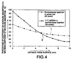
- FIG. 4 is a graph showing the moisture absorption distribution of a composite material in directions perpendicular thereto, wherein line 1 shows the moisture absorption distribution of a composite material after the elapse of 25 years under actual environment, and line 2 shows the moisture absorption distribution of a composite material which was moisture-absorbed for 36 weeks under a high humidity environment including a relative humidity of 95 %RH. Furthermore, the axis of ordinates denotes the percentage of a coefficient of moisture absorption to the maximum coefficient of moisture absorption, which shows the moisture content of a composite material per unit weight.
- the axis of abscissas denotes the distance from the surface of the composite material, which denotes the distance from the surface to the center of the composite material, i.e., to 10 mm, since the thickness of the composite material is 20 mm.
- the difference between the coefficients of moisture absorption of the surface and central portion of the composite material under actual environment is not so great, whereas the difference between the coefficients of moisture absorption of the surface and central portion of the composite material, which was moisture-absorbed in a short period of time under a high humidity environment, is greater. That is, the composite material, which was moisture-absorbed in a short period of time, can not accurately reproduce the moisture absorption state of the composite material under actual environment. Therefore, there is a problem in that the strength of the composite material, which is moisture-absorbed by the conventional moisture-absorbing method, can not be accurately evaluated as the thickness thereof increases. In particularly such a problem is remarkably caused in the case of a composite material having a thickness of 10 mm or more.
- a method for absorbing the moisture of a composite material under a high humidity environment so that the moisture absorption state of the composite material is equal to the moisture absorption state of a composite material after the elapse of predetermined years under actual environment wherein the moisture of the composite material is absorbed in a pressure container at a predetermined high temperature, a predetermined high humidity and a predetermined high pressure.
- the predetermined high temperature may be a temperature below the glass transition point of the composite material.
- the predetermined high temperature is preferably a temperature which is higher than 50 °C and lower than 140 °C when the composite material is made of an epoxy resin.
- the predetermined high humidity may be a relative humidity of 70 %RH or higher to 100 %RH or lower.
- the predetermined high pressure may be a pressure in the range of from 1400 hPa to 5000 hPa.
- the predetermined high pressure is preferably a pressure in the range of from 1400 hPa to 3000 hPa.
- a method for absorbing the moisture of a composite material under a high humidity environment so that the moisture absorption state of the composite material is equal to the moisture absorption state of a composite material after the elapse of predetermined years under actual environment wherein the moisture of the composite material is absorbed in a pressure container at a predetermined high temperature of the glass transition point of the composite material or lower, a predetermined high humidity of a relative humidity in the range of from 70 %RH to 100 %RH, and a predetermined high pressure of higher than atmospheric pressure.
- a method for absorbing the moisture of a composite material under a high humidity environment so that the moisture absorption state of the composite material is equal to the moisture absorption state of a composite material after the elapse of predetermined years under actual environment wherein the composite material in a pressure vessel, and the temperature, humidity and pressure in the pressure vessel are changed in accordance with a predetermined time table so that the moisture absorption distribution of the composite material in directions perpendicular thereto is equal to that of a composite material after the elapse of predetermined years under actual environment.
- the time table may be prepared by a numerical operation using an equation indicative of Fick law, Arrhenius equation, an equation indicative of the relationship between a relative humidity and a saturated coefficient of moisture absorption, and an equation indicative of the relationship between a coefficient of moisture absorption and a moisture concentration.
- the present invention it is possible to provide a desired moisture absorption distribution by changing conditions for temperature, humidity and pressure in a pressure vessel.
- a composite material having a required moisture absorption distribution which is equal to that of a composite material after the elapse of predetermined years under actual environment, and it is possible to accurately evaluate the strength of a composite material even if the composite material has a great thickness.
- the composite materials for use in this preferred embodiment include resin composite materials for use in airplanes, e.g., rotor hubs of helicopters.
- the resin composite materials supposed in this preferred embodiment include fiber reinforced composite materials.
- the resins include epoxy resins, and the reinforcing fibers include glass fibers.
- the resins of the composite materials may include polyimide resins, bismaleimide resins and phenol resins, and the reinforcing resins may include carbon fibers, ceramic fibers and alamide fibers.
- the composite materials for use in airplanes it is required to conduct a strength evaluating test, such as a bending test and a tension test, using a composite material which is in a moisture absorption state equal to that after the elapse of predetermined years under actual environment, so that it is required to absorb the moisture of the composite material in a short period of time.
- a strength evaluating test such as a bending test and a tension test
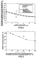
- FIG. 1 is a graph showing the relationship between the moisture absorption time and coefficient of moisture absorption of a composite material under various environments.
- the axis of abscissa denotes the moisture absorption time (h)
- the axis of ordinates denotes the coefficient of moisture absorption (%).
- line 3 is a graph on the same environmental conditions as those in the conventional moisture-absorbing method, i.e., on environmental conditions including a pressure of atmospheric pressure, a temperature of 71 °C and a relative humidity of 95 %RH
- line 4 is a graph on environmental conditions including an absolute pressure of 1485 hPa, a temperature of 120 °C and a relative humidity of 75 %RH
- line 5 is a graph on environmental conditions including an absolute pressure of 2953 hPa, a temperature of 133 °C and a relative humidity of 100 %RH
- line 6 is a graph on environmental conditions including an absolute pressure of 4852 hPa, a temperature of 151 °C and a relative humidity of 100 %RH.
- the high pressure is in the range of from 1400 hPa to 5000 hPa, preferably in the range of from 1400 hPa to 3000 hPa.
- the high temperature is selected so as not to exceed about 140 °C which the glass transition point of the epoxy resin.
- the high temperature is selected so as to be in the range of from 50 °C to 130 °C. Therefore, the temperature condition is suitably changed in accordance with the kind of the composite material.
- a composite material having a quantity of moisture absorption which is equal to that of a composite material after the elapse of predetermined years, e.g., 25 years, under actual environment, can be obtained in a short period of time by absorbing the moisture of the composite material under a high humidity environment using a pressure vessel.
- the composite material if the thickness of the composite material increases, the moisture absorption distribution of the composite material in the directions perpendicular thereto is different from that of a composite material under actual environment even if the quantity of moisture absorption is the same.
- the composite material supposed in this preferred embodiment is used for rotor hubs of helicopters, and has a thickness of about 20 to 40 mm, so that the moisture absorption distribution is greatly different only by equalizing the quantity of moisture absorption.
- the environment conditions in the pressure vessel are changed in a predetermined time table so as to also equalize the moisture absorption distribution.
- This time table uses the following basic equations (1) through (5) so as to obtain a predetermined moisture absorption distribution, and is determined by simulating the distribution by means of a computer.
- line 7 is a graph showing a moisture absorption distribution simulated by a computer in accordance with an example of a time table which is determined on the basis of the above described basic equations (1) through (5)
- line 8 is a graph showing a moisture absorption distribution simulated by a computer with respect to a composite material after the elapse of 25 years under actual environment.
- a first environment condition including a relative humidity of 80 %RH and a pressure of atmospheric pressure is held for 36 weeks
- a second environment condition including a relative humidity of 70 %RH and a pressure of atmospheric pressure is held for 8 weeks.
- the axis of abscissa of the graph denotes the distance from the surface of the composite material to the center, i.e., 10 mm
- the axis of ordinates thereof denotes the coefficient of moisture absorption of the composite material assuming that it is 100 % in the saturated state.
- lines 7 and 8 are substantially the same, and the moisture absorption distribution of the composite material under actual environment is substantially equal to the moisture absorption distribution of the composite material which is moisture-absorbed when the environmental condition in the pressure vessel is changed in accordance with the predetermined time table. This is more clear as compared with the graph of FIG. 4 showing the prior art.
- a time table which comprises a plurality of different environmental conditions for pressure, temperature and humidity, and predetermined periods of time corresponding to the respective environmental conditions, is previously determined by a simulation, and if the environmental conditions in a pressure vessel, in which a composite material is put, are changed on the basis of the time table, it is possible to obtain a composite material having a moisture absorption state which is substantially equal to that of a composite material under actual environment.
- the first and second environmental conditions are constant at atmospheric pressure in the graph of FIG. 2, the moisture of the composite material can be absorbed under a high humidity environment in a short period of time as shown in FIG. 1. Therefore, if the environmental condition is determined in view of this, it is possible to obtain a composite material having a desired moisture absorption state in a short period of time.
- the environmental conditions in the pressure vessel are set so as to include a high pressure, and the moisture of a composite material is absorbed by a quantity of moisture absorption which is equal to or higher than the quantity of moisture absorption of a composite material under a desired actual environment. Then, the environmental conditions are changed so as to have a desired moisture absorption distribution. That is, the moisture of the composite material is sufficiently absorbed in a short period of time at the initial stage, and the moisture absorption distribution is adjusted at the next stage. When the initial stage is completed, the moisture absorption distribution is different so that the coefficient of moisture absorption on the surface side is about 100 % and the moisture of the central portion is hardly absorbed.
- the environmental conditions are changed so as to decrease the coefficient of moisture absorption on the surface side and so as to increase the coefficient of moisture absorption of the inner part. Therefore, at this adjusting stage, the pressure is not always a high pressure, but the pressure is sometimes a pressure below atmospheric pressure.
- the time table for use in the present invention should not be limited to such a time table gradually and discontinuously changing the environmental conditions, but it may be a time table continuously changing environmental conditions, such as pressure and temperature.
- FIG. 3 is a graph showing the relationship between the proportion of the saturated coefficient of moisture absorption to the maximum coefficient of moisture absorption and the strength retaining percentage. As can be seen from this graph, there is an intimate relationship between the coefficient of moisture absorption and strength of the composite material, and the strength retaining percentage decreases as the percentage of the saturated coefficient of moisture absorption to the maximum coefficient of moisture absorption increases. Therefore, it can also be seen from the graph of FIG. 3 that it is required to sufficiently take account of the moisture absorption state in the evaluation of the strength of the composite material.
- the present invention by absorbing the moisture of a composite material under a high humidity environment in a pressure vessel, it is possible to absorb the moisture of the composite material to a predetermined quantity of moisture absorption in a shorter period of time than that in the conventional case.
- the present invention by changing the environmental condition in the pressure vessel in accordance with the predetermined time table, it is possible to obtain a composite material having a moisture absorption distribution which is equal to a moisture absorption distribution underactual environment.
Landscapes
- Life Sciences & Earth Sciences (AREA)
- Health & Medical Sciences (AREA)
- Chemical & Material Sciences (AREA)
- General Health & Medical Sciences (AREA)
- Immunology (AREA)
- Physics & Mathematics (AREA)
- Pathology (AREA)
- General Physics & Mathematics (AREA)
- Analytical Chemistry (AREA)
- Biochemistry (AREA)
- Biodiversity & Conservation Biology (AREA)
- Ecology (AREA)
- Environmental Sciences (AREA)
- Environmental & Geological Engineering (AREA)
- Engineering & Computer Science (AREA)
- Food Science & Technology (AREA)
- Medicinal Chemistry (AREA)
- Investigating Strength Of Materials By Application Of Mechanical Stress (AREA)
- Sampling And Sample Adjustment (AREA)
- Processing And Handling Of Plastics And Other Materials For Molding In General (AREA)
- Reinforced Plastic Materials (AREA)
Applications Claiming Priority (2)
| Application Number | Priority Date | Filing Date | Title |
|---|---|---|---|
| JP21427499 | 1999-07-28 | ||
| JP21427499A JP3233618B2 (ja) | 1999-07-28 | 1999-07-28 | 複合材の吸湿方法 |
Publications (2)
| Publication Number | Publication Date |
|---|---|
| EP1074841A2 true EP1074841A2 (de) | 2001-02-07 |
| EP1074841A3 EP1074841A3 (de) | 2001-08-29 |
Family
ID=16653029
Family Applications (1)
| Application Number | Title | Priority Date | Filing Date |
|---|---|---|---|
| EP20000116405 Withdrawn EP1074841A3 (de) | 1999-07-28 | 2000-07-28 | Verfahren zum Absorbieren der Feuchtigkeit eines Verbundwerkstoffes |
Country Status (3)
| Country | Link |
|---|---|
| US (1) | US6393726B1 (de) |
| EP (1) | EP1074841A3 (de) |
| JP (1) | JP3233618B2 (de) |
Families Citing this family (3)
| Publication number | Priority date | Publication date | Assignee | Title |
|---|---|---|---|---|
| JP3233618B2 (ja) * | 1999-07-28 | 2001-11-26 | 川崎重工業株式会社 | 複合材の吸湿方法 |
| GB0616119D0 (en) * | 2006-08-14 | 2006-09-20 | Airbus Uk Ltd | Method of producing structural components having improved toughness |
| US20160370309A1 (en) | 2015-06-22 | 2016-12-22 | The Boeing Company | Methods and systems for determining an allowable moisture content in a composite structure |
Family Cites Families (18)
| Publication number | Priority date | Publication date | Assignee | Title |
|---|---|---|---|---|
| DE1598899A1 (de) | 1967-06-19 | 1972-01-20 | Original Hanau Quarzlampen | Geraet zur Schnellpruefung der Licht- und Wetterechtheit verschiedener Stoffe |
| JPS5949531B2 (ja) | 1979-09-10 | 1984-12-03 | 富士通株式会社 | 透水試験法 |
| US4524040A (en) * | 1983-08-04 | 1985-06-18 | The Firestone Tire & Rubber Company | Process for making coated glass fiber reinforced composites |
| US4537917A (en) * | 1984-10-01 | 1985-08-27 | The Firestone Tire & Rubber Company | Composites and size coated glass fibers used therein |
| JPS62101421A (ja) | 1985-10-29 | 1987-05-11 | Teijin Ltd | ポリエチレンテレフタレ−トフイルムロ−ルの処理方法 |
| JPH0718790B2 (ja) | 1987-01-07 | 1995-03-06 | 住友ベークライト株式会社 | 半導体封止用樹脂の耐湿性評価方法 |
| JPH0210133A (ja) | 1988-06-28 | 1990-01-12 | Nec Corp | 水の拡散係数測定用プラスチック基板 |
| US5264279A (en) * | 1989-09-19 | 1993-11-23 | Dai Nippon Insatsu Kabushiki Kaisha | Composite thermal transfer sheet |
| FR2659085B1 (fr) * | 1990-03-02 | 1992-05-15 | Atochem | Composition coextrudable avec le polyfluorure de vinylidene permettant l'adhesion de ce dernier avec une resine polymerique non compatible - composite obtenu avec cette composition. |
| JP3286681B2 (ja) * | 1991-10-01 | 2002-05-27 | 東ソー株式会社 | ポリアリーレンスルフィド複合材料およびその製造方法 |
| US5954898A (en) * | 1994-05-13 | 1999-09-21 | Lockheed Fort Worth Company | Method and system for fabricating parts from composite materials |
| JP2644681B2 (ja) * | 1994-07-05 | 1997-08-25 | 工業技術院長 | 連結シリカ球状粒子からなる三次元網状構造体と樹脂とによる相互貫入型複合体およびその製造方法 |
| WO1996017006A1 (en) * | 1994-12-02 | 1996-06-06 | Toray Industries, Inc. | Prepreg and fiber-reinforced composite material |
| US5680713A (en) * | 1996-03-05 | 1997-10-28 | Hoechst Aktiengesellschaft | Process for the subcritical drying of aerogels |
| FR2746388B1 (fr) * | 1996-03-19 | 1998-06-05 | Aerospatiale | Procede de fabrication d'un panneau du type nid d'abeille en composite carbone/carbone ou carbone/ceramique et structures constituees a partir d'un tel panneau |
| US5718059A (en) * | 1996-09-25 | 1998-02-17 | Institute Of Paper Science And Technology, Inc. | Methods for dewatering solid-liquid matrices |
| US6092302A (en) * | 1997-04-25 | 2000-07-25 | 3M Innovative Properties Company | Absorbent fibrous granules |
| JP3233618B2 (ja) * | 1999-07-28 | 2001-11-26 | 川崎重工業株式会社 | 複合材の吸湿方法 |
-
1999
- 1999-07-28 JP JP21427499A patent/JP3233618B2/ja not_active Expired - Fee Related
-
2000
- 2000-07-27 US US09/626,910 patent/US6393726B1/en not_active Expired - Lifetime
- 2000-07-28 EP EP20000116405 patent/EP1074841A3/de not_active Withdrawn
Also Published As
| Publication number | Publication date |
|---|---|
| JP3233618B2 (ja) | 2001-11-26 |
| US6393726B1 (en) | 2002-05-28 |
| EP1074841A3 (de) | 2001-08-29 |
| JP2001041947A (ja) | 2001-02-16 |
Similar Documents
| Publication | Publication Date | Title |
|---|---|---|
| Ross et al. | NDE of wood-based composites with longitudinal stress waves | |
| Castro et al. | Fatigue and healing of asphalt mixtures: Discriminate analysis of fatigue curves | |
| Dahl et al. | Linear shear properties of spruce softwood | |
| Yoshihara et al. | Measurement of the shear modulus of wood by static bending tests | |
| Lal | Residual strength assessment of low velocity impact damage of graphite-epoxy laminates | |
| Tang et al. | Mechanical properties and strength grading of engineered bamboo composites in China | |
| EP1074841A2 (de) | Verfahren zum Absorbieren der Feuchtigkeit eines Verbundwerkstoffes | |
| Angst et al. | Moisture induced stresses perpendicular to the grain in glulam: review and evaluation of the relative importance of models and parameters | |
| Perillo et al. | A numerical/experimental study on the impact and CAI behaviour of glass reinforced compsite plates | |
| Sonderegger et al. | An investigation of the influence of selected factors on the properties of spruce wood | |
| Konnerth et al. | Elastic properties of adhesive polymers. III. Adhesive polymer films under dry and wet conditions characterized by means of nanoindentation | |
| Mittal et al. | Analysis of impact of a moving body on an orthotropic elastic plate | |
| Moarcas et al. | Determination of Poisson's ratio for particleboard in pure bending | |
| Martínez et al. | Impact characterization of a carbon fiber‐epoxy laminate using a nonconservative model | |
| Collings | Moisture management and artificial ageing of fibre reinforced epoxy resins | |
| Bonnin et al. | Response of a packaging system to a transient event: real‐time replication versus shock response spectra simulation | |
| Soderquist | Design/certification considerations in civil composite aircraft structure | |
| Lynth et al. | Prediction equations for centers of gravity and moments of inertia of loblolly pine stems | |
| Kuhlmann et al. | Guidelines for a Finite Element Based Design of Timber Structures | |
| Kanellopoulos et al. | Hygrothermal characteristics of carbon fibre reinforced plastics | |
| Nicholas et al. | Finite Element Modeling of Mode I Failure of the Single Contoured Cantilever CFRP‐Reinforced Concrete Beam | |
| Levy et al. | CERTIFICATION OF KEVLAR ON PRIMARY STRUCTURE SAAB/FAIRCHILD SF-340 AIRCRAFT | |
| Liu et al. | Nature of knot checks developed during seasoning of radiata pine sawn boards | |
| Butterfield et al. | Combined Experiment Phase 1.[Horizontal axis wind turbines: wind tunnel testing versus field testing] | |
| Boards | E Rport |
Legal Events
| Date | Code | Title | Description |
|---|---|---|---|
| PUAI | Public reference made under article 153(3) epc to a published international application that has entered the european phase |
Free format text: ORIGINAL CODE: 0009012 |
|
| 17P | Request for examination filed |
Effective date: 20000728 |
|
| AK | Designated contracting states |
Kind code of ref document: A2 Designated state(s): AT BE CH CY DE DK ES FI FR GB GR IE IT LI LU MC NL PT SE |
|
| AX | Request for extension of the european patent |
Free format text: AL;LT;LV;MK;RO;SI |
|
| PUAL | Search report despatched |
Free format text: ORIGINAL CODE: 0009013 |
|
| AK | Designated contracting states |
Kind code of ref document: A3 Designated state(s): AT BE CH CY DE DK ES FI FR GB GR IE IT LI LU MC NL PT SE |
|
| AX | Request for extension of the european patent |
Free format text: AL;LT;LV;MK;RO;SI |
|
| AKX | Designation fees paid |
Free format text: DE FR GB |
|
| 17Q | First examination report despatched |
Effective date: 20041022 |
|
| STAA | Information on the status of an ep patent application or granted ep patent |
Free format text: STATUS: THE APPLICATION IS DEEMED TO BE WITHDRAWN |
|
| 18D | Application deemed to be withdrawn |
Effective date: 20050302 |