EP1074773A1 - Collier de support de câble et dispositif de fixation associé - Google Patents
Collier de support de câble et dispositif de fixation associé Download PDFInfo
- Publication number
- EP1074773A1 EP1074773A1 EP00306567A EP00306567A EP1074773A1 EP 1074773 A1 EP1074773 A1 EP 1074773A1 EP 00306567 A EP00306567 A EP 00306567A EP 00306567 A EP00306567 A EP 00306567A EP 1074773 A1 EP1074773 A1 EP 1074773A1
- Authority
- EP
- European Patent Office
- Prior art keywords
- bracket
- stem
- cable support
- support bracket
- laterally extending
- Prior art date
- Legal status (The legal status is an assumption and is not a legal conclusion. Google has not performed a legal analysis and makes no representation as to the accuracy of the status listed.)
- Withdrawn
Links
Images


Classifications
-
- H—ELECTRICITY
- H02—GENERATION; CONVERSION OR DISTRIBUTION OF ELECTRIC POWER
- H02G—INSTALLATION OF ELECTRIC CABLES OR LINES, OR OF COMBINED OPTICAL AND ELECTRIC CABLES OR LINES
- H02G3/00—Installations of electric cables or lines or protective tubing therefor in or on buildings, equivalent structures or vehicles
- H02G3/26—Installations of cables, lines, or separate protective tubing therefor directly on or in walls, ceilings, or floors
- H02G3/263—Installation, e.g. suspension, of conduit channels or other supports
-
- F—MECHANICAL ENGINEERING; LIGHTING; HEATING; WEAPONS; BLASTING
- F16—ENGINEERING ELEMENTS AND UNITS; GENERAL MEASURES FOR PRODUCING AND MAINTAINING EFFECTIVE FUNCTIONING OF MACHINES OR INSTALLATIONS; THERMAL INSULATION IN GENERAL
- F16L—PIPES; JOINTS OR FITTINGS FOR PIPES; SUPPORTS FOR PIPES, CABLES OR PROTECTIVE TUBING; MEANS FOR THERMAL INSULATION IN GENERAL
- F16L3/00—Supports for pipes, cables or protective tubing, e.g. hangers, holders, clamps, cleats, clips, brackets
- F16L3/02—Supports for pipes, cables or protective tubing, e.g. hangers, holders, clamps, cleats, clips, brackets partly surrounding the pipes, cables or protective tubing
-
- F—MECHANICAL ENGINEERING; LIGHTING; HEATING; WEAPONS; BLASTING
- F16—ENGINEERING ELEMENTS AND UNITS; GENERAL MEASURES FOR PRODUCING AND MAINTAINING EFFECTIVE FUNCTIONING OF MACHINES OR INSTALLATIONS; THERMAL INSULATION IN GENERAL
- F16L—PIPES; JOINTS OR FITTINGS FOR PIPES; SUPPORTS FOR PIPES, CABLES OR PROTECTIVE TUBING; MEANS FOR THERMAL INSULATION IN GENERAL
- F16L3/00—Supports for pipes, cables or protective tubing, e.g. hangers, holders, clamps, cleats, clips, brackets
- F16L3/22—Supports for pipes, cables or protective tubing, e.g. hangers, holders, clamps, cleats, clips, brackets specially adapted for supporting a number of parallel pipes at intervals
-
- F—MECHANICAL ENGINEERING; LIGHTING; HEATING; WEAPONS; BLASTING
- F16—ENGINEERING ELEMENTS AND UNITS; GENERAL MEASURES FOR PRODUCING AND MAINTAINING EFFECTIVE FUNCTIONING OF MACHINES OR INSTALLATIONS; THERMAL INSULATION IN GENERAL
- F16L—PIPES; JOINTS OR FITTINGS FOR PIPES; SUPPORTS FOR PIPES, CABLES OR PROTECTIVE TUBING; MEANS FOR THERMAL INSULATION IN GENERAL
- F16L3/00—Supports for pipes, cables or protective tubing, e.g. hangers, holders, clamps, cleats, clips, brackets
- F16L3/24—Supports for pipes, cables or protective tubing, e.g. hangers, holders, clamps, cleats, clips, brackets with a special member for attachment to profiled girders
- F16L3/243—Supports for pipes, cables or protective tubing, e.g. hangers, holders, clamps, cleats, clips, brackets with a special member for attachment to profiled girders the special member being inserted in the profiled girder
Definitions
- the present invention relates generally to cable supports and more particularly, to cable support brackets that maintain the natural gradual bend radius of cables that extend thereacross.
- the present invention is particularly useful for category 5 cable and high performance communications cable, including fiber optic cable that may be suspended or mounted in a hanging manner on any surface in the utilitarian part of a building such as a wall, ceiling, joist, the area above a drop ceiling or similar such surface or area.
- Attenuation is the loss of power or signal strength along the transmission medium.
- Cross-talk is an unwanted transmission from another nearby cable, or even a pair in the same cable.
- Return loss is a measure of degree of impedance between the cable and a connector. Background noise is also an irritating problem resulting from a low signal-to-noise ratio. Inadequate cable installation is a key reason for such factors, especially when data and voice transmission speeds are continually being increased.
- Such cables should not be kinked, snaked, bent sharply, tugged, sag excessively, or come into engagement with sharp edges, or be too close to power cables.
- the wiring can be placed under the floor with elevated flooring which is extremely expensive and often not practical. A more common place for such wiring is above the ceiling between the structural floor or roof above, and a dropped or acoustical ceiling.
- New buildings may be designed with such cables in mind and include cable trays.
- Cable trays are simply suspended or cantilevered trays in which such cables can be laid flat to extend horizontally, and hung or suspended from beams, joists, or decking for example, oftentimes by trapeze hangers.
- Such trays can be retrofitted into existing buildings, but not easily or economically, particularly if there is not a significant amount or extent of open or unobstructed horizontal space above the ceilings.
- the area above drop ceilings is typically cluttered with structural members such as beams or open joists, utilities such as plumbing or sprinkler systems, HVAC ducts, conventional power wiring, often encased in conduits, and suspension hangers for the ceiling and any lighting or other fixtures in the ceiling.
- most beams, joists and other structures extend in a rectilinear fashion above a ceiling, while communications or data cabling usually radiates from a panel or closet in a star topology.
- Such cable support accommodates and supports the natural bend radius of the cables that lay thereacross.
- Such cable support is for the installation in utilitarian areas of a building, which can be fastened to or supported directly or indirectly from anything encountered.
- the present invention provides a cable support bracket that advantageously accommodates, supports and maintains the natural gradual bend radius of suspended cables that extend across the support bracket.
- a cable support having a hook-like shaped body including an elongate stem portion, an elongate laterally extending portion extending generally perpendicularly from one end of the stem portion; and an elongate up-turned end portion extending perpendicularly from one end of the laterally extending portion, generally parallel to the stem portion.
- the stem portion, the laterally extending portion, and the end portion define a cable support saddle for accommodating cables thereacross with the laterally extending portion including a convex cable support surface for maintaining a gradual bend radius for the cables extending thereacross.
- Support bracket of the present invention may be attached to a structure with fasteners, hangers, clips and combinations thereof.
- the laterally extending portion of the support bracket is contiguous with both the stem portion and the end portion, with a short-radius right-angle transition between the main stem portion and the laterally extending portion as well as between the laterally extending portion and the end portion.
- the laterally extending portion extends between the stem and the end portion along a plane perpendicular to both the main stem portion and the end portion for a distance approximately equal to the length of the end portion, as opposed to a semi-circular configuration as would be present in a typical J-hook configuration.
- the inventive support bracket is a hook-like shaped fastener, in a form of a modified "J" type structure formed by the stem, the laterally extending portion and the end portion defining the interior saddle area of the modified "J".
- the interior saddle area defines the cable support saddle surface projecting in a generally planar manner along the laterally extending portion and along a general plane which is perpendicular to the main stem portion for supporting a cable.
- This cable support saddle surface has a convex curved surface extending along the axis of the hook in a direction of the cable.
- Such convex curved saddle surface includes a curved center portion which gradually slopes in a convex shape toward the side portions of the support bracket. This convex shape accommodates and maintains the natural gradual bend radius exhibited by the cables that extend across the cable support bracket.
- the side portions of the support bracket sharply transition in a very short radius at an angle perpendicular to the general plane or axis of the cable supporting surface of the support bracket, forming opposing parallel flanges for strengthening the structure of the support bracket.
- Such opposing flanges are perpendicular to the general plane of the interior surface which defines the cable supporting surface and are parallel with respect to each other.
- the opposing flanges reinforce the strength of the support bracket and do not assist in supporting the cables being supported by the bracket.
- the flanges are situated so that they will not contact or affect the position of the supported cables.
- the stem of the cable support bracket of the present invention includes a pair of hangers that are integrally formed from the support bracket by a cut-out portion of the planar surface of the stem portion. Such hangers permit attachment of the support bracket to a desired structure, such as a wall. Additionally, a pair of clips may be integrally formed from the support bracket by a cut-out portion of the planar surface of the stem. In this embodiment, the cable support bracket may also include fastener apertures located on the stem portion.
- the stem includes non-threaded apertures therein that can accommodate conventional fasteners for securement of the bracket to a desired structure. Additionally, this embodiment may also include a pair of brackets and/or clips useful to secure the cable support bracket to a structure.
- a cable supported by the interior surface of the support bracket can be maintained in place, for example, by wrapping a tie, such as a cable tie, about the cable and the support bracket in a cross-wise manner. More particularly, a cable tie can be wrapped about a cable supported within the support bracket such that the cable tie extends from the flange at one edge of the support bracket near the transition between the main stem portion and the laterally extending portion, wrapping around the cable, and extending to the opposing flange at the other edge of the support bracket near the transition between the end portion and the laterally extending portion. In this manner, the cable tie contacts the cable and maintains the cable in a tight manner within the interior surface of the support bracket against the cable supporting surface of the laterally extending portion.
- a tie such as a cable tie
- the support bracket With the support bracket attached to a wall or similar surface, a cable can be supported within the saddle of the support bracket in a hanging fashion.
- the support bracket is mountable on a wall, ceiling, joist, or similar such surface for supporting one or more cables, such as a bundle of fiber optic cables or the like, in a hanging manner.
- the support bracket can be quickly fastened to a wide variety of structures, walls or studs, beam or angle flanges, C-purlins or Z-purlins, with screw-on or hammer-on fasteners, or even drop wires, rods or vertical flanges with other types of fasteners.
- a number cable support brackets of the present invention can be assembled to each side of hanging tree bracket and the bracket in-turn secured to a beam flange or joist, for example with another fastener.
- the bracket can also be used inverted with yet another fastener to elevate the support above the structure such as a Tec bar of a suspended ceiling grid.
- cables can be supported to avoid placing pressure or stress on the cable, or pinching or kinking the cable.
- the spacing may be such that excessive sag between supports is avoided,
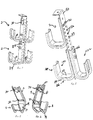
- Figure 1 is a plan view of the cable support bracket of the present invention.
- Figure 2 is a front plan view of the stem portion of the cable support bracket of the present invention.
- Figure 3 is a rear plan view of the stem portion of the cable support bracket of the present invention.
- Figure 4 is a plan view of the cable support bracket of the present invention.
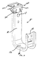
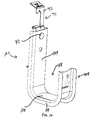
- Figure 5 is a perspective view of the cable support bracket of the present invention.
- Figure 6 is a perspective view of the cable support bracket of the present invention.
- Figure 7 is a perspective view of a number of cable support brackets of the present invention secured to a hanging structure.
- Figure 8 is a perspective view of a number of cable support brackets of the present invention secured to a hanging structure.
- Figure 9 is a perspective view of the cable support bracket of the present invention attached to a beam by a hammer-on beam flange clip.
- Figure 10 is an enlarged view of the cable support bracket of the present invention attached to a hammer-on beam flange clip.
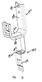
- Figure 11 is a perspective view of the cable support bracket of the present invention connected to clip in turn secured to a drop wire.
- Figure 12 is an enlarged perspective view of the cable support bracket of the present invention connected to clip useful for attaching the bracket to a drop wire.
- Figure 13 is a perspective view of the cable support bracket of the present invention connected to a hammer-on beam flange clip secured to a beam flange.
- Figure 14 is a perspective view of the cable support bracket of the present invention connected to a hammer-on beam flange clip useful in securing the bracket to a beam flange.
- Figure 15 is a perspective view of the cable support bracket of the present invention connected to a clip suspended from a beam.
- Figure 16 is an enlarged perspective view of the cable support bracket of the present invention connected to a clip useful for suspending the bracket from a beam.
- Figure 17 is a perspective view of the cable support bracket of the present invention connected to a clip suspended from a C-purlin.
- Figure 18 is an enlarged perspective view of the cable support bracket of the present invention connected to a clip useful in suspending the bracket from a C-purlin.
- Figure 19 is a perspective view of the cable support bracket of the present invention secured to a screw on beam flange clamp.
- Figure 20 is an enlarged perspective view of the cable support bracket of the present invention secured to a screw on beam flange clamp.
- Figure 21 is a perspective view of the cable support bracket of the present invention secured to a bracket attachment.
- Cable support bracket 2 useful for supporting cables, is shown in Figures 1-4.
- Cable support bracket 2 includes stem portion 4, elongate laterally extending portion 6 and elongate up-turned end portion 8.
- Elongate laterally extending portion 6 is generally perpendicular from one end of the stem portion 4 and elongate up-turned end portion 8 extends perpendicularly from the other end of the laterally extending portion and is generally parallel to stem 2.
- the configuration of stem 4, laterally extending portion and elongate up-turned end portion are in a hook-like shaped body.
- Stem 4, laterally extending portion 6 and end 8 define the interior of cable support bracket, saddle area 18.
- Cable support saddle surface 10 accommodates cables 12 thereacross.
- Saddle surface 10 has a convex curved surface capable of supporting and maintaining the natural gradual bend radius of the cables that extend thereacross.
- Laterally extending portion 6 is contiguous with both, stem 4 and end 8.
- a pair of outwardly extending contiguous reinforcing flanges 14 run along the longitudinal edges of bracket 2.
- Flanges 14 extend from both sides of support bracket 2 at a right angle from stem 4, laterally extending portion 6 and end portion 8. Flanges act to reinforce the bracket and extend from the cable support saddle so as to not interfere with the supported cables.
- Flanges 14 extend on both sides of support bracket 2 throughout the length of the support bracket including both, end portion 8 and stem 4.
- stem 4 has a height about twice the diameter of the laterally extending portion 4 and about twice the height of the elongate up-turned end portion.
- the stem includes several apertures useful in securing the support bracket to a structure.
- Apertures 20 and 22 are located in the middle of the upper stem area. Apertures are designed to accommodate bolts 134 as shown in Figure 7-8.
- the support bracket of the present invention may be attached to a structure so that the support bracket 2 hangs therefrom and saddle surface 10 can easily accommodate cables 12 thereon.
- Several different attachment techniques are contemplated for the support brackets of the present invention. As shown in Figures 7-8, support bracket 2 is attached to structure 50 by a pair of hangers 30 and clips 32. Support bracket 102 is attached to structure 50 by conventional fasteners such as bolts 134 and nuts 136.
- a pair of hangers 30 and clips 32 are provided to secure the support bracket 2 to a desired structure, such as mounting bracket 50 or a wall. As shown in Figures 7-8, to secure bracket 2 to the desired structure, clips 32 arc inserted into apertures 52 of structure 50 and hangers 30 snap into apertures 52 to securely fasten support bracket 2 to structure 50.
- Hangers 30 and clips 32 are integrally formed from the support bracket by a cut-out portion of the planar interior surface of stem portion 4.
- Hangers 30 and clips 32 extend outwardly in a generally perpendicular manner to stem 4 and away from saddle area 18.
- Hangers 30 are configured so that they can snap into place in accommodating aperture 52 and stay secured to the desired structure.
- Clips 32 have a pair of downwardly facing hooks 33 that latch into place against accommodating apertures 52.
- support bracket 2 is secured to a structure that has a configuration of apertures 52 that accommodate both brackets 30 and clips 32 of support bracket 2, as shown in Figures 7-8.
- cable support bracket 102 in another embodiment of the present invention, has a plurality of apertures that accommodate fasteners therethrough.
- fasteners 134 extend through aperture 22 and/or 24 and the desired structure.
- support bracket 102 is secured to a structure that has a configuration of apertures that closely conform to the apertures of the support bracket.
- Useful fasteners include rivets, bolt fasteners and combinations thereof.
- cable support bracket 102 is secured by bolts 134 and nuts 136.
- An embodiment of the present invention provides for securing the cables in the saddle.
- a cable tie (not shown) may be used to secure the cables to the bracket support. More particularly, a cable tie can be wrapped about cables 12 supported on saddle surface 10 such that the cable tie extends from flange 14 at one edge of support bracket 2 near the transition between stem portion 4 and the laterally extending portion 6, wrapping around cable 12, and extending the cable tie to opposing flange 14 at other side edge of support bracket 2 near the transition between the end portion 8 and the laterally extending portion 6. Cable tie (not shown) contacts the cable and maintains the cable in a tight manner against the saddle surface 10 of laterally extending portion 6.
- cable support bracket 2 is attached to a beam 62 which includes a top flange 63, a bottom flange 64 and a web 65 therebetween.
- the lower flange 64 has an edge 66 which is capable of receiving a variety of hammer-on or screw-on clamps or clips.
- support 102 is secured to bottom edge 66 of the bottom flange 64 by a hammer-on flange clip 200.
- Hammer-on flange clip 200 is generally U-shaped and is made of spring steel having flexible top and bottom legs which spread as the clip is hammered on the flange. The edges of the top and bottom legs are provided with barbs 201 which bite into the flange to resist removal.
- the clip may be hammered onto the flange edge simply by using a hammer to strike the bight portion 202 of the clip.
- the bight portion of the clip includes a downwardly extending tab 203 provided with an aperture which accommodates rivet 47.
- Figure 10 shows a close up perspective view of cable support 102 connected to a hammer-on flange clip 200.
- FIG 11 shows the cable support bracket of the present invention connected to a drop wire 70.
- Drop wires or rods are often used to support various items or utilities from structural components or ceilings.
- Cable support bracket 102 is connected by rivet 47 to clip 71 which is connected to drop wire 70. Rivet 47 is secured to the approximate middle of the clip and the clip includes upper and lower spring legs although only upper leg 72 is visible. Spring legs are bent toward each other to create a lateral notch opening for receipt of the drop wire and when the legs are released on the wire or rod, sharp notch edges bite into and grip drop wire 70.
- Clip 71 is typical of multi-function clips for securing various items to drop wires, rods or flanges. Cable support 102 may be positioned vertically anywhere along drop wire 70.
- Figure 12 shows an expanded view of cable support 102 attached to clip 71 without a wire or rod attached thereto.
- cable support 102 is mounted to edge 64 of beam 62 via a hammer-on clip 80, similar to clip 200 in Figure 9.
- Cable support 102 is secured to clip 80 by the face of vertical leg 88 by rivet 47.
- Support bracket is secured to bottom edge 66 by hammer-on flange clip 80.
- Flange clip 80 is generally U-shaped and is made of spring steel having flexible top and bottom legs which spread as the clip is hammered on flange 64. The edges of the top and bottom legs are provided with barbs 82 which bite into flange 64 to resist removal.
- An enlarged view of clip 80 attached to cable support 102 is shown in Figure 14.
- Figure 15 illustrates beam 210 which has a vertical web 215 and opposite horizontal flange 217 which terminate in angled flange 219. Cable support 102 is connected to clip 90 by rivet 47.
- Clip 90 has a top hook 92 which snaps over edge of flange 219. Hook 92 includes barbs adapted to bite into the flange 219 to resist withdrawal.
- Figure 16 is an enlarged view of clip 90 as attached to cable support 102.
- Cable support 102 is connected to C-purlin structure 220 by a C-purlin clip 222, as shown in Figure 17.
- C-purlin 220 is a C-shaped structure and includes an upturned flange 227 having edge 228. Cable support 102 is attached to the lower end of C-purlin clip 222 with rivet 47.
- Upper end 221 of C-purlin clip 222 includes a hook 224 with barbed edges which fits over edge 228 and such barbed edges resist dislocation.
- Figure 18 is an enlarged view of cable support 102 attached to C-purlin clip 222.
- FIGs 19-20 show cable support 102 attached to screw-on beam hanger 230.
- screw-on beam hanger is useful in attaching cable support 102 to beam 62 onto edge 66.
- screw-on hanger 230 has bolt 235 threaded above and projecting into mouth 236 of screw-on hanger 230. The lower edge of mouth 236 is defined by teeth 237.
- Cable support bracket 102 is secured to beam 62 by tightening screw 235 onto edge 66 so that screw and teeth bite into beam 62.
- Hanger 230 is secured to cable support 102 by rivet 47.
- Figure 20 shows an enlarged view of cable support 102 as attached to screw-on hanger 230.
- Figure 21 shows cable support 102 secured to bracket attachment 240 by rivet 47.
- Bracket attachment 240 bends at surface 242 and is connected to clip 248 by rivet 247.
- Bracket attachment 240 attaches to a structure by clip 242.
- the support bracket of the present invention is preferably made of a metallic material and desirably formed from a continuous strip of metal. The strips of metal are formed and then the support bracket is formed by appropriately shaping of the metal strip.
- the shaped support bracket may be heat treated and then coated or galvanized. Spring steel or stainless steel may be employed to make the saddle support.
Landscapes
- Engineering & Computer Science (AREA)
- General Engineering & Computer Science (AREA)
- Mechanical Engineering (AREA)
- Architecture (AREA)
- Civil Engineering (AREA)
- Structural Engineering (AREA)
- Installation Of Indoor Wiring (AREA)
- Details Of Indoor Wiring (AREA)
- Supports For Pipes And Cables (AREA)
- Hooks, Suction Cups, And Attachment By Adhesive Means (AREA)
Applications Claiming Priority (2)
| Application Number | Priority Date | Filing Date | Title |
|---|---|---|---|
| US14687299P | 1999-08-03 | 1999-08-03 | |
| US146872P | 1999-08-03 |
Publications (1)
| Publication Number | Publication Date |
|---|---|
| EP1074773A1 true EP1074773A1 (fr) | 2001-02-07 |
Family
ID=22519352
Family Applications (1)
| Application Number | Title | Priority Date | Filing Date |
|---|---|---|---|
| EP00306567A Withdrawn EP1074773A1 (fr) | 1999-08-03 | 2000-08-02 | Collier de support de câble et dispositif de fixation associé |
Country Status (4)
| Country | Link |
|---|---|
| US (1) | US6565048B1 (fr) |
| EP (1) | EP1074773A1 (fr) |
| JP (1) | JP2001095133A (fr) |
| CA (1) | CA2315025A1 (fr) |
Cited By (4)
| Publication number | Priority date | Publication date | Assignee | Title |
|---|---|---|---|---|
| EP1201980A2 (fr) * | 2000-10-30 | 2002-05-02 | Framatome Connectors International | Dispositif de maintien pour lignes d'alimentation aux bâtiments |
| WO2005100836A1 (fr) * | 2004-04-15 | 2005-10-27 | Øglænd System As | Dispositif de connexion de support |
| WO2008152329A1 (fr) | 2007-06-04 | 2008-12-18 | Free | Support pour cable a fibre optique |
| WO2009032550A1 (fr) | 2007-08-29 | 2009-03-12 | Erico International Corporation | Support de câble et procédé |
Families Citing this family (62)
| Publication number | Priority date | Publication date | Assignee | Title |
|---|---|---|---|---|
| US7025712B2 (en) * | 2002-09-05 | 2006-04-11 | Marco Parrilla | Suspended squat rack |
| US6729096B1 (en) * | 2002-09-09 | 2004-05-04 | Aaon Inc. | System for installing suspended ceiling |
| US7520476B2 (en) | 2002-12-11 | 2009-04-21 | Panduit Corp. | Cable support system |
| US6945501B2 (en) * | 2003-09-16 | 2005-09-20 | Thompson William J | Communication cable support structure and apparatus and method for making |
| US7073761B2 (en) * | 2004-01-16 | 2006-07-11 | Bellsouth Intellectual Property Corporation | Communication cable support |
| DE102004021513B4 (de) * | 2004-04-30 | 2012-05-16 | Airbus Operations Gmbh | Einhängklemmhalter für eine Trägerstruktur |
| EP1591672B1 (fr) * | 2004-04-30 | 2007-11-07 | Airbus Deutschland GmbH | Clip de suspension pour une structure de support |
| US20060038091A1 (en) * | 2004-08-18 | 2006-02-23 | Gregg Winn | Cable tray system |
| US7407138B1 (en) | 2005-01-24 | 2008-08-05 | Arlington Industries, Inc. | Gangable cable support with improved stiffness |
| US20070108357A1 (en) * | 2005-11-17 | 2007-05-17 | Plowman Daniel L | Support bracket for bicycles |
| US20070257157A1 (en) * | 2006-05-02 | 2007-11-08 | Chao-Hui Lu | Frame structure for holding a helical hose assembly |
| US20080093510A1 (en) * | 2006-10-23 | 2008-04-24 | Oh Michael H-S | Cable support and method |
| FR2911438B1 (fr) * | 2007-01-11 | 2011-05-13 | Icm Group | Dispositif de suspension |
| SE530980C2 (sv) * | 2007-03-14 | 2008-11-04 | Wibe Ab | Anordning vid kabelstege |
| US7501576B2 (en) * | 2007-06-12 | 2009-03-10 | Gagliardi Thomas P | Ceiling raceway |
| WO2009117319A1 (fr) * | 2008-03-18 | 2009-09-24 | Erico International Corporation | Support de câble et procédé servant à poser une longueur de câble |
| US8240619B2 (en) * | 2008-05-15 | 2012-08-14 | Orbit Industries, Inc. | Cable bracket |
| US20100102175A1 (en) * | 2008-10-29 | 2010-04-29 | Forrest Allen Dockery | Cable support |
| US8360372B2 (en) | 2009-02-27 | 2013-01-29 | Reginald David Gilbert | Stackable cable hanger |
| US20100224738A1 (en) * | 2009-03-09 | 2010-09-09 | William Bourgeois | Cable support device |
| DE102009019468A1 (de) * | 2009-05-04 | 2010-11-25 | Waldemar Rothe | Verbindungselement für Rohre, Verfahren zum Verbinden von Rohren und Verwendung des Verbindungselementes |
| JP4750875B2 (ja) * | 2009-05-11 | 2011-08-17 | 株式会社ブレスト工業研究所 | 長尺物支持具 |
| US9671046B2 (en) * | 2009-09-30 | 2017-06-06 | Thomas & Betts International Llc | Cable suspension assembly |
| US7837156B1 (en) | 2009-10-19 | 2010-11-23 | Jordan Handler | Cable support hook |
| US8257784B2 (en) | 2010-08-10 | 2012-09-04 | Toyota Motor Engineering & Manufacturing North America, Inc. | Methods for identifying articles of manufacture |
| US8616512B2 (en) * | 2010-09-23 | 2013-12-31 | Illinois Tool Works Inc. | Multi-purpose cable support having bendable stem |
| USD754775S1 (en) | 2011-03-10 | 2016-04-26 | John W. Hayes | Portable mounting assembly |
| US8882053B2 (en) * | 2011-10-19 | 2014-11-11 | Agco Corporation | Plumbing mount for agricultural sprayer |
| JP5546032B2 (ja) * | 2011-11-01 | 2014-07-09 | 学 枦山 | プール用コースロープ保持具 |
| CN103308244A (zh) * | 2012-03-15 | 2013-09-18 | 鸿富锦精密工业(深圳)有限公司 | 压差传感器的导管组合 |
| US8727288B2 (en) * | 2012-04-03 | 2014-05-20 | Commscope, Inc. Of North Carolina | Snap-in bracket for attaching cabling to a support |
| US9145052B2 (en) * | 2012-10-17 | 2015-09-29 | Dbg | Vehicle fuel tank mounting assembly and installation method |
| USD753472S1 (en) * | 2013-07-01 | 2016-04-12 | 3M Innovative Properties Company | Hook |
| US20150078809A1 (en) * | 2013-09-15 | 2015-03-19 | Richard Gregg Winn | Cable tray splice and support |
| US10720263B2 (en) | 2013-10-31 | 2020-07-21 | Electrical Materials Company | Electrical cable support arrangement |
| JP5631476B1 (ja) * | 2013-11-18 | 2014-11-26 | 株式会社ティ・エス・ケー | ケーブル支持金物 |
| EP2886947B1 (fr) * | 2013-12-20 | 2018-06-06 | Tego System Holding AB | Dispositif de montage pour appareil électrique sur une poutre de plafond |
| US9644766B2 (en) | 2014-05-20 | 2017-05-09 | O'Brien Holding Co., Inc. | Support for tubing |
| USD761638S1 (en) * | 2015-04-24 | 2016-07-19 | Caterpillar Inc. | Hook |
| US10030446B2 (en) * | 2015-08-18 | 2018-07-24 | Intelligent Designs 2000 Corp. | Vehicle ladder attachment mechanism |
| US9874296B2 (en) * | 2016-01-31 | 2018-01-23 | The Boeing Company | Snap-in duct support saddle |
| USD882119S1 (en) | 2016-12-30 | 2020-04-21 | Intelligent Designs 2000 Corp. | Vehicle ladder |
| CN108270177B (zh) * | 2016-12-30 | 2020-08-18 | 喜利得股份公司 | 保持器 |
| US20190107248A1 (en) | 2017-04-10 | 2019-04-11 | Shining Sea Trading Company | Devices for Hanging Items from Horizontally-Oriented Structures, and Associated Methods |
| CN207526678U (zh) * | 2017-11-29 | 2018-06-22 | 苏州优德通力科技有限公司 | 一种多用途浮子安装支架 |
| US10843057B2 (en) * | 2017-12-18 | 2020-11-24 | Stephanie Harris | Handle for dance practice assembly |
| EP3790428A1 (fr) * | 2018-05-08 | 2021-03-17 | Infinitas R & D Limited | Ensemble meuble modulaire et procédé associé |
| CN109009846A (zh) * | 2018-05-25 | 2018-12-18 | 浙江省荣军医院 | 一种多功能三叶草型手术床旁托举装置 |
| WO2020146531A1 (fr) * | 2019-01-09 | 2020-07-16 | Hubbell Incorporated | Attache-câbles pour la gestion de fils |
| US10920910B1 (en) | 2019-10-08 | 2021-02-16 | Arlington Industries, Inc. | Stackable cable hanger with latching feature |
| CN110912499A (zh) * | 2019-12-19 | 2020-03-24 | 朱国浩 | 一种用于安装太阳能光伏组件的挂钩 |
| CA3175665A1 (fr) * | 2020-04-17 | 2021-10-21 | Scott Robert RAND | Dispositifs de suspension de cables |
| US11870228B2 (en) | 2021-03-01 | 2024-01-09 | Panduit Corp. | Trapeze support bracket for a wire basket |
| US11881694B2 (en) | 2021-04-19 | 2024-01-23 | Erico International Corporation | Data cable support |
| KR102384920B1 (ko) * | 2021-05-12 | 2022-04-11 | 정상열 | 케이블 트레이 커버용 잠금장치 |
| USD1008007S1 (en) | 2022-06-24 | 2023-12-19 | Hubbell Incorporated | Cable hanger |
| USD1007286S1 (en) | 2022-06-24 | 2023-12-12 | Hubbell Incorporated | Cable hanger |
| USD1007285S1 (en) | 2022-06-24 | 2023-12-12 | Hubbell Incorporated | Cable hanger |
| USD1008006S1 (en) | 2022-06-24 | 2023-12-19 | Hubbell Incorporated | Cable hanger |
| USD1007284S1 (en) | 2022-06-24 | 2023-12-12 | Hubbell Incorporated | Cable hanger |
| USD1008004S1 (en) | 2022-06-24 | 2023-12-19 | Hubbell Incorporated | Cable hanger |
| USD1017388S1 (en) | 2022-10-01 | 2024-03-12 | Hubbell Incorporated | Cable hanger |
Citations (4)
| Publication number | Priority date | Publication date | Assignee | Title |
|---|---|---|---|---|
| US2968850A (en) * | 1958-03-10 | 1961-01-24 | George A Tinnerman | Supporting clamps |
| DE2642785A1 (de) * | 1975-09-26 | 1977-04-07 | Fimo S A | Vorrichtung zum aufhaengen von elektrischen kabeln o.dgl. |
| GB1577726A (en) * | 1976-07-02 | 1980-10-29 | Bicc Ltd | Support fittings |
| US5740994A (en) * | 1996-12-26 | 1998-04-21 | Erico International Corporation | Cable support and method |
Family Cites Families (19)
| Publication number | Priority date | Publication date | Assignee | Title |
|---|---|---|---|---|
| US622778A (en) | 1899-04-11 | nordyke | ||
| US887272A (en) | 1907-04-09 | 1908-05-12 | Henry J Robinson | Wall-support for pipes. |
| US2285632A (en) | 1939-07-27 | 1942-06-09 | Leon F Urbain | Storage rack |
| US2317825A (en) * | 1942-07-20 | 1943-04-27 | Sr John A Teas | Strap for anchoring duplex electric conductors |
| US3022030A (en) | 1960-01-06 | 1962-02-20 | Harold C Geer | Multi-hanger bracket for conduit support |
| US3042352A (en) | 1960-04-22 | 1962-07-03 | George F Stamper | Pipe hanger |
| US4101103A (en) | 1975-06-30 | 1978-07-18 | I.T.E. Imperial Corporation | Cradle type conduit hangers |
| US4039131A (en) | 1976-03-03 | 1977-08-02 | Frederick Perrault | Curved bracket |
| US4709888A (en) | 1985-10-01 | 1987-12-01 | T. J. Cope, Inc. | Hanger apparatus for electrical conduit and the like |
| US4907766A (en) | 1989-01-24 | 1990-03-13 | B-Line Systems, Inc. | Pipe positioning and support system |
| DE3920523C1 (fr) | 1989-06-22 | 1990-06-13 | Daimler-Benz Aktiengesellschaft, 7000 Stuttgart, De | |
| US5092546A (en) | 1990-05-01 | 1992-03-03 | Wolfbauer Douglas A | Support system for electrical conduits and the like |
| US5779198A (en) | 1993-02-22 | 1998-07-14 | Fioris Pty Limited | Hanger bracket |
| US5522571A (en) | 1993-08-09 | 1996-06-04 | Hang It All Products | Pipe hanging strap |
| US5427338A (en) | 1993-10-19 | 1995-06-27 | St. Francis Research Institute | Intravenous and transducer line organizer |
| US5542631A (en) | 1994-08-01 | 1996-08-06 | Bruno; James F. | Adjustable pipe hanger |
| US5730399A (en) | 1996-02-21 | 1998-03-24 | Volvo Gm Heavy Truck Corporation | Method and assembly for mounting service lines |
| US5961081A (en) | 1997-04-14 | 1999-10-05 | Sigma-Aldrich Co. | Cable support having pivotally and slidable retainer |
| US5988570A (en) * | 1998-10-07 | 1999-11-23 | Arlington Industries, Inc. | Cable support |
-
2000
- 2000-08-02 EP EP00306567A patent/EP1074773A1/fr not_active Withdrawn
- 2000-08-03 CA CA002315025A patent/CA2315025A1/fr not_active Abandoned
- 2000-08-03 JP JP2000235810A patent/JP2001095133A/ja active Pending
- 2000-08-03 US US09/631,799 patent/US6565048B1/en not_active Expired - Lifetime
Patent Citations (4)
| Publication number | Priority date | Publication date | Assignee | Title |
|---|---|---|---|---|
| US2968850A (en) * | 1958-03-10 | 1961-01-24 | George A Tinnerman | Supporting clamps |
| DE2642785A1 (de) * | 1975-09-26 | 1977-04-07 | Fimo S A | Vorrichtung zum aufhaengen von elektrischen kabeln o.dgl. |
| GB1577726A (en) * | 1976-07-02 | 1980-10-29 | Bicc Ltd | Support fittings |
| US5740994A (en) * | 1996-12-26 | 1998-04-21 | Erico International Corporation | Cable support and method |
Cited By (7)
| Publication number | Priority date | Publication date | Assignee | Title |
|---|---|---|---|---|
| EP1201980A2 (fr) * | 2000-10-30 | 2002-05-02 | Framatome Connectors International | Dispositif de maintien pour lignes d'alimentation aux bâtiments |
| SG97210A1 (en) * | 2000-10-30 | 2003-07-18 | Fci Asia Technology Pte Ltd | Supporting means for elongated building services supply means |
| EP1201980A3 (fr) * | 2000-10-30 | 2003-11-05 | Framatome Connectors International | Dispositif de maintien pour lignes d'alimentation aux bâtiments |
| WO2005100836A1 (fr) * | 2004-04-15 | 2005-10-27 | Øglænd System As | Dispositif de connexion de support |
| WO2008152329A1 (fr) | 2007-06-04 | 2008-12-18 | Free | Support pour cable a fibre optique |
| WO2009032550A1 (fr) | 2007-08-29 | 2009-03-12 | Erico International Corporation | Support de câble et procédé |
| US8840071B2 (en) | 2007-08-29 | 2014-09-23 | Erico International Corporation | Cable support and method |
Also Published As
| Publication number | Publication date |
|---|---|
| US6565048B1 (en) | 2003-05-20 |
| JP2001095133A (ja) | 2001-04-06 |
| CA2315025A1 (fr) | 2001-02-03 |
Similar Documents
| Publication | Publication Date | Title |
|---|---|---|
| US6565048B1 (en) | Cable support bracket assembly | |
| US5740994A (en) | Cable support and method | |
| US5961081A (en) | Cable support having pivotally and slidable retainer | |
| US6959898B1 (en) | Cable support and distribution system and method | |
| US8840071B2 (en) | Cable support and method | |
| US5964434A (en) | Cable support and method | |
| US6761341B2 (en) | Bar hanger and mounting clip assembly | |
| US5303885A (en) | Adjustable pipe hanger | |
| US7766285B2 (en) | Line hanger | |
| US8616512B2 (en) | Multi-purpose cable support having bendable stem | |
| AU2011201349B2 (en) | Flexible cable management system | |
| US6361000B1 (en) | Flexible cable management system | |
| US6313406B1 (en) | Cable support | |
| US5423507A (en) | Bracket for holding ceiling suspended fixtures | |
| US6512875B1 (en) | Optical cable troughs, fittings, and couplings | |
| AU778620B2 (en) | Cable support and distribution system and method | |
| US20060039667A1 (en) | Cable guide | |
| JP4025416B2 (ja) | 垂直ボルト係着用支持具 | |
| US11664646B2 (en) | Flex-fitting cable tray | |
| CN214798643U (zh) | 一种装配式桥架 | |
| US20220146019A1 (en) | Securing bracket | |
| US20090199504A1 (en) | Support structure for use with metal beams | |
| CA2091744C (fr) | Patte de fixation pour accessoires suspendus au plafond | |
| WO2001096201A1 (fr) | Appareil de support flexible reglable | |
| AU2010101522A4 (en) | Cable support and methods of supporting cables |
Legal Events
| Date | Code | Title | Description |
|---|---|---|---|
| PUAI | Public reference made under article 153(3) epc to a published international application that has entered the european phase |
Free format text: ORIGINAL CODE: 0009012 |
|
| AK | Designated contracting states |
Kind code of ref document: A1 Designated state(s): AT BE CH CY DE DK ES FI FR GB GR IE IT LI LU MC NL PT SE |
|
| AX | Request for extension of the european patent |
Free format text: AL;LT;LV;MK;RO;SI |
|
| 17P | Request for examination filed |
Effective date: 20010716 |
|
| AKX | Designation fees paid |
Free format text: AT BE CH CY DE DK ES FI FR GB GR IE IT LI LU MC NL PT SE |
|
| RAP1 | Party data changed (applicant data changed or rights of an application transferred) |
Owner name: THOMAS & BETTS INTERNATIONAL, INC. |
|
| GRAP | Despatch of communication of intention to grant a patent |
Free format text: ORIGINAL CODE: EPIDOSNIGR1 |
|
| STAA | Information on the status of an ep patent application or granted ep patent |
Free format text: STATUS: THE APPLICATION IS DEEMED TO BE WITHDRAWN |
|
| 18D | Application deemed to be withdrawn |
Effective date: 20060905 |