EP1074497A1 - Procédé et installation pour rabouter les extrémités de materiaux en bandes, bandes textiles notamment - Google Patents
Procédé et installation pour rabouter les extrémités de materiaux en bandes, bandes textiles notamment Download PDFInfo
- Publication number
- EP1074497A1 EP1074497A1 EP00420160A EP00420160A EP1074497A1 EP 1074497 A1 EP1074497 A1 EP 1074497A1 EP 00420160 A EP00420160 A EP 00420160A EP 00420160 A EP00420160 A EP 00420160A EP 1074497 A1 EP1074497 A1 EP 1074497A1
- Authority
- EP
- European Patent Office
- Prior art keywords
- roller
- bearing surface
- installation
- joining
- splicing
- Prior art date
- Legal status (The legal status is an assumption and is not a legal conclusion. Google has not performed a legal analysis and makes no representation as to the accuracy of the status listed.)
- Granted
Links
- 239000000463 material Substances 0.000 title claims abstract description 104
- 238000000034 method Methods 0.000 title claims abstract description 17
- 239000004753 textile Substances 0.000 title description 3
- 238000009434 installation Methods 0.000 claims abstract description 39
- 238000005304 joining Methods 0.000 claims description 29
- 238000005520 cutting process Methods 0.000 claims description 20
- 230000009466 transformation Effects 0.000 claims description 15
- 238000012545 processing Methods 0.000 claims description 13
- 239000000853 adhesive Substances 0.000 claims description 7
- 230000001070 adhesive effect Effects 0.000 claims description 6
- 238000011144 upstream manufacturing Methods 0.000 claims description 4
- 230000000712 assembly Effects 0.000 claims description 3
- 238000000429 assembly Methods 0.000 claims description 3
- 230000000903 blocking effect Effects 0.000 claims description 3
- 238000003825 pressing Methods 0.000 claims description 3
- 230000003100 immobilizing effect Effects 0.000 claims description 2
- 238000000926 separation method Methods 0.000 claims description 2
- 239000003999 initiator Substances 0.000 claims 1
- 238000004519 manufacturing process Methods 0.000 abstract description 6
- 239000004744 fabric Substances 0.000 description 3
- 238000002360 preparation method Methods 0.000 description 3
- 238000004804 winding Methods 0.000 description 3
- 241001080024 Telles Species 0.000 description 2
- 239000002390 adhesive tape Substances 0.000 description 2
- YFXPPSKYMBTNAV-UHFFFAOYSA-N bensultap Chemical compound C=1C=CC=CC=1S(=O)(=O)SCC(N(C)C)CSS(=O)(=O)C1=CC=CC=C1 YFXPPSKYMBTNAV-UHFFFAOYSA-N 0.000 description 2
- 238000012423 maintenance Methods 0.000 description 2
- 210000000056 organ Anatomy 0.000 description 2
- 238000013461 design Methods 0.000 description 1
- 238000010586 diagram Methods 0.000 description 1
- 238000005516 engineering process Methods 0.000 description 1
- 238000010438 heat treatment Methods 0.000 description 1
- 210000001503 joint Anatomy 0.000 description 1
- 238000000465 moulding Methods 0.000 description 1
- 239000002994 raw material Substances 0.000 description 1
- 238000007789 sealing Methods 0.000 description 1
- 230000001131 transforming effect Effects 0.000 description 1
Images




Classifications
-
- B—PERFORMING OPERATIONS; TRANSPORTING
- B65—CONVEYING; PACKING; STORING; HANDLING THIN OR FILAMENTARY MATERIAL
- B65H—HANDLING THIN OR FILAMENTARY MATERIAL, e.g. SHEETS, WEBS, CABLES
- B65H19/00—Changing the web roll
- B65H19/10—Changing the web roll in unwinding mechanisms or in connection with unwinding operations
- B65H19/18—Attaching, e.g. pasting, the replacement web to the expiring web
- B65H19/1857—Support arrangement of web rolls
- B65H19/1873—Support arrangement of web rolls with two stationary roll supports carrying alternately the replacement and the expiring roll
-
- B—PERFORMING OPERATIONS; TRANSPORTING
- B65—CONVEYING; PACKING; STORING; HANDLING THIN OR FILAMENTARY MATERIAL
- B65H—HANDLING THIN OR FILAMENTARY MATERIAL, e.g. SHEETS, WEBS, CABLES
- B65H19/00—Changing the web roll
- B65H19/10—Changing the web roll in unwinding mechanisms or in connection with unwinding operations
- B65H19/18—Attaching, e.g. pasting, the replacement web to the expiring web
- B65H19/1842—Attaching, e.g. pasting, the replacement web to the expiring web standing splicing, i.e. the expiring web being stationary during splicing contact
- B65H19/1852—Attaching, e.g. pasting, the replacement web to the expiring web standing splicing, i.e. the expiring web being stationary during splicing contact taking place at a distance from the replacement roll
-
- B—PERFORMING OPERATIONS; TRANSPORTING
- B65—CONVEYING; PACKING; STORING; HANDLING THIN OR FILAMENTARY MATERIAL
- B65H—HANDLING THIN OR FILAMENTARY MATERIAL, e.g. SHEETS, WEBS, CABLES
- B65H2301/00—Handling processes for sheets or webs
- B65H2301/40—Type of handling process
- B65H2301/46—Splicing
- B65H2301/461—Processing webs in splicing process
- B65H2301/4615—Processing webs in splicing process after splicing
- B65H2301/4617—Processing webs in splicing process after splicing cutting webs in splicing process
- B65H2301/46172—Processing webs in splicing process after splicing cutting webs in splicing process cutting expiring web only
-
- B—PERFORMING OPERATIONS; TRANSPORTING
- B65—CONVEYING; PACKING; STORING; HANDLING THIN OR FILAMENTARY MATERIAL
- B65H—HANDLING THIN OR FILAMENTARY MATERIAL, e.g. SHEETS, WEBS, CABLES
- B65H2301/00—Handling processes for sheets or webs
- B65H2301/40—Type of handling process
- B65H2301/46—Splicing
- B65H2301/462—Form of splice
- B65H2301/4621—Overlapping article or web portions
-
- B—PERFORMING OPERATIONS; TRANSPORTING
- B65—CONVEYING; PACKING; STORING; HANDLING THIN OR FILAMENTARY MATERIAL
- B65H—HANDLING THIN OR FILAMENTARY MATERIAL, e.g. SHEETS, WEBS, CABLES
- B65H2301/00—Handling processes for sheets or webs
- B65H2301/40—Type of handling process
- B65H2301/46—Splicing
- B65H2301/464—Splicing effecting splice
- B65H2301/4641—Splicing effecting splice by pivoting element
-
- B—PERFORMING OPERATIONS; TRANSPORTING
- B65—CONVEYING; PACKING; STORING; HANDLING THIN OR FILAMENTARY MATERIAL
- B65H—HANDLING THIN OR FILAMENTARY MATERIAL, e.g. SHEETS, WEBS, CABLES
- B65H2405/00—Parts for holding the handled material
- B65H2405/40—Holders, supports for rolls
- B65H2405/42—Supports for rolls fully removable from the handling machine
- B65H2405/422—Trolley, cart, i.e. support movable on floor
Definitions
- such an operation splicing can be performed at a frequency which can be very variable and which depends on the length of material stored on a winding and the speed of production of a processing facility.
- the operation of splicing is carried out by means of adhesive tapes arranged on either side of the junction area.
- the new roller is put in rotation with a tangential speed substantially equal to the speed of unwinding of the fabric when the butt joint is to be made.
- a knife is used which is fixed beforehand the end of the material carried by the new roller and which, practically simultaneously with the joining operation, cuts the material of the roll exhausted so that it can then be evacuated.
- the knife supports an adhesive tape allowing the junction between the two strips of material, the FR 2 130 876 describing an improvement to such a technology which allows apply a junction tape on the upper and possibly lower side an end-to-end junction made between two fabrics in the course of unwinding.
- the method according to the invention makes it possible to carry out very compact systems, occupying very little floor space.
- the splicing is carried out so that the edges of the two ends of material are superimposed and arranged in the extension one of the other, which causes very great resistance at the junction area.
- the invention therefore relates to a method of splicing between a strip material taken from a roller and feeding a processing line for said material and the start of a second roller intended for continue feeding after exhaustion of the first without stopping said line transformation.
- the operator can therefore ensure the preparation of the end of the replacement roller safely and in masked time, from simple way, since it suffices to position said end on the ramp suction of the press assembly, the joining operation being in turn performed automatically without the presence of the operator, without stopping production line which is supplied during this operational phase by the reserve of material provided downstream of the feeding station.
- the invention also relates to an installation for setting up work of such a process.
- the feeding station is arranged, considering the position of the operator relative to the vertical frame at the rear of the joining assembly.
- This feeding station includes means to automatically remove the empty roller and replace it with the new full roller.
- the installation according to the invention has two joining assemblies as defined above, spaced from each other, and which define between them a work area for the operator, each vertical frame supporting the lower detour cylinder as well as a press comprising the support table movable between two positions, one horizontal for placing the end of the material carried by the new roller the other in contact with the transverse bearing surface of said splicing sets.
- the positioning of the material in a vertical plane passing through the lower detour cylinder and the bearing surface transverse is obtained by means of an assembly (carriage) movable in upper part of the frame between the two work stations, said assembly comprising a detour element and the means for cutting the material taken from the roller in exhaustion route in order to be able to carry out the joining operation properly said.
- the material supply can be obtained directly from rollers arranged on each side of the frames vertical, said rollers possibly being supported by carriages allowing their handling.
- bearing surfaces can be flat, they can possibly be in the form of cylinders mounted free in rotation.
- the operator can safely prepare the establishment of the primer of the material coming from the roll intended to be substituted for that in the process of exhaustion, the actual splicing operation being carried out automatically after the operator has left the area of job.
- the invention therefore aims to solve the problem of carrying out splicing (connection) between the end of a feed roller (R1) of a line transformation of a material in the form of a strip (1) with the beginning of the material, also designated by the reference (1) of a new roller (R2), without stopping the material transformation line (1).
- a splicing station designated by the general reference (2), essentially consisting of a vertical frame outside of which the material supply source (roller R1), the other side of which constitutes a operator's workstation.
- This frame supports two return cylinders (3,4), spaced from each other and which define a vertical passage for the material (1) in look at the work area.
- the means of splicing mounted on said vertical frame, comprise means designated by the general reference (5) to stop the advance of the material (1) in the area vertical presentation between the cylinders (3,4) and, upstream of these means (5), a cutting assembly (6) intended to cut the material (1) originating of the roller (R1) being exhausted in order to carry out splicing.
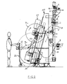
- the actual joining assembly is, in turn, constituted by a "Press" which, according to the invention, comprises a table or ramp pivoting (7), able to take two positions, one horizontal such that shown in Figures 1 and 2 allowing the establishment and positioning of the end (8) of the material (1) coming from the new roller (B2), and the other, in look of a vertical support surface (9) arranged transversely to the strip of material (1), behind the latter, in the area between the first return cylinder (3) and the cutting means (6).
- a Press which, according to the invention, comprises a table or ramp pivoting (7), able to take two positions, one horizontal such that shown in Figures 1 and 2 allowing the establishment and positioning of the end (8) of the material (1) coming from the new roller (B2), and the other, in look of a vertical support surface (9) arranged transversely to the strip of material (1), behind the latter, in the area between the first return cylinder (3) and the cutting means (6).
- the ramp or table (7) is advantageously a suction ramp which allows to maintain the end of the material (1) coming from the roller (R2). Possibly, the maintenance of the material could be ensured by other means equivalents, such as for example pinching.
- the operator When this end is positioned, the operator relates to its surface a double-sided adhesive strip or a fusible strip.
- this positioning of the material is produced by associating with the cylinder (4) a pressing assembly comprising a cylinder (10) capable of being rotated by a motor (11).
- the material (1) is pinched against the cylinder (4) by means of a cylinder bringing the cylinder (10) into contact with the cylinder (4). Just do turn the cylinder (10) so that the cut end is positioned opposite the bearing surface (9).
- the support surface (9) is associated with a heating pad.
- the set (7,9) is subject to pressure, pressure communicated for example by any means suitable, such as a hydraulic flange acting over the entire support length.
- these locking means can consist of two elements (13) in the form of stirrups which ensure the maintenance of the assembly (7.9) constituting the press.
- the exhausted roller (R1) on which the material has been returned cut located below the knife (6) is evacuated and the new roller (R2) is positioned for normal feeding.
- the operator can therefore bring a new roll and prepare a new one. connection phase.
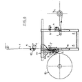
- Figure 2 illustrates in more detail the structure of a feed station of the material, equipped with a joining assembly according to the invention such that described previously and illustrated by figure 1.
- the vertical frame supporting all of the means constituting the joining station is mounted on a main frame (20) which supports the material supply roller (R1).
- the course of this roll is obtained by means of a motor (21). It could however be considered ensure the unrolling of the material by simple traction on the latter, the roller being then mounted free to rotate on a suitable support.
- Such an operation is carried out for example by means of a swivel assembly (22) controlled by a jack (23) which transfers the exhausted tube to an evacuation zone carried for example by the carriage (24) which ensures the positioning of the new roller (R2).
- this new roller (R2) is therefore brought by a operator by means of a carriage and, after joining operation, it is brought in drive position by the motor (21) by means of a lifting assembly (25) movable along the frame (20).
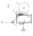
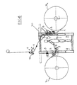
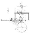
- Figures 3 to 9 illustrate a second embodiment of a installation according to the invention, showing all the phases of the splicing on such an installation.
- the installation according to the invention comprises two joining assemblies (A, B) arranged opposite one another and defining between them a work area for the operator.
- the material supply (1) is obtained from two rollers (R1, R2) arranged on each side of the vertical frames supporting the means of splicing.
- Such a design is particularly suitable when one is faced with joining operations close together, in particular in the case of heavy products, such as materials intended to produce articles molded or shaped which can weigh over one hundred grams per meter square, which therefore limits the length of the product stored in the form winding.
- each vertical frame supports a cylinder detour (3) for the material and the press assembly consists on the one hand by a suction table (7) for positioning the end (8) of the material supported by the roller intended to be substituted for that in process exhaustion, and, on the other hand, a transverse bearing surface (9).
- the positioning of the material in a vertical plane passing through the lower detour cylinder (3) and the bearing surface transverse (9), is obtained by means of a partially movable assembly high of the frame between the two workstations (A, B).
- This carriage-shaped assembly (30) comprises a detour roller (31), and also supports the cutting means (6) of the material taken from the roller (R1) being exhausted in order to be able to carry out the splicing operation proper.
- Such a cutting means is for example constituted by a pivoting knife, or by a paper cutter or any other equivalent cutting means.
- the material that feeds the installation of transformation comes from the roller (R1), the carriage (30) therefore being located on the side left of the installation.
- the operator prepares the primer (8) of the material (1) carried by the roller (R2) by positioning its end on the suction table (7) of the station (B).
- the table is tipped over support (7) which bears against the transverse bearing surface (9), which allows the joining operation to be carried out.
- a new roller (R1) can then be brought in ( Figure 6) and the operator can then proceed on the station (A) to the establishment of the end of the material of this roller for subsequent joining.
- Figure 9 illustrates a variant of an installation as described previously and illustrated by FIGS. 3 to 8.
- the pivoting table (7) has, at its end, on its entire length, a cylinder (40) mounted free to rotate.
- the transverse bearing surface (9) is also constituted by a idler cylinder mounted free in rotation and against which the cylinder (40) of the table.
- the cutting means are formed by a cutter, and in a manner similar to the knife described and illustrated by figures 1 and 2.
- such structure has the advantage of allowing the sticky element to be laminated and a restart of the line even before returning the swivel table to position horizontal to make a new preparation. This therefore results in a gain of time.
- the table or swivel ramp can be associated with means allowing its realignment of automatically with the end of the new material roll.
- the process according to the invention and the facilities which allow its implementation have the advantage that the joining operation can be carried out automatically, without stopping the line safe for operators.
Landscapes
- Replacement Of Web Rolls (AREA)
- Treatment Of Fiber Materials (AREA)
- Lining Or Joining Of Plastics Or The Like (AREA)
- Load-Engaging Elements For Cranes (AREA)
Abstract
Description
- on réalise une zone de réserve de matière entre le poste d'alimentation et la ligne de transformation d'une longueur permettant le fonctionnement de cette dernière pendant la durée de phase de raboutage ;
- la matière alimentant l'installation de transformation est déplacée verticalement entre deux éléments de guidage montés sur un bâti vertical disposé entre le rouleau d'alimentation et une zone de travail pour un opérateur ;
- l'extrémité du nouveau rouleau de matière est positionnée sur une première surface d'appui horizontale dite « rampe aspirante », l'opérateur disposé dans la zone de travail la recouvrant, sur toute sa largeur, d'une bande d'un élément de jonction (adhésif double face, ruban thermocollant) ;
- lorsque la bobine d'alimentation de l'installation est sur le point d'arriver à épuisement, la matière est immobilisée dans la zone comprise entre les deux éléments de guidage, et est ensuite coupée transversalement ;
- l'extrémité coupée est alors positionnée verticalement en regard d'une seconde surface d'appui, s'étendant transversalement entre les éléments de guidage en dessous ou au dessus des moyens de découpe ;
- la rampe aspirante supportant l'extrémité de la matière portée par le nouveau rouleau, pivote pour venir dans une position verticale en regard de la surface d'appui transversal ;
- après positionnement, la rampe et la surface d'appui transversale sont pressées l'une contre l'autre, entraínant la solidarisation des deux extrémités de matière, ces extrémités étant superposées dans le prolongement l'une de l'autre ;
- après solidarisation et écartement de la rampe aspirante, le freinage de la matière est éliminé, l'alimentation à l'installation de transformation redevenant de manière normale.
- un bâti vertical à l'extérieur duquel est disposée la source d'alimentation en matière, et dont l'autre face constitue un poste de travail pour l'opérateur, ledit bâti supportant deux éléments de guidage (cylindres), espacés l'un de l'autre, et définissant un passage vertical pour la matière en regard de la zone de travail ;
- des moyens de raboutage proprement dits montés sur ledit bâti vertical
et comprenant :
- des moyens d'arrêt de l'alimentation en matière et d'immobilisation de cette dernière dans le plan vertical compris entre les deux éléments de guidage ;
- un ensemble de découpe, positionné en partie haute du bâti, immédiatement en amont des moyens des moyens de blocage de la matière ;
- une presse comprenant une table pivotante entre deux positions, l'une horizontale à l'intérieur de la zone constituant le poste de travail pour l'opérateur, permettant la mise en place et le positionnement de l'extrémité du nouveau rouleau de matière et la mise en place d'un élément de jonction (adhésif double face, ruban thermocollant), et l'autre, en regard d'une surface d'appui disposée transversalement à l'arrière de la bande de matière entre le premier élément de guidage et les organes de coupe ;
- des moyens permettant éventuellement de ramener l'extrémité coupée de la matière alimentant la ligne de traitement au niveau de la surface d'appui transversale ;
- des moyens permettant de faire pivoter la table supportant l'extrémité du nouveau rouleau pour l'amener en regard de la surface d'appui transversale ;
- des moyens presseurs appliquant la table pivotante et la surface d'appui fixe l'une contre l'autre pour réaliser la liaison entre les deux extrémités.
- les figures 1 et 2 sont des vues de côté d'un poste de raboutage réalisé conformément à l'invention illustrant la manière dont est effectuée l'opération de raboutage et le remplacement d'une bobine vide par une bobine pleine ;
- les figures 3 à 8 illustrent une seconde forme de réalisation de l'installation conforme à l'invention, et montrent l'ensemble des phases du cycle de raboutage sur une telle installation ;
- la figure 9 illustre, en élévation, une variante d'une installation telle qu'illustrée par les figures 3 à 8, variante portant plus spécifiquement sur la structure des surfaces d'appui et des organes de découpe.
Claims (5)
- Procédé de raboutage entre un matériau en bande prélevé sur un rouleau (R1) et alimentant une ligne de transformation dudit matériau (1) et l'amorce (8) d'un second rouleau (R2) destiné à poursuivre l'alimentation après épuisement du premier sans arrêt de ladite ligne de transformation, caractérisé en ce que :on réalise une zone de réserve de matière entre le poste d'alimentation et la ligne de transformation d'une longueur permettant le fonctionnement de cette dernière pendant la durée de phase de raboutage ;la matière (1) alimentant l'installation de transformation est déplacée verticalement entre deux éléments de guidage (3,4) montés sur un bâti vertical disposé entre le rouleau d'alimentation (R1) et une zone de travail pour un opérateur ;l'extrémité (8) du nouveau rouleau (R2) de matière est positionnée sur une première surface d'appui (7) horizontale dite « rampe aspirante », l'opérateur disposé dans la zone de travail la recouvrant, sur toute sa largeur, d'une bande d'un élément de jonction (adhésif double face, ruban thermocollant) ;lorsque la bobine d'alimentation (R1) de l'installation est sur le point d'arriver à épuisement, la matière (1) est immobilisée dans la zone comprise entre les deux éléments de guidage (3,4), et est ensuite coupée transversalement ;l'extrémité coupée est alors positionnée verticalement en regard d'une seconde surface d'appui (9), s'étendant transversalement entre les éléments de guidage en dessous ou au dessus des moyens de découpe ;la rampe aspirante (7) supportant l'extrémité de la matière portée par le nouveau rouleau, pivote pour venir dans une position verticale en regard de la surface d'appui transversal (9) ;après positionnement, la rampe (7) et la surface d'appui transversale (9) sont pressées l'une contre l'autre, entraínant la solidarisation des deux extrémités de matière, ces extrémités étant superposées dans le prolongement l'une de l'autre ;après solidarisation et écartement de la rampe aspirante (7), le freinage de la matière est éliminé, l'alimentation à l'installation de transformation redevenant normale.
- Installation pour la mise en oeuvre du procédé selon la revendication 1, comportant, disposé entre un poste d'alimentation d'un rouleau de matière et une ligne de transformation de ladite matière, un poste de raboutage (2) permettant de réaliser la jonction avec l'amorce (8) de la matihre portée par un nouveau rouleau (R2) lors de l'épuisement du premier rouleau (R1), ledit ensemble de raboutage comprenant :un bâti vertical à l'extérieur duquel est disposée la source d'alimentation en matière, et dont l'autre face constitue un poste de travail pour l'opérateur, ledit bâti supportant deux éléments de guidage (3,4) (cylindres), espacés l'un de l'autre, et définissant un passage vertical pour la matière (1) en regard de la zone de travail ;des moyens de raboutage proprement dits montés sur ledit bâti vertical et comprenant :des moyens d'arrêt (5) de l'alimentation en matière (1) et d'immobilisation de cette dernière dans le plan vertical compris entre les deux éléments de guidage (3,4);un ensemble de découpe (6), positionné en partie haute du bâti, immédiatement en amont des moyens des moyens de blocage (5) de la matière ;une presse comprenant une table ou rampe pivotante (7) entre deux positions, l'une horizontale à l'intérieur de la zone constituant le poste de travail pour l'opérateur, permettant la mise en place et le positionnement de l'extrémité (8) du nouveau rouleau de matière et la mise en place d'un élément de jonction (adhésif double face, ruban thermocollant), et l'autre, en regard d'une surface d'appui (9) verticale disposée transversalement à l'arrière de la bande de matière entre le premier élément de guidage (3) et les organes de coupe (6) ;des moyens pour ramener éventuellement l'extrémité coupée de la matière alimentant la ligne de traitement au niveau de la surface d'appui transversale ;des moyens permettant de faire pivoter la table (7) supportant l'extrémité (8) du nouveau rouleau pour l'amener en regard de la surface d'appui transversale (9) ;des moyens presseurs appliquant la table pivotante (7) et la surface d'appui fixe (9) l'une contre l'autre pour réaliser la liaison entre les deux extrémités.
- Installation selon la revendication 2, caractérisée en ce le poste d'alimentation des rouleaux (R1,R2) est disposé, si l'on considère la position de l'opérateur par rapport au bâti vertical supportant les moyens de raboutage, à l'arrière de l'ensemble de raboutage, ledit poste d'alimentation comportant des moyens permettant d'enlever automatiquement le rouleau vide et de lui substituer le nouveau rouleau plein.
- Installation selon la revendication 2, caractérisée en ce qu'elle comporte deux ensembles de raboutage, espacés l'un de l'autre, et qui définissent entre eux une zone de travail pour l'opérateur, chaque bâti vertical supportant le cylindre de détour inférieur (3) ainsi qu'une presse comprenant la surface d'appui (table) (7) pivotante entre deux positions et la surface d'appui transversale (9) desdits ensembles de raboutage, le positionnement de la matière (1) dans un plan vertical passant par le cylindre de détour inférieur (3) et la surface d'appui transversale (7), étant obtenu par l'intermédiaire d'un ensemble (chariot) (30) déplaçable en partie haute du bâti entre les deux postes de travail (A,B), ledit ensemble (30) comportant un élément de détour (31) et le moyen de coupe (6) de la matière prélevée sur le rouleau en voie d'épuisement afin de pouvoir réaliser l'opération de raboutage proprement dite.
- / Installation selon la revendication 4, caractérisée en ce l'alimentation en matière (1) est obtenue directement à partir de rouleaux (R1, R2) disposés de chaque côté des bâtis verticaux.
Applications Claiming Priority (2)
| Application Number | Priority Date | Filing Date | Title |
|---|---|---|---|
| FR9910101A FR2796929B1 (fr) | 1999-07-30 | 1999-07-30 | Procede et installation pour rabouter les extremites de materiaux en bandes, articles textiles notamment |
| FR9910101 | 1999-07-30 |
Publications (2)
| Publication Number | Publication Date |
|---|---|
| EP1074497A1 true EP1074497A1 (fr) | 2001-02-07 |
| EP1074497B1 EP1074497B1 (fr) | 2004-02-25 |
Family
ID=9548865
Family Applications (1)
| Application Number | Title | Priority Date | Filing Date |
|---|---|---|---|
| EP00420160A Expired - Lifetime EP1074497B1 (fr) | 1999-07-30 | 2000-07-19 | Procédé et installation pour rabouter les extrémités de materiaux en bandes, bandes textiles notamment |
Country Status (5)
| Country | Link |
|---|---|
| EP (1) | EP1074497B1 (fr) |
| AT (1) | ATE260214T1 (fr) |
| DE (1) | DE60008463T2 (fr) |
| ES (1) | ES2215594T3 (fr) |
| FR (1) | FR2796929B1 (fr) |
Cited By (2)
| Publication number | Priority date | Publication date | Assignee | Title |
|---|---|---|---|---|
| ES2257205A1 (es) * | 2003-11-27 | 2006-07-16 | Tna Australia Pty Limited | Maquina empalmadora de material laminar. |
| CN1328138C (zh) * | 2002-08-21 | 2007-07-25 | 株式会社瑞光 | 带材的连接方法 |
Citations (6)
| Publication number | Priority date | Publication date | Assignee | Title |
|---|---|---|---|---|
| US1724225A (en) * | 1926-03-25 | 1929-08-13 | Scott Isabella | Roll-change device |
| US2035682A (en) * | 1933-08-31 | 1936-03-31 | Us Rubber Co | Apparatus for splicing strip material |
| US3276710A (en) * | 1964-10-30 | 1966-10-04 | Zerand Corp | Means and method for forming a butt splice in a running web |
| US4106974A (en) * | 1976-09-13 | 1978-08-15 | Curt G. Joa, Inc. | Flying splice apparatus |
| JPS59207351A (ja) * | 1983-05-06 | 1984-11-24 | Tokyo Kikai Seisakusho:Kk | 宛名印刷機の紙継装置 |
| US4629531A (en) * | 1983-12-28 | 1986-12-16 | Hiroshi Kataoka | Apparatus for joining sheet ends |
-
1999
- 1999-07-30 FR FR9910101A patent/FR2796929B1/fr not_active Expired - Fee Related
-
2000
- 2000-07-19 DE DE60008463T patent/DE60008463T2/de not_active Expired - Fee Related
- 2000-07-19 ES ES00420160T patent/ES2215594T3/es not_active Expired - Lifetime
- 2000-07-19 EP EP00420160A patent/EP1074497B1/fr not_active Expired - Lifetime
- 2000-07-19 AT AT00420160T patent/ATE260214T1/de not_active IP Right Cessation
Patent Citations (6)
| Publication number | Priority date | Publication date | Assignee | Title |
|---|---|---|---|---|
| US1724225A (en) * | 1926-03-25 | 1929-08-13 | Scott Isabella | Roll-change device |
| US2035682A (en) * | 1933-08-31 | 1936-03-31 | Us Rubber Co | Apparatus for splicing strip material |
| US3276710A (en) * | 1964-10-30 | 1966-10-04 | Zerand Corp | Means and method for forming a butt splice in a running web |
| US4106974A (en) * | 1976-09-13 | 1978-08-15 | Curt G. Joa, Inc. | Flying splice apparatus |
| JPS59207351A (ja) * | 1983-05-06 | 1984-11-24 | Tokyo Kikai Seisakusho:Kk | 宛名印刷機の紙継装置 |
| US4629531A (en) * | 1983-12-28 | 1986-12-16 | Hiroshi Kataoka | Apparatus for joining sheet ends |
Non-Patent Citations (1)
| Title |
|---|
| PATENT ABSTRACTS OF JAPAN vol. 009, no. 077 (M - 369) 6 April 1985 (1985-04-06) * |
Cited By (4)
| Publication number | Priority date | Publication date | Assignee | Title |
|---|---|---|---|---|
| CN1328138C (zh) * | 2002-08-21 | 2007-07-25 | 株式会社瑞光 | 带材的连接方法 |
| ES2257205A1 (es) * | 2003-11-27 | 2006-07-16 | Tna Australia Pty Limited | Maquina empalmadora de material laminar. |
| ES2257205B1 (es) * | 2003-11-27 | 2007-05-01 | Tna Australia Pty Limited | Maquina empalmadora de material laminar. |
| US7383867B2 (en) | 2003-11-27 | 2008-06-10 | Tna Australia Pty Limited | Film splicing machine |
Also Published As
| Publication number | Publication date |
|---|---|
| FR2796929B1 (fr) | 2001-09-21 |
| EP1074497B1 (fr) | 2004-02-25 |
| ES2215594T3 (es) | 2004-10-16 |
| ATE260214T1 (de) | 2004-03-15 |
| DE60008463D1 (de) | 2004-04-01 |
| DE60008463T2 (de) | 2004-12-16 |
| FR2796929A1 (fr) | 2001-02-02 |
Similar Documents
| Publication | Publication Date | Title |
|---|---|---|
| EP3248920B1 (fr) | Procédé de coupe et de raccordement de deux bandes bout à bout et à l arrêt dans une machine à dérouler, dispositif de coupe et de raccordement et machine équipée d'un tel dispositif permettant la mise en oeuvre dudit procédé | |
| EP1045746A1 (fr) | Coupe automatique de pieces dans une matiere en feuille | |
| EP3277486A1 (fr) | Tête d'application de fibres avec rouleau d'application particulier | |
| EP2112106B1 (fr) | Procédé et dispositif de coupe et de collage bout à bout pour machine à dérouler | |
| EP3248765A2 (fr) | Tête de depose d'un ruban de fibres impregnees, et dispositif de placement d'un tel ruban | |
| CA1311672C (fr) | Procede de fabrication de verre feuillete | |
| FR2552407A1 (fr) | Machine a raccorder des feuilles pour machine d'impression, de laminage ou de revetement | |
| EP1074497B1 (fr) | Procédé et installation pour rabouter les extrémités de materiaux en bandes, bandes textiles notamment | |
| EP3087020B1 (fr) | Procede de raboutage de deux articles thermofusibles sous forme de bandes ou de nappes, et module de raboutage pour la mise en oeuvre dudit procede | |
| EP0038277B1 (fr) | Machine pour le formage de profilé tubulaire | |
| EP0921074B1 (fr) | Procédé et installation pour rassembler des articles alignés au moyen de bandes adhésives | |
| EP3583060B1 (fr) | Procede et installation d'enroulage en continu de bandelettes de gomme pour former des galettes | |
| EP0943723A1 (fr) | Dispositif de prélèvement d'échantillon sur un produit en bande ou en feuille | |
| EP3980250B1 (fr) | Procédé et machine de scellage | |
| EP4448427A1 (fr) | Procede de raboutage de deux articles souples, et module de raboutage pour la mise en oeuvre dudit procede | |
| FR2692566A3 (fr) | Dispositif de jonction automatique des extrémités de deux nappes de matière. | |
| EP0658087B1 (fr) | Installation de decoupe de materiaux en feuille | |
| EP0252844B1 (fr) | Machine automatique pour le traitement d'un matériau en bande et notamment pour la découpe d'un tel matériau | |
| EP3038963B1 (fr) | Procede de raboutage de deux articles thermofusibles sous forme de bandes ou de nappes, et module de raboutage pour la mise en oeuvre dudit procede | |
| FR2989668A1 (fr) | Table d'injection de film pour fardeleuse | |
| BE883828A (fr) | Procede de fabrication de sacs, machine pour la mise en oeuvre de ce procede et sacs obtenus. | |
| EP4330006A1 (fr) | Procédé et installation perfectionnés d'enroulage en continu de bandelettes de gomme pour former des galettes | |
| WO2016142602A1 (fr) | Procédé de laminage perfectionne par ultrasons d'un article thermofusible, et dispositif de laminage pour la mise en œuvre dudit procédé | |
| WO1998004487A1 (fr) | Installation permettant de reconditionner sous la forme d'un enroulement une matiere en bande, telle qu'une etoffe | |
| FR2723361A1 (fr) | Dispositif de coupe et d'application, sans colle, du debut de bande d'une nouvelle bobine sur un mandrin d'un enrouleur |
Legal Events
| Date | Code | Title | Description |
|---|---|---|---|
| PUAI | Public reference made under article 153(3) epc to a published international application that has entered the european phase |
Free format text: ORIGINAL CODE: 0009012 |
|
| AK | Designated contracting states |
Kind code of ref document: A1 Designated state(s): AT BE CH CY DE DK ES FI FR GB GR IE IT LI LU MC NL PT SE |
|
| AX | Request for extension of the european patent |
Free format text: AL;LT;LV;MK;RO;SI |
|
| 17P | Request for examination filed |
Effective date: 20010316 |
|
| AKX | Designation fees paid |
Free format text: AT BE CH CY DE DK ES FI FR GB GR IE IT LI LU MC NL PT SE |
|
| 17Q | First examination report despatched |
Effective date: 20020904 |
|
| GRAP | Despatch of communication of intention to grant a patent |
Free format text: ORIGINAL CODE: EPIDOSNIGR1 |
|
| GRAS | Grant fee paid |
Free format text: ORIGINAL CODE: EPIDOSNIGR3 |
|
| GRAA | (expected) grant |
Free format text: ORIGINAL CODE: 0009210 |
|
| AK | Designated contracting states |
Kind code of ref document: B1 Designated state(s): AT BE CH CY DE DK ES FI FR GB GR IE IT LI LU MC NL PT SE |
|
| PG25 | Lapsed in a contracting state [announced via postgrant information from national office to epo] |
Ref country code: AT Free format text: LAPSE BECAUSE OF FAILURE TO SUBMIT A TRANSLATION OF THE DESCRIPTION OR TO PAY THE FEE WITHIN THE PRESCRIBED TIME-LIMIT Effective date: 20040225 Ref country code: IE Free format text: LAPSE BECAUSE OF FAILURE TO SUBMIT A TRANSLATION OF THE DESCRIPTION OR TO PAY THE FEE WITHIN THE PRESCRIBED TIME-LIMIT Effective date: 20040225 Ref country code: CY Free format text: LAPSE BECAUSE OF FAILURE TO SUBMIT A TRANSLATION OF THE DESCRIPTION OR TO PAY THE FEE WITHIN THE PRESCRIBED TIME-LIMIT Effective date: 20040225 Ref country code: FI Free format text: LAPSE BECAUSE OF FAILURE TO SUBMIT A TRANSLATION OF THE DESCRIPTION OR TO PAY THE FEE WITHIN THE PRESCRIBED TIME-LIMIT Effective date: 20040225 |
|
| REG | Reference to a national code |
Ref country code: GB Ref legal event code: FG4D Free format text: NOT ENGLISH |
|
| REG | Reference to a national code |
Ref country code: CH Ref legal event code: EP |
|
| REG | Reference to a national code |
Ref country code: IE Ref legal event code: FG4D Free format text: FRENCH |
|
| REF | Corresponds to: |
Ref document number: 60008463 Country of ref document: DE Date of ref document: 20040401 Kind code of ref document: P |
|
| PG25 | Lapsed in a contracting state [announced via postgrant information from national office to epo] |
Ref country code: DK Free format text: LAPSE BECAUSE OF FAILURE TO SUBMIT A TRANSLATION OF THE DESCRIPTION OR TO PAY THE FEE WITHIN THE PRESCRIBED TIME-LIMIT Effective date: 20040525 Ref country code: GR Free format text: LAPSE BECAUSE OF FAILURE TO SUBMIT A TRANSLATION OF THE DESCRIPTION OR TO PAY THE FEE WITHIN THE PRESCRIBED TIME-LIMIT Effective date: 20040525 Ref country code: SE Free format text: LAPSE BECAUSE OF FAILURE TO SUBMIT A TRANSLATION OF THE DESCRIPTION OR TO PAY THE FEE WITHIN THE PRESCRIBED TIME-LIMIT Effective date: 20040525 |
|
| GBT | Gb: translation of ep patent filed (gb section 77(6)(a)/1977) |
Effective date: 20040623 |
|
| PG25 | Lapsed in a contracting state [announced via postgrant information from national office to epo] |
Ref country code: LU Free format text: LAPSE BECAUSE OF NON-PAYMENT OF DUE FEES Effective date: 20040719 |
|
| PG25 | Lapsed in a contracting state [announced via postgrant information from national office to epo] |
Ref country code: LI Free format text: LAPSE BECAUSE OF NON-PAYMENT OF DUE FEES Effective date: 20040731 Ref country code: CH Free format text: LAPSE BECAUSE OF NON-PAYMENT OF DUE FEES Effective date: 20040731 Ref country code: MC Free format text: LAPSE BECAUSE OF NON-PAYMENT OF DUE FEES Effective date: 20040731 |
|
| REG | Reference to a national code |
Ref country code: IE Ref legal event code: FD4D |
|
| REG | Reference to a national code |
Ref country code: ES Ref legal event code: FG2A Ref document number: 2215594 Country of ref document: ES Kind code of ref document: T3 |
|
| PLBE | No opposition filed within time limit |
Free format text: ORIGINAL CODE: 0009261 |
|
| STAA | Information on the status of an ep patent application or granted ep patent |
Free format text: STATUS: NO OPPOSITION FILED WITHIN TIME LIMIT |
|
| 26N | No opposition filed |
Effective date: 20041126 |
|
| REG | Reference to a national code |
Ref country code: CH Ref legal event code: PL |
|
| PG25 | Lapsed in a contracting state [announced via postgrant information from national office to epo] |
Ref country code: FR Free format text: LAPSE BECAUSE OF NON-PAYMENT OF DUE FEES Effective date: 20050331 |
|
| REG | Reference to a national code |
Ref country code: FR Ref legal event code: ST |
|
| PGFP | Annual fee paid to national office [announced via postgrant information from national office to epo] |
Ref country code: NL Payment date: 20050623 Year of fee payment: 6 |
|
| PGFP | Annual fee paid to national office [announced via postgrant information from national office to epo] |
Ref country code: GB Payment date: 20050705 Year of fee payment: 6 |
|
| PGFP | Annual fee paid to national office [announced via postgrant information from national office to epo] |
Ref country code: ES Payment date: 20060717 Year of fee payment: 7 |
|
| PG25 | Lapsed in a contracting state [announced via postgrant information from national office to epo] |
Ref country code: GB Free format text: LAPSE BECAUSE OF NON-PAYMENT OF DUE FEES Effective date: 20060719 |
|
| PG25 | Lapsed in a contracting state [announced via postgrant information from national office to epo] |
Ref country code: NL Free format text: LAPSE BECAUSE OF NON-PAYMENT OF DUE FEES Effective date: 20070201 |
|
| GBPC | Gb: european patent ceased through non-payment of renewal fee |
Effective date: 20060719 |
|
| NLV4 | Nl: lapsed or anulled due to non-payment of the annual fee |
Effective date: 20070201 |
|
| PG25 | Lapsed in a contracting state [announced via postgrant information from national office to epo] |
Ref country code: PT Free format text: LAPSE BECAUSE OF NON-PAYMENT OF DUE FEES Effective date: 20040725 |
|
| REG | Reference to a national code |
Ref country code: ES Ref legal event code: FD2A Effective date: 20070720 |
|
| PGFP | Annual fee paid to national office [announced via postgrant information from national office to epo] |
Ref country code: DE Payment date: 20080715 Year of fee payment: 9 |
|
| PGFP | Annual fee paid to national office [announced via postgrant information from national office to epo] |
Ref country code: IT Payment date: 20080726 Year of fee payment: 9 |
|
| PG25 | Lapsed in a contracting state [announced via postgrant information from national office to epo] |
Ref country code: ES Free format text: LAPSE BECAUSE OF NON-PAYMENT OF DUE FEES Effective date: 20070720 |
|
| PGFP | Annual fee paid to national office [announced via postgrant information from national office to epo] |
Ref country code: BE Payment date: 20080814 Year of fee payment: 9 |
|
| BERE | Be: lapsed |
Owner name: S.A. *DMT CHOGNARD JEAN-LOUIS Effective date: 20090731 |
|
| PG25 | Lapsed in a contracting state [announced via postgrant information from national office to epo] |
Ref country code: BE Free format text: LAPSE BECAUSE OF NON-PAYMENT OF DUE FEES Effective date: 20090731 Ref country code: DE Free format text: LAPSE BECAUSE OF NON-PAYMENT OF DUE FEES Effective date: 20100202 |
|
| PG25 | Lapsed in a contracting state [announced via postgrant information from national office to epo] |
Ref country code: IT Free format text: LAPSE BECAUSE OF NON-PAYMENT OF DUE FEES Effective date: 20090719 |