EP1074432B1 - Mixed parallel and daisy chain bus architecture in a vehicle safety system - Google Patents
Mixed parallel and daisy chain bus architecture in a vehicle safety system Download PDFInfo
- Publication number
- EP1074432B1 EP1074432B1 EP00116876.4A EP00116876A EP1074432B1 EP 1074432 B1 EP1074432 B1 EP 1074432B1 EP 00116876 A EP00116876 A EP 00116876A EP 1074432 B1 EP1074432 B1 EP 1074432B1
- Authority
- EP
- European Patent Office
- Prior art keywords
- devices
- group
- protection
- daisy chain
- vehicle
- Prior art date
- Legal status (The legal status is an assumption and is not a legal conclusion. Google has not performed a legal analysis and makes no representation as to the accuracy of the status listed.)
- Expired - Lifetime
Links
- 238000011144 upstream manufacturing Methods 0.000 claims description 3
- 230000000452 restraining effect Effects 0.000 claims description 2
- 230000000712 assembly Effects 0.000 description 6
- 238000000429 assembly Methods 0.000 description 6
- 239000012530 fluid Substances 0.000 description 6
- 230000001953 sensory effect Effects 0.000 description 5
- 230000001133 acceleration Effects 0.000 description 4
- 230000008901 benefit Effects 0.000 description 3
- 210000003127 knee Anatomy 0.000 description 3
- 238000000034 method Methods 0.000 description 3
- 238000009434 installation Methods 0.000 description 2
- IJGRMHOSHXDMSA-UHFFFAOYSA-N Atomic nitrogen Chemical compound N#N IJGRMHOSHXDMSA-UHFFFAOYSA-N 0.000 description 1
- 239000004020 conductor Substances 0.000 description 1
- 230000001419 dependent effect Effects 0.000 description 1
- 238000001514 detection method Methods 0.000 description 1
- 229910001873 dinitrogen Inorganic materials 0.000 description 1
- 230000000694 effects Effects 0.000 description 1
- 239000000446 fuel Substances 0.000 description 1
- 230000036039 immunity Effects 0.000 description 1
- 239000000463 material Substances 0.000 description 1
- 238000002604 ultrasonography Methods 0.000 description 1
Images


Classifications
-
- B—PERFORMING OPERATIONS; TRANSPORTING
- B60—VEHICLES IN GENERAL
- B60R—VEHICLES, VEHICLE FITTINGS, OR VEHICLE PARTS, NOT OTHERWISE PROVIDED FOR
- B60R16/00—Electric or fluid circuits specially adapted for vehicles and not otherwise provided for; Arrangement of elements of electric or fluid circuits specially adapted for vehicles and not otherwise provided for
- B60R16/02—Electric or fluid circuits specially adapted for vehicles and not otherwise provided for; Arrangement of elements of electric or fluid circuits specially adapted for vehicles and not otherwise provided for electric constitutive elements
- B60R16/03—Electric or fluid circuits specially adapted for vehicles and not otherwise provided for; Arrangement of elements of electric or fluid circuits specially adapted for vehicles and not otherwise provided for electric constitutive elements for supply of electrical power to vehicle subsystems or for
- B60R16/0315—Electric or fluid circuits specially adapted for vehicles and not otherwise provided for; Arrangement of elements of electric or fluid circuits specially adapted for vehicles and not otherwise provided for electric constitutive elements for supply of electrical power to vehicle subsystems or for using multiplexing techniques
Definitions
- the present invention is generally directed to a vehicle safety system, such as an occupant protection system, that has a central control unit and a plurality of remote devices.
- the present invention is particularly directed to a system with an architecture that can minimize potential communication interruptions.
- the protection system includes one or more sensor devices for sensing vehicle characteristics and/or occupant characteristics. The sensed characteristics are used to determine whether a vehicle occupant needs to be protected (e.g., restrained) and/or determine a deployment profile of a device that accomplishes a protection function. Examples of the sensor devices include a vehicle acceleration sensor, an occupant position sensor, and an occupant weight sensor.
- the system includes one or more actuatable protection devices for protecting (e.g., restraining) the occupant.
- actuatable protection devices for protecting (e.g., restraining) the occupant.
- protection devices include an air bag module, a knee bolster module, and a seat belt pretensioner module.
- bus architecture is used for conveyance of communication signals.
- bus communication may be interrupted by such occurrences as crushing during a vehicle collision and associated deployment actuation of the protection devices within the system during the collision.
- daisy chain topology One type of protection system that has been developed utilizing centralized control and communication via a bus is a daisy chain topology system.
- the daisy chain system at least one conductor of the communication bus extends through each successive device.
- Daisy chain topology has an advantage in that individual remote devices (e.g., sensor and protection devices) can be installed into the associated vehicle in a non-programmed state (e.g., unaddressed). Once the devices are installed, a central control unit (CCU) programs each device via sequential polling or the like. Thus, it is desirable to maintain an ability to have a CCU program devices.
- CCU central control unit
- US 5 835 873 A discloses a vehicle safety system having a plurality of safety device controllers and a method of controlling same.
- the vehicle safety system provides for the protection of vehicle occupants in the event of a vehicle crash.
- the system is capable of controlling safety devices such as airbag assemblies, seat belt tensioner assemblies, fuel cutoff switch assemblies, battery disconnect switch assemblies, assemblies for sending notification to emergency services, and assemblies for sending vehicle location data.
- the system accepts data from other vehicle systems such as speed data from the antilock brake system to distinguish between a low speed and a high speed crash, seat occupancy data to selectively activate airbags, and steering system and acceleration data to detect vehicle rollover conditions.
- the system provides for fault detection and notification to the vehicle operator, as well as immunity from electromagnetic interference through the use of distributed controllers that communicate with a central electronic control unit over digital communication bus using coded commands and data. Each controller has the capability of performing self-tests and communicating the results to the central electronic control unit.
- a distributed vehicle safety system is provided as set forth in claim 1. Preferred embodiments of the present invention may be gathered from the dependent claims.
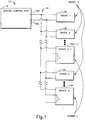
- FIG. 1 A representation of the present invention is schematically shown in Fig. 1 as a distributed safety system 10.
- the system 10 includes a central control unit (hereinafter "CCU") 12 and a plurality (e.g., N) of remotely located devices 14.
- the plurality of devices 14 may be any combination of safety system devices, and are thus illustrated via generic blocks in Fig. 1 .
- a control interconnection 16 extends from the CCU 12 to the plurality of devices 14. Electrical communication signals, and preferably electrical energy for power, pass between the CCU 12 and the devices 14 via the control interconnection 16.
- the control interconnection 16 preferably is comprised of two electrically conductive connector lines 18A and 18B, and is hereinafter referred to as the bus 16.
- the system 10 is a vehicle occupant protection system for helping to protect an occupant (not shown) of a vehicle (not shown).
- the devices 14 are hereinafter generically referred to as protection system devices 14. Some of the protection system devices 14 are actuatable to help protect (e.g., restrain) the occupant, and some of the devices are used to determine control (e.g., actuation) of the actuatable protection devices.
- actuatable protection devices examples include an air bag module, a knee bolster module, a seat belt lock, a seat belt pretensioner module, and a D-ring adjuster module.
- actuatable protection devices may also have adjustable actuation variable(s). Such adjustable variables include deployment timing, air bag dynamic profile, pressure, etc.
- each air bag module includes an associated inflatable restraint 22, commonly referred to as an air bag.
- the air bag 22 is stored in a folded condition within the module in a manner well known in the art.
- a source 24 of inflation fluid e.g., nitrogen gas
- the source 24 of inflation fluid is commonly referred to as an inflator, and includes a stored quantity of pressurized inflation fluid and/or an inflation fluid generating material.
- the inflator 24 has an associated igniter (e.g., a pyrotechnic squib), which is electrically activated to initiate flow of the inflation fluid from the inflator.
- igniter e.g., a pyrotechnic squib
- the flow of inflation fluid to the air bag 22 inflates the air bag, as will be appreciated by a person of ordinary skill in the art.
- the protection system devices 14 that are involved in the determination of control (e.g., actuation) of the actuatable protection devices include sensor devices. Each sensor device senses a characteristic that is used to determine whether the additional protection help (e.g., air bag restraint of occupant) is to be provided (e.g., actuation deployment of one or more of the actuatable protection devices) and/or how the additional protection help is to be provided (e.g., adjustment of deployment of one or more of the actuatable protection devices). Thus, the sensor devices perform a function associated with protection of a vehicle occupant.
- the additional protection help e.g., air bag restraint of occupant
- sensor devices include a vehicle crash sensor (e.g., an accelerometer), an occupant position sensor (e.g., an ultrasound or an infrared sensor), and an occupant weight sensor (e.g., a pressure sensor).
- vehicle crash sensor e.g., an accelerometer
- occupant position sensor e.g., an ultrasound or an infrared sensor
- occupant weight sensor e.g., a pressure sensor
- the example shown within Fig. 2 contains two protection system devices 14(N-1) and 14N that are sensor devices.
- the first sensor device 14(N-1) is an occupant characteristic sensor (e.g., an ultrasonic sensor) with an occupant characteristic sensor function 30
- the second sensor device 14N is a vehicle characteristic sensor (e.g., an accelerometer) with a vehicle characteristic sensor function 32.
- Each of the protection system devices 14 has control circuitry 34 for communication via the bus 16 and for control of function(s) at the respective device.
- the control circuitry e.g., 34A
- the control circuitry e.g., 34N
- protection system devices 14 of the illustrated example are individually identified herein via alphabetic suffixes and that the devices have some elements that are identified by numbers with corresponding alphabetic suffixes.
- alphabetic suffixes are sometimes omitted for generic discussions (i.e., applicable to all of the referenced numbered elements).
- the CCU 12 receives the sensory input from the sensor devices (e.g., 14N) and using the sensory input regarding the sensed characteristics makes determinations regarding protection device control.
- the CCU 12 analyzes the information derived from the sensed characteristics and determines if a deployment crash condition is occurring (e.g., the CCU performs a crash algorithm).
- a deployment crash condition is one in which deployment of one or more protection devices is desirable to hopefully, in combination with other vehicle systems (e.g., seat belts or the like), enhance protection of the occupant.
- the CCU 12 includes a microcomputer 36 to perform the analysis/determination function.
- the CCU 12 determines adjustment, and controls the adjustment of the deployment variable(s) accordingly.
- the receipt of the sensory signals, the provision of control signals, and the receipt/provision of other signals is via a communication portion 38 of the CCU 12 that is connected to the bus 16.
- the communication portion 38 is connected to the microcomputer 36 and other portion(s) (not shown) of the CCU 12.
- the communication portion 38 of the CCU 12 is connected to both a vehicle power source 40 (i.e., the vehicle battery) and to vehicle ground 42 for provision of electrical power for the plurality of protection system devices 14, via the bus 16.
- a vehicle power source 40 i.e., the vehicle battery
- vehicle ground 42 for provision of electrical power for the plurality of protection system devices 14, via the bus 16.
- Any known method of providing electrical power and communication signals over the same electrical interconnection(s) can be employed within the system 10. Thus, the known methods of electrical power and communication signal provision are not discussed in detail herein.
- the bus 16 is connected to the protection system devices 14 via a combination of parallel connections and daisy chain connections. Specifically, a first portion (of number K, with K ⁇ N, and referred to herein as "subset K") of the protection system devices 14 are merely connected in parallel between the two connector lines 18A and 18B.
- a second portion (of number L, with L ⁇ N, and referred to herein as "subset L") of the protection system devices 14 have a daisy chain connection along one of the two connector lines (e.g., 18A). Each daisy chain connection entails connection of the connector line 18A through the respective device (e.g., 14N-1)). Each of the daisy chain devices (subset L) is also connected to the other connector line 18B.
- the two subsets K and L comprise the entire group of protection system devices.
- the number of protection system devices within any one subset is any number less than the total number of devices (i.e., less that N), with the other subset comprising the remainder.
- the devices of the two subsets K and L can occur in any order, and can even intermingle as shown in the example.
- the devices of one subset e.g., K
- the devices of the other subset e.g., L
- the connector lines are connected to each of the protection system devices (i.e., each of the devices in each of the subsets K and L).
- an electronic switch 46 is interposed along the connector line for each daisy-chained device.
- a switch e.g., 46(N-1)
- each protection system device e.g., 14(N-1)
- Each electronic switch 46 has an "ON” or "CLOSED” state, and an "OFF” or “OPENED” state. In its ON state each switch (e.g., 46(N-1)) permits electrical flow (e.g., signals and energy) through the switch, and in its OFF state each switch blocks/interrupts electrical flow.
- the switches 46 are shown within the respective protection system devices 14 of the subset L. A person of ordinary skill in the art will appreciate that the switches 46 can be separate from the respective protection system devices, and yet be associated with the respective device.
- Each switch (e.g., 46(N-1)) associated with a protection system device is interposed between the CCU 12 and all of the protection system devices 14, if any, that are "downstream" of the particular protection system device (e.g., 14(N-1)).
- the nomenclature "downstream" is with reference to a direction away from the CCU 12, and proceeding toward a last protection system device 14N connected on the bus 16.
- both of the connector lines 18A and 18B are connected to the control circuitry 34 of the respective device.
- the CCU 12 can communicate with, and supply power to, the control circuitry 34 of a respective protection system device so long as all of the upstream switches 46, if any, are closed.
- the control circuitry 34 controls the associated switch 46.
- Protection system devices 14 that are daisy chain connected can be non-programmed (e.g., unaddressed) upon installation into a vehicle. Specifically, if the protection system devices 14 in the subset L have open switches 46 until programmed, then the CCU 12 merely has to poll the protection system devices that are able to communicate to determine which device is non-programmed.
- the protection system devices 14 in the subset L have open switches 46.
- only one non-programmed protection system device (e.g., 14(N-1)) of the subset L can engage in communication (i.e., be polled and programmed) with the CCU 12 at a time (i.e., only the upstream-most device of the subset L can communicate because its associated switch 46 prevents the downstream devices from engaging in communication).
- its associated switch e.g., 46(N-1)
- communication can then reach downstream device(s) up to the next open switch (i.e., at the next one of the devices in the subset L).
- these protection system devices typically must be preprogrammed (i.e., pre-addressed) prior to installation.
- the CCU 12 can immediately communicate with the preprogrammed devices.
- Preprogramming is preferred because it is possible that a plurality of non-preprogrammed devices of the subset K would be capable of communicating with the CCU 12 (e.g., several non-preprogrammed devices located upstream of a first switch 46).
- preprogramming avoids the need for a special communication arbitration scheme that would allow the CCU to sequentially program such a plurality of devices.
- a benefit of the parallel connection topology (subset K) is that a communication-disrupting event at any of the protection system devices in the subset K does not effect communication to the rest of the protection system devices. For example, if the control circuitry (e.g., 34A) of one of the parallel-connected devices (e.g., 14A) is damaged such as upon actuation of the device, communication on the bus 16 is not interrupted because the control circuitry of the parallel-connected device is not involved with switch control (no switch is associated with the device).
- FIG. 3 An example of a system 50 within a vehicle 52 in accordance with the present invention is shown in Fig. 3 .
- a CCU 54 is provided to communicate via four communication interconnections ("buses") 56-62.
- the first bus 56 only communicates with a single device 64.
- the single device 64 is a passenger sensor for sensing a passenger (not shown).
- the second bus 58 provides communication for first and second passenger front air bag devices 66 and 68 (i.e., a torso bag and a knee bolster).
- the first and second passenger front air bag devices 66 and 68 are connected in parallel to the second bus 58.
- a passenger weight sensor 70 and a vehicle lateral acceleration sensor 72 are connected in daisy-chain configuration to the second bus 58.
- a passenger side air bag device 74 and a head air bag device 76 are connected in parallel to the second bus 58.
- frontal crush sensors 78 and 80 are connected in daisy-chain fashion to the second bus 58.
- the third bus 60 has two driver front air bag devices 82 and 84 that are connected in parallel.
- a driver sensor 86 i.e., a position sensor
- a vehicle lateral acceleration sensor 88 are connected in daisy-chain topology to the third bus 60.
- a side air bag device 90 and a head air bag device 92 are connected in parallel to the third bus 60.
- the fourth bus 62 provides for communication from the CCU 54 to seven seat belt pretensioners 94-106 (i.e., one associated with the driver seat and one associated with each of six passenger seats).
- the fourth bus 62 also serves two side air bag devices 108 and 110.
- the air bag devices 108 and 110 are associated with passenger seat locations in a second seating group (not shown) within the vehicle.
- the pretensioner devices 94-106 are all connected in daisy-chain topology.
- the side air bag devices 108 and 110 are connected in parallel topology.
Landscapes
- Engineering & Computer Science (AREA)
- Mechanical Engineering (AREA)
- Air Bags (AREA)
Description
- The present invention is generally directed to a vehicle safety system, such as an occupant protection system, that has a central control unit and a plurality of remote devices. The present invention is particularly directed to a system with an architecture that can minimize potential communication interruptions.
- One type of vehicle safety system is an occupant protection system. The protection system includes one or more sensor devices for sensing vehicle characteristics and/or occupant characteristics. The sensed characteristics are used to determine whether a vehicle occupant needs to be protected (e.g., restrained) and/or determine a deployment profile of a device that accomplishes a protection function. Examples of the sensor devices include a vehicle acceleration sensor, an occupant position sensor, and an occupant weight sensor.
- The system includes one or more actuatable protection devices for protecting (e.g., restraining) the occupant. Examples of such protection devices include an air bag module, a knee bolster module, and a seat belt pretensioner module.
- As the sophistication of occupant protection systems has increased, the number and complexity of the sensor and protection devices in a single vehicle has increased. In response to the increased number and complexity of devices, there has been a movement toward centralized control of the devices to reduce cost and to increase reliability of the overall protection system. In order to accomplish the centralized control, a bus architecture is used for conveyance of communication signals. A potential exists that bus communication may be interrupted by such occurrences as crushing during a vehicle collision and associated deployment actuation of the protection devices within the system during the collision.
- One type of protection system that has been developed utilizing centralized control and communication via a bus is a daisy chain topology system. Within the daisy chain system, at least one conductor of the communication bus extends through each successive device. Daisy chain topology has an advantage in that individual remote devices (e.g., sensor and protection devices) can be installed into the associated vehicle in a non-programmed state (e.g., unaddressed). Once the devices are installed, a central control unit (CCU) programs each device via sequential polling or the like. Thus, it is desirable to maintain an ability to have a CCU program devices.
-
US 5 835 873 A discloses a vehicle safety system having a plurality of safety device controllers and a method of controlling same. The vehicle safety system provides for the protection of vehicle occupants in the event of a vehicle crash. The system is capable of controlling safety devices such as airbag assemblies, seat belt tensioner assemblies, fuel cutoff switch assemblies, battery disconnect switch assemblies, assemblies for sending notification to emergency services, and assemblies for sending vehicle location data. The system accepts data from other vehicle systems such as speed data from the antilock brake system to distinguish between a low speed and a high speed crash, seat occupancy data to selectively activate airbags, and steering system and acceleration data to detect vehicle rollover conditions. The system provides for fault detection and notification to the vehicle operator, as well as immunity from electromagnetic interference through the use of distributed controllers that communicate with a central electronic control unit over digital communication bus using coded commands and data. Each controller has the capability of performing self-tests and communicating the results to the central electronic control unit. - In accordance with the present invention, a distributed vehicle safety system is provided as set forth in
claim 1. Preferred embodiments of the present invention may be gathered from the dependent claims. - The foregoing and other features and advantages of the present invention will become apparent to those skilled in the art to which the present invention relates upon reading the following description with reference to the accompanying drawings, wherein:
- Fig. 1
- is a schematic illustration of a system in accordance with the present invention;
- Fig. 2
- is a schematic illustration of the system shown in
Fig. 1 with example details shown for a central control unit and a select few remotelylocated devices within the system; and - Fig. 3
- is a schematic illustration of an example of a system in accordance with the present invention within an associated schematically shown vehicle.
- A representation of the present invention is schematically shown in
Fig. 1 as adistributed safety system 10. Thesystem 10 includes a central control unit (hereinafter "CCU") 12 and a plurality (e.g., N) of remotely locateddevices 14. The plurality ofdevices 14 may be any combination of safety system devices, and are thus illustrated via generic blocks inFig. 1 . - A
control interconnection 16 extends from theCCU 12 to the plurality ofdevices 14. Electrical communication signals, and preferably electrical energy for power, pass between theCCU 12 and thedevices 14 via thecontrol interconnection 16. Thecontrol interconnection 16 preferably is comprised of two electricallyconductive connector lines bus 16. - Preferably, the
system 10 is a vehicle occupant protection system for helping to protect an occupant (not shown) of a vehicle (not shown). Accordingly, thedevices 14 are hereinafter generically referred to asprotection system devices 14. Some of theprotection system devices 14 are actuatable to help protect (e.g., restrain) the occupant, and some of the devices are used to determine control (e.g., actuation) of the actuatable protection devices. - Examples of actuatable protection devices include an air bag module, a knee bolster module, a seat belt lock, a seat belt pretensioner module, and a D-ring adjuster module. A person of ordinary skill in the art will appreciate that the actuatable protection devices may also have adjustable actuation variable(s). Such adjustable variables include deployment timing, air bag dynamic profile, pressure, etc.
- For the purpose of illustration of the invention and not for the purpose of limitation, the specific example structure shown in
Fig. 2 hasoccupant protection devices - The
protection system devices 14 that are involved in the determination of control (e.g., actuation) of the actuatable protection devices include sensor devices. Each sensor device senses a characteristic that is used to determine whether the additional protection help (e.g., air bag restraint of occupant) is to be provided (e.g., actuation deployment of one or more of the actuatable protection devices) and/or how the additional protection help is to be provided (e.g., adjustment of deployment of one or more of the actuatable protection devices). Thus, the sensor devices perform a function associated with protection of a vehicle occupant. - Examples of sensor devices include a vehicle crash sensor (e.g., an accelerometer), an occupant position sensor (e.g., an ultrasound or an infrared sensor), and an occupant weight sensor (e.g., a pressure sensor). The example shown within
Fig. 2 contains two protection system devices 14(N-1) and 14N that are sensor devices. For the purpose of illustration only and not for the purpose of limitation, the first sensor device 14(N-1) is an occupant characteristic sensor (e.g., an ultrasonic sensor) with an occupantcharacteristic sensor function 30, and thesecond sensor device 14N is a vehicle characteristic sensor (e.g., an accelerometer) with a vehiclecharacteristic sensor function 32. - Each of the
protection system devices 14 hascontrol circuitry 34 for communication via thebus 16 and for control of function(s) at the respective device. For example, at the actuatable occupant protection devices (e.g., 14A), the control circuitry (e.g., 34A) receives actuation command communication from theCCU 12, and causes actuation. At the sensor devices (e.g., 14N), the control circuitry (e.g., 34N) assembles sensory information and provides communications that conveys the sensory information to theCCU 12. - It is to be appreciated that the
protection system devices 14 of the illustrated example are individually identified herein via alphabetic suffixes and that the devices have some elements that are identified by numbers with corresponding alphabetic suffixes. Herein, the alphabetic suffixes are sometimes omitted for generic discussions (i.e., applicable to all of the referenced numbered elements). - The
CCU 12 receives the sensory input from the sensor devices (e.g., 14N) and using the sensory input regarding the sensed characteristics makes determinations regarding protection device control. In one example, theCCU 12 analyzes the information derived from the sensed characteristics and determines if a deployment crash condition is occurring (e.g., the CCU performs a crash algorithm). A deployment crash condition is one in which deployment of one or more protection devices is desirable to hopefully, in combination with other vehicle systems (e.g., seat belts or the like), enhance protection of the occupant. Preferably, theCCU 12 includes amicrocomputer 36 to perform the analysis/determination function. Also, a person of ordinary skill in the art will appreciate that if the actuatable occupant protection devices (e.g., 14A) have adjustable aspects (adjustable to tailor deployment actuation of the respective protection device) theCCU 12 determines adjustment, and controls the adjustment of the deployment variable(s) accordingly. - At the
CCU 12, the receipt of the sensory signals, the provision of control signals, and the receipt/provision of other signals is via acommunication portion 38 of theCCU 12 that is connected to thebus 16. Thecommunication portion 38 is connected to themicrocomputer 36 and other portion(s) (not shown) of theCCU 12. Preferably, thecommunication portion 38 of theCCU 12 is connected to both a vehicle power source 40 (i.e., the vehicle battery) and tovehicle ground 42 for provision of electrical power for the plurality ofprotection system devices 14, via thebus 16. Any known method of providing electrical power and communication signals over the same electrical interconnection(s) can be employed within thesystem 10. Thus, the known methods of electrical power and communication signal provision are not discussed in detail herein. - In accordance with the present invention and as is schematically shown in the figures, the
bus 16 is connected to theprotection system devices 14 via a combination of parallel connections and daisy chain connections. Specifically, a first portion (of number K, with K<N, and referred to herein as "subset K") of theprotection system devices 14 are merely connected in parallel between the twoconnector lines - A second portion (of number L, with L<N, and referred to herein as "subset L") of the
protection system devices 14 have a daisy chain connection along one of the two connector lines (e.g., 18A). Each daisy chain connection entails connection of theconnector line 18A through the respective device (e.g., 14N-1)). Each of the daisy chain devices (subset L) is also connected to theother connector line 18B. - In the illustrated example, the two subsets K and L comprise the entire group of protection system devices. The number of protection system devices within any one subset is any number less than the total number of devices (i.e., less that N), with the other subset comprising the remainder. The devices of the two subsets K and L can occur in any order, and can even intermingle as shown in the example. Thus, the devices of one subset (e.g., K) are interspersed among the devices of the other subset (e.g., L) along the
bus 16. - Focusing now on the two
connector lines bus 16, the connector lines are connected to each of the protection system devices (i.e., each of the devices in each of the subsets K and L). For theconnector line 18A that is associated with the daisy chain topology, anelectronic switch 46 is interposed along the connector line for each daisy-chained device. In other words, a switch (e.g., 46(N-1)) on theconnector line 18A is associated with each protection system device (e.g., 14(N-1)) of the subset L. Eachelectronic switch 46 has an "ON" or "CLOSED" state, and an "OFF" or "OPENED" state. In its ON state each switch (e.g., 46(N-1)) permits electrical flow (e.g., signals and energy) through the switch, and in its OFF state each switch blocks/interrupts electrical flow. - In the illustrated embodiment, the
switches 46 are shown within the respectiveprotection system devices 14 of the subset L. A person of ordinary skill in the art will appreciate that theswitches 46 can be separate from the respective protection system devices, and yet be associated with the respective device. - Each switch (e.g., 46(N-1)) associated with a protection system device (e.g., 14(N-1)) is interposed between the
CCU 12 and all of theprotection system devices 14, if any, that are "downstream" of the particular protection system device (e.g., 14(N-1)). It should be appreciated that the nomenclature "downstream" is with reference to a direction away from theCCU 12, and proceeding toward a lastprotection system device 14N connected on thebus 16. Within each of theprotection system devices 14 of the subset L, both of theconnector lines control circuitry 34 of the respective device. Thus, theCCU 12 can communicate with, and supply power to, thecontrol circuitry 34 of a respective protection system device so long as all of theupstream switches 46, if any, are closed. In turn, thecontrol circuitry 34 controls the associatedswitch 46. -
Protection system devices 14 that are daisy chain connected (i.e., the subset L) can be non-programmed (e.g., unaddressed) upon installation into a vehicle. Specifically, if theprotection system devices 14 in the subset L haveopen switches 46 until programmed, then theCCU 12 merely has to poll the protection system devices that are able to communicate to determine which device is non-programmed. - Recall that until programmed, the
protection system devices 14 in the subset L haveopen switches 46. Thus, only one non-programmed protection system device (e.g., 14(N-1)) of the subset L can engage in communication (i.e., be polled and programmed) with theCCU 12 at a time (i.e., only the upstream-most device of the subset L can communicate because its associatedswitch 46 prevents the downstream devices from engaging in communication). When the programming of the one device (e.g., 14(N-1)) is complete, its associated switch (e.g., 46(N-1)) is closed and communication can then reach downstream device(s) up to the next open switch (i.e., at the next one of the devices in the subset L). - Turning to the subset K, these protection system devices (e.g., 14A and 14B) typically must be preprogrammed (i.e., pre-addressed) prior to installation. The
CCU 12 can immediately communicate with the preprogrammed devices. Preprogramming is preferred because it is possible that a plurality of non-preprogrammed devices of the subset K would be capable of communicating with the CCU 12 (e.g., several non-preprogrammed devices located upstream of a first switch 46). Thus, preprogramming avoids the need for a special communication arbitration scheme that would allow the CCU to sequentially program such a plurality of devices. - A benefit of the parallel connection topology (subset K) is that a communication-disrupting event at any of the protection system devices in the subset K does not effect communication to the rest of the protection system devices. For example, if the control circuitry (e.g., 34A) of one of the parallel-connected devices (e.g., 14A) is damaged such as upon actuation of the device, communication on the
bus 16 is not interrupted because the control circuitry of the parallel-connected device is not involved with switch control (no switch is associated with the device). - It should be appreciated that the present invention may be utilized in various forms and configurations. An example of a
system 50 within avehicle 52 in accordance with the present invention is shown inFig. 3 . Within thesystem 50 ofFig. 3 , aCCU 54 is provided to communicate via four communication interconnections ("buses") 56-62. Thefirst bus 56 only communicates with asingle device 64. Thesingle device 64 is a passenger sensor for sensing a passenger (not shown). - The
second bus 58 provides communication for first and second passenger frontair bag devices 66 and 68 (i.e., a torso bag and a knee bolster). The first and second passenger frontair bag devices second bus 58. Apassenger weight sensor 70 and a vehiclelateral acceleration sensor 72 are connected in daisy-chain configuration to thesecond bus 58. A passenger sideair bag device 74 and a headair bag device 76 are connected in parallel to thesecond bus 58. Two -
frontal crush sensors second bus 58. - The
third bus 60 has two driver frontair bag devices lateral acceleration sensor 88 are connected in daisy-chain topology to thethird bus 60. A sideair bag device 90 and a headair bag device 92 are connected in parallel to thethird bus 60. - The
fourth bus 62 provides for communication from theCCU 54 to seven seat belt pretensioners 94-106 (i.e., one associated with the driver seat and one associated with each of six passenger seats). Thefourth bus 62 also serves two sideair bag devices air bag devices air bag devices
Claims (4)
- A distributed vehicle safety system (10) comprising:a control unit (12);a plurality of devices (14), each for performing a function associated with protection of a vehicle occupant, the plurality of devices (14) including a first group of devices (K) and a second group of devices (L), the second group of devices (L) each having an associated daisy chain switch; anda control interconnection bus (16) for electrically connecting said control unit (12) to each said plurality of said devices (K, L), said control interconnection bus (16) including a first connector line (18A) and a second connector line (18B);said first group of said devices (K) being directly connected to both said first and said second connector lines (18A, 18B) so that said first group of devices (K) are connected in parallel to said control unit (12);said second group of said devices (L) being directly connected to said second connector line (18B), at least one of said second group of said devices (L) being connectable to said first connector line (18A) through a daisy chain switch associated with one of said second group of said devices arranged upstream of said at least one of said second group of said devices (L).
- The distributed vehicle safety system of claim 1 wherein said first group of devices (K) includes actuatable restraining devices (22A, 22B) and said second group of devices (L) includes programmable sensors (30, 32).
- The distributed vehicle safety system of claim 2 wherein said associated daisy chain switch of each of said second group of devices (L) closes when the associated device is programmed.
- The distributed vehicle safety system of claim 3 wherein said second group of devices (L) are connected in parallel to said control unit (12) when all of said daisy chain switches are closed.
Applications Claiming Priority (2)
| Application Number | Priority Date | Filing Date | Title |
|---|---|---|---|
| US09/369,109 US6212457B1 (en) | 1999-08-05 | 1999-08-05 | Mixed parallel and daisy chain bus architecture in a vehicle safety system |
| US369109 | 1999-08-05 |
Publications (2)
| Publication Number | Publication Date |
|---|---|
| EP1074432A1 EP1074432A1 (en) | 2001-02-07 |
| EP1074432B1 true EP1074432B1 (en) | 2019-11-20 |
Family
ID=23454128
Family Applications (1)
| Application Number | Title | Priority Date | Filing Date |
|---|---|---|---|
| EP00116876.4A Expired - Lifetime EP1074432B1 (en) | 1999-08-05 | 2000-08-04 | Mixed parallel and daisy chain bus architecture in a vehicle safety system |
Country Status (2)
| Country | Link |
|---|---|
| US (1) | US6212457B1 (en) |
| EP (1) | EP1074432B1 (en) |
Families Citing this family (27)
| Publication number | Priority date | Publication date | Assignee | Title |
|---|---|---|---|---|
| US6733036B2 (en) | 1995-06-07 | 2004-05-11 | Automotive Technologies International, Inc. | Automotive electronic safety network |
| US6905135B2 (en) | 1995-06-07 | 2005-06-14 | Automotive Technologies International, Inc. | Inflator system |
| US9443358B2 (en) | 1995-06-07 | 2016-09-13 | Automotive Vehicular Sciences LLC | Vehicle software upgrade techniques |
| US7832762B2 (en) * | 1995-06-07 | 2010-11-16 | Automotive Technologies International, Inc. | Vehicular bus including crash sensor or occupant protection system control module |
| US7527288B2 (en) * | 1995-06-07 | 2009-05-05 | Automotive Technologies International, Inc. | Vehicle with crash sensor coupled to data bus |
| US7580782B2 (en) * | 1995-10-30 | 2009-08-25 | Automotive Technologies International, Inc. | Vehicular electronic system with crash sensors and occupant protection systems |
| US7744122B2 (en) | 1995-12-12 | 2010-06-29 | Automotive Technologies International, Inc. | Driver side aspirated airbags |
| DE19813921A1 (en) * | 1998-03-28 | 1999-09-30 | Telefunken Microelectron | Method for operating a restraint system networked via a bus line in the event of a faulty power supply |
| US10240935B2 (en) | 1998-10-22 | 2019-03-26 | American Vehicular Sciences Llc | Vehicle software upgrade techniques |
| US6302439B1 (en) * | 2000-02-01 | 2001-10-16 | Trw Inc. | Distributed occupant protection system and method with cooperative central and distributed protection module actuation control |
| US6800957B2 (en) * | 2001-02-06 | 2004-10-05 | General Electric Company | Electronic distribution system for 36V automobiles |
| WO2002075464A1 (en) * | 2001-03-15 | 2002-09-26 | Robert Bosch Gmbh | Method for operating a distributed safety-relevant system |
| US6918458B2 (en) * | 2001-10-12 | 2005-07-19 | Autoliv Asp, Inc. | Load management system and method for motor vehicle restraints |
| DE10208690B4 (en) * | 2002-02-27 | 2007-04-12 | Man Nutzfahrzeuge Ag | Electronic system for a vehicle, in particular commercial vehicle |
| DE10225888B4 (en) * | 2002-06-11 | 2007-06-21 | Daimlerchrysler Ag | Modular chassis system |
| FR2841007B1 (en) * | 2002-06-18 | 2004-07-23 | Schneider Automation | SECURITY COMMUNICATION SYSTEM |
| DE10242051A1 (en) * | 2002-09-11 | 2004-03-25 | Adam Opel Ag | Data bus system for motor vehicle with several bus users has main bus user in series with other bus users to supply them with voltage via switch and controlling switch depending on control signal |
| US7191269B2 (en) * | 2003-07-30 | 2007-03-13 | Delphi Technologies, Inc. | Method for multiple sensors to communicate on a uni-directional bus |
| US7125045B2 (en) | 2003-11-26 | 2006-10-24 | Visteon Global Technologies, Inc. | Active knee bolster with adaptive force response system and method |
| DE102006026239B4 (en) * | 2005-06-07 | 2008-04-17 | Denso Corp., Kariya | Occupant protection apparatus and method for protecting an occupant |
| US20070067082A1 (en) * | 2005-09-20 | 2007-03-22 | Robert Bosch Gmbh | Integrated vehicle system |
| US20070198139A1 (en) * | 2006-02-21 | 2007-08-23 | Colm Boran | Auto-address multi-sensor network |
| DE102007059438B4 (en) * | 2007-12-10 | 2018-05-30 | Volkswagen Ag | Method for transferring data between control devices in a vehicle |
| US8842026B2 (en) | 2012-12-05 | 2014-09-23 | Infineon Technologies Ag | Symbol decoder, threshold estimation and correlation systems and methods |
| US9840220B2 (en) * | 2015-04-27 | 2017-12-12 | L & B Manufacturing, Inc. | Wireless airbag control system |
| US11977506B2 (en) | 2020-12-11 | 2024-05-07 | Skyworks Solutions, Inc. | Enumeration of peripheral devices on a serial communication bus |
| JP2024049077A (en) * | 2022-09-28 | 2024-04-09 | 株式会社アドヴィックス | Vehicle control device |
Family Cites Families (22)
| Publication number | Priority date | Publication date | Assignee | Title |
|---|---|---|---|---|
| US4413259A (en) | 1981-09-18 | 1983-11-01 | Raychem Corporation | Cascade monitoring apparatus |
| US4617566A (en) | 1983-12-15 | 1986-10-14 | Teleplex Corporation | Addressable-port, daisy chain telemetry system with self-test capability |
| NL8503476A (en) | 1985-12-18 | 1987-07-16 | Philips Nv | BUS SYSTEM. |
| DE3730468A1 (en) | 1987-09-08 | 1989-03-16 | Bergmann Kabelwerke Ag | ON-BOARD NETWORK FOR MOTOR VEHICLES AND METHOD FOR OPERATING THE ON-BOARD NETWORK |
| US4907222A (en) | 1988-08-17 | 1990-03-06 | Nuvatec, Inc. | Vehicle multiplex system |
| GB8908366D0 (en) | 1989-04-13 | 1989-06-01 | Ist Lab Ltd | Improvements in or relating to automotive electrical systems |
| KR0124373B1 (en) | 1991-08-30 | 1997-12-01 | 와다 요시히로 | Vehicle Multi Transmission Device |
| US5428760A (en) | 1991-12-12 | 1995-06-27 | Intel Corporation | Circuitry and method for sharing internal microcontroller memory with an external processor |
| EP0760990B1 (en) | 1992-07-08 | 1999-09-29 | AMI DODUCO GmbH | Arrangement, in particular in vehicles, for transmitting electric signals by connecting lines |
| US5687391A (en) | 1992-12-11 | 1997-11-11 | Vibrametrics, Inc. | Fault tolerant multipoint control and data collection system |
| WO1997022057A1 (en) | 1995-12-08 | 1997-06-19 | Berger Lahr Gmbh | Method of setting addresses in bus systems with parallel circuitry, and device for carrying out this method |
| DE19643013C1 (en) * | 1996-10-18 | 1998-02-12 | Telefunken Microelectron | Data transmission system for automobile decentralised control system |
| IL119454A (en) | 1996-10-21 | 2002-07-25 | Serconet Ltd | Distributed serial control system |
| JP3726277B2 (en) * | 1997-01-30 | 2005-12-14 | マツダ株式会社 | Airbag system for vehicles |
| US5825098A (en) | 1997-02-21 | 1998-10-20 | Breed Automotive Technologies, Inc. | Vehicle safety device controller |
| US5835873A (en) | 1997-02-21 | 1998-11-10 | Breed Automotive Technology, Inc. | Vehicle safety system with safety device controllers |
| US5964815A (en) * | 1997-10-21 | 1999-10-12 | Trw Inc. | Occupant restraint system having serially connected devices, a method for providing the restraint system and a method for using the restraint system |
| US5899949A (en) * | 1998-01-26 | 1999-05-04 | Delco Electronics Corp. | Deployment control method for distributed architecture supplemental inflatable restraint system |
| US5964816A (en) * | 1998-01-26 | 1999-10-12 | Delco Electronics Corp. | Address communication method for a distributed architecture supplemental inflatable restraint system |
| US6002974A (en) * | 1998-02-06 | 1999-12-14 | Delco Electronics Corporation | Vehicle rollover sensing using extended kalman filter |
| US6046511A (en) * | 1998-05-08 | 2000-04-04 | Delco Electronics Corporation | Fault tolerant power supply and bus topology for a distributed architecture supplemental restraint system |
| US6037674A (en) * | 1998-06-26 | 2000-03-14 | Motorola, Inc. | Circuit and method of current limiting a half-bridge driver |
-
1999
- 1999-08-05 US US09/369,109 patent/US6212457B1/en not_active Expired - Lifetime
-
2000
- 2000-08-04 EP EP00116876.4A patent/EP1074432B1/en not_active Expired - Lifetime
Non-Patent Citations (1)
| Title |
|---|
| None * |
Also Published As
| Publication number | Publication date |
|---|---|
| US6212457B1 (en) | 2001-04-03 |
| EP1074432A1 (en) | 2001-02-07 |
Similar Documents
| Publication | Publication Date | Title |
|---|---|---|
| US6212457B1 (en) | Mixed parallel and daisy chain bus architecture in a vehicle safety system | |
| EP0911223B1 (en) | Occupant restraint system having serially connected devices | |
| JP3289222B2 (en) | Air bag module as a reflection-type suppression device and suppression element for automobiles | |
| US6341252B1 (en) | Method and apparatus for controlling an actuatable occupant protection device | |
| US6448671B1 (en) | Distributed vehicle safety system having fault protection | |
| EP0675820B1 (en) | Air bag system for motor vehicle | |
| US5835873A (en) | Vehicle safety system with safety device controllers | |
| US6302439B1 (en) | Distributed occupant protection system and method with cooperative central and distributed protection module actuation control | |
| US6237948B1 (en) | Intelligent restraining system | |
| WO1998036949A1 (en) | Vehicle safety device controller | |
| US5749059A (en) | Apparatus and method for controlling an actuatable restraint device | |
| AU9231598A (en) | Vehicle safety system | |
| US5879024A (en) | Air bag deployment inhibitor circuit | |
| EP0957013B1 (en) | Ignition control system for a passive safety device with interconnected airbag control and roll-over control | |
| US6581961B1 (en) | Deactivation of second stage of air bag inflator | |
| US6236920B1 (en) | Distributed vehicle safety with bus connection components having a remotely-located initiation electronics arrangement and a bus tap arrangement | |
| KR20000016312A (en) | System for restricting passengers and operation method thereof | |
| EP1104725B1 (en) | Vehicle occupant protection apparatus and method having multiple stage control | |
| US6304004B1 (en) | Apparatus for actuating a passenger safety system | |
| JP2004284382A (en) | Occupant protection device | |
| US20020079679A1 (en) | Automatic impact severity compensation system | |
| GB2372862A (en) | A distributed vehicle occupant restraint system | |
| US7513526B2 (en) | Restraining system and method | |
| KR100210925B1 (en) | Vehicle airbag system controller | |
| JP3319185B2 (en) | Collision safety device |
Legal Events
| Date | Code | Title | Description |
|---|---|---|---|
| PUAI | Public reference made under article 153(3) epc to a published international application that has entered the european phase |
Free format text: ORIGINAL CODE: 0009012 |
|
| AK | Designated contracting states |
Kind code of ref document: A1 Designated state(s): DE ES FR GB IT |
|
| AX | Request for extension of the european patent |
Free format text: AL;LT;LV;MK;RO;SI |
|
| 17P | Request for examination filed |
Effective date: 20010713 |
|
| AKX | Designation fees paid |
Free format text: DE ES FR GB IT |
|
| RAP1 | Party data changed (applicant data changed or rights of an application transferred) |
Owner name: TRW AUTOMOTIVE U.S. LLC |
|
| 17Q | First examination report despatched |
Effective date: 20061030 |
|
| STAA | Information on the status of an ep patent application or granted ep patent |
Free format text: STATUS: EXAMINATION IS IN PROGRESS |
|
| GRAP | Despatch of communication of intention to grant a patent |
Free format text: ORIGINAL CODE: EPIDOSNIGR1 |
|
| STAA | Information on the status of an ep patent application or granted ep patent |
Free format text: STATUS: GRANT OF PATENT IS INTENDED |
|
| INTG | Intention to grant announced |
Effective date: 20190612 |
|
| GRAS | Grant fee paid |
Free format text: ORIGINAL CODE: EPIDOSNIGR3 |
|
| GRAA | (expected) grant |
Free format text: ORIGINAL CODE: 0009210 |
|
| STAA | Information on the status of an ep patent application or granted ep patent |
Free format text: STATUS: THE PATENT HAS BEEN GRANTED |
|
| AK | Designated contracting states |
Kind code of ref document: B1 Designated state(s): DE ES FR GB IT |
|
| REG | Reference to a national code |
Ref country code: GB Ref legal event code: FG4D |
|
| REG | Reference to a national code |
Ref country code: DE Ref legal event code: R096 Ref document number: 60049951 Country of ref document: DE |
|
| PG25 | Lapsed in a contracting state [announced via postgrant information from national office to epo] |
Ref country code: ES Free format text: LAPSE BECAUSE OF FAILURE TO SUBMIT A TRANSLATION OF THE DESCRIPTION OR TO PAY THE FEE WITHIN THE PRESCRIBED TIME-LIMIT Effective date: 20191120 |
|
| REG | Reference to a national code |
Ref country code: DE Ref legal event code: R097 Ref document number: 60049951 Country of ref document: DE |
|
| PLBE | No opposition filed within time limit |
Free format text: ORIGINAL CODE: 0009261 |
|
| STAA | Information on the status of an ep patent application or granted ep patent |
Free format text: STATUS: NO OPPOSITION FILED WITHIN TIME LIMIT |
|
| 26N | No opposition filed |
Effective date: 20200821 |
|
| REG | Reference to a national code |
Ref country code: GB Ref legal event code: PE20 Expiry date: 20200803 |
|
| PG25 | Lapsed in a contracting state [announced via postgrant information from national office to epo] |
Ref country code: IT Free format text: LAPSE BECAUSE OF FAILURE TO SUBMIT A TRANSLATION OF THE DESCRIPTION OR TO PAY THE FEE WITHIN THE PRESCRIBED TIME-LIMIT Effective date: 20191120 Ref country code: GB Free format text: LAPSE BECAUSE OF EXPIRATION OF PROTECTION Effective date: 20200803 |