EP1074385B1 - Apparatus for making a decal assembly, feed roll and cartridge used in said apparatus - Google Patents
Apparatus for making a decal assembly, feed roll and cartridge used in said apparatus Download PDFInfo
- Publication number
- EP1074385B1 EP1074385B1 EP00117361A EP00117361A EP1074385B1 EP 1074385 B1 EP1074385 B1 EP 1074385B1 EP 00117361 A EP00117361 A EP 00117361A EP 00117361 A EP00117361 A EP 00117361A EP 1074385 B1 EP1074385 B1 EP 1074385B1
- Authority
- EP
- European Patent Office
- Prior art keywords
- adhesive
- cartridge
- web
- master
- decal
- Prior art date
- Legal status (The legal status is an assumption and is not a legal conclusion. Google has not performed a legal analysis and makes no representation as to the accuracy of the status listed.)
- Expired - Lifetime
Links
- 239000000853 adhesive Substances 0.000 claims abstract description 84
- 230000001070 adhesive effect Effects 0.000 claims abstract description 84
- 239000000463 material Substances 0.000 claims abstract description 37
- 239000000758 substrate Substances 0.000 claims description 22
- 238000005520 cutting process Methods 0.000 claims description 7
- 239000004820 Pressure-sensitive adhesive Substances 0.000 claims 1
- 238000012546 transfer Methods 0.000 abstract description 26
- 238000010030 laminating Methods 0.000 abstract description 8
- 238000003780 insertion Methods 0.000 abstract description 3
- 230000037431 insertion Effects 0.000 abstract description 3
- 239000011248 coating agent Substances 0.000 description 10
- 238000000576 coating method Methods 0.000 description 10
- 238000000926 separation method Methods 0.000 description 6
- 239000000123 paper Substances 0.000 description 5
- 238000004519 manufacturing process Methods 0.000 description 4
- 238000000034 method Methods 0.000 description 4
- 230000000712 assembly Effects 0.000 description 3
- 238000000429 assembly Methods 0.000 description 3
- 230000008901 benefit Effects 0.000 description 3
- 238000003475 lamination Methods 0.000 description 3
- 239000004033 plastic Substances 0.000 description 3
- 229920003023 plastic Polymers 0.000 description 3
- 239000012858 resilient material Substances 0.000 description 3
- 239000005060 rubber Substances 0.000 description 3
- 238000010200 validation analysis Methods 0.000 description 3
- 241000283070 Equus zebra Species 0.000 description 2
- 230000009471 action Effects 0.000 description 2
- 239000012876 carrier material Substances 0.000 description 2
- 238000005516 engineering process Methods 0.000 description 2
- 238000007689 inspection Methods 0.000 description 2
- 229920000728 polyester Polymers 0.000 description 2
- 241000196324 Embryophyta Species 0.000 description 1
- 239000004743 Polypropylene Substances 0.000 description 1
- 239000004809 Teflon Substances 0.000 description 1
- 229920006362 Teflon® Polymers 0.000 description 1
- NIXOWILDQLNWCW-UHFFFAOYSA-N acrylic acid group Chemical group C(C=C)(=O)O NIXOWILDQLNWCW-UHFFFAOYSA-N 0.000 description 1
- 238000004140 cleaning Methods 0.000 description 1
- 239000003086 colorant Substances 0.000 description 1
- 230000006835 compression Effects 0.000 description 1
- 238000007906 compression Methods 0.000 description 1
- 238000007796 conventional method Methods 0.000 description 1
- 230000000881 depressing effect Effects 0.000 description 1
- 238000013461 design Methods 0.000 description 1
- 239000004744 fabric Substances 0.000 description 1
- 238000009434 installation Methods 0.000 description 1
- 239000002650 laminated plastic Substances 0.000 description 1
- 230000007246 mechanism Effects 0.000 description 1
- 239000002991 molded plastic Substances 0.000 description 1
- 229920000642 polymer Polymers 0.000 description 1
- -1 polypropylene Polymers 0.000 description 1
- 229920001155 polypropylene Polymers 0.000 description 1
- 230000008569 process Effects 0.000 description 1
- 238000012545 processing Methods 0.000 description 1
- 230000003252 repetitive effect Effects 0.000 description 1
- 239000007779 soft material Substances 0.000 description 1
- 125000006850 spacer group Chemical group 0.000 description 1
- 238000012795 verification Methods 0.000 description 1
- XLYOFNOQVPJJNP-UHFFFAOYSA-N water Substances O XLYOFNOQVPJJNP-UHFFFAOYSA-N 0.000 description 1
Images


Classifications
-
- B—PERFORMING OPERATIONS; TRANSPORTING
- B32—LAYERED PRODUCTS
- B32B—LAYERED PRODUCTS, i.e. PRODUCTS BUILT-UP OF STRATA OF FLAT OR NON-FLAT, e.g. CELLULAR OR HONEYCOMB, FORM
- B32B37/00—Methods or apparatus for laminating, e.g. by curing or by ultrasonic bonding
- B32B37/14—Methods or apparatus for laminating, e.g. by curing or by ultrasonic bonding characterised by the properties of the layers
- B32B37/16—Methods or apparatus for laminating, e.g. by curing or by ultrasonic bonding characterised by the properties of the layers with all layers existing as coherent layers before laminating
- B32B37/22—Methods or apparatus for laminating, e.g. by curing or by ultrasonic bonding characterised by the properties of the layers with all layers existing as coherent layers before laminating involving the assembly of both discrete and continuous layers
- B32B37/223—One or more of the layers being plastic
- B32B37/226—Laminating sheets, panels or inserts between two continuous plastic layers
-
- B—PERFORMING OPERATIONS; TRANSPORTING
- B32—LAYERED PRODUCTS
- B32B—LAYERED PRODUCTS, i.e. PRODUCTS BUILT-UP OF STRATA OF FLAT OR NON-FLAT, e.g. CELLULAR OR HONEYCOMB, FORM
- B32B38/00—Ancillary operations in connection with laminating processes
- B32B38/0004—Cutting, tearing or severing, e.g. bursting; Cutter details
-
- B—PERFORMING OPERATIONS; TRANSPORTING
- B32—LAYERED PRODUCTS
- B32B—LAYERED PRODUCTS, i.e. PRODUCTS BUILT-UP OF STRATA OF FLAT OR NON-FLAT, e.g. CELLULAR OR HONEYCOMB, FORM
- B32B38/00—Ancillary operations in connection with laminating processes
- B32B38/16—Drying; Softening; Cleaning
- B32B38/162—Cleaning
-
- B—PERFORMING OPERATIONS; TRANSPORTING
- B32—LAYERED PRODUCTS
- B32B—LAYERED PRODUCTS, i.e. PRODUCTS BUILT-UP OF STRATA OF FLAT OR NON-FLAT, e.g. CELLULAR OR HONEYCOMB, FORM
- B32B38/00—Ancillary operations in connection with laminating processes
- B32B38/18—Handling of layers or the laminate
- B32B38/1825—Handling of layers or the laminate characterised by the control or constructional features of devices for tensioning, stretching or registration
-
- B—PERFORMING OPERATIONS; TRANSPORTING
- B32—LAYERED PRODUCTS
- B32B—LAYERED PRODUCTS, i.e. PRODUCTS BUILT-UP OF STRATA OF FLAT OR NON-FLAT, e.g. CELLULAR OR HONEYCOMB, FORM
- B32B39/00—Layout of apparatus or plants, e.g. modular laminating systems
-
- B—PERFORMING OPERATIONS; TRANSPORTING
- B44—DECORATIVE ARTS
- B44C—PRODUCING DECORATIVE EFFECTS; MOSAICS; TARSIA WORK; PAPERHANGING
- B44C1/00—Processes, not specifically provided for elsewhere, for producing decorative surface effects
- B44C1/16—Processes, not specifically provided for elsewhere, for producing decorative surface effects for applying transfer pictures or the like
- B44C1/165—Processes, not specifically provided for elsewhere, for producing decorative surface effects for applying transfer pictures or the like for decalcomanias; sheet material therefor
- B44C1/17—Dry transfer
- B44C1/1733—Decalcomanias applied under pressure only, e.g. provided with a pressure sensitive adhesive
-
- B—PERFORMING OPERATIONS; TRANSPORTING
- B65—CONVEYING; PACKING; STORING; HANDLING THIN OR FILAMENTARY MATERIAL
- B65C—LABELLING OR TAGGING MACHINES, APPARATUS, OR PROCESSES
- B65C11/00—Manually-controlled or manually-operable label dispensers, e.g. modified for the application of labels to articles
- B65C11/006—Manually-controlled or manually-operable label dispensers, e.g. modified for the application of labels to articles using electrical or electro-mechanical means
-
- B—PERFORMING OPERATIONS; TRANSPORTING
- B65—CONVEYING; PACKING; STORING; HANDLING THIN OR FILAMENTARY MATERIAL
- B65C—LABELLING OR TAGGING MACHINES, APPARATUS, OR PROCESSES
- B65C11/00—Manually-controlled or manually-operable label dispensers, e.g. modified for the application of labels to articles
- B65C11/04—Manually-controlled or manually-operable label dispensers, e.g. modified for the application of labels to articles having means for moistening the labels
-
- B—PERFORMING OPERATIONS; TRANSPORTING
- B65—CONVEYING; PACKING; STORING; HANDLING THIN OR FILAMENTARY MATERIAL
- B65C—LABELLING OR TAGGING MACHINES, APPARATUS, OR PROCESSES
- B65C9/00—Details of labelling machines or apparatus
- B65C9/0015—Preparing the labels or articles, e.g. smoothing, removing air bubbles
-
- B—PERFORMING OPERATIONS; TRANSPORTING
- B65—CONVEYING; PACKING; STORING; HANDLING THIN OR FILAMENTARY MATERIAL
- B65C—LABELLING OR TAGGING MACHINES, APPARATUS, OR PROCESSES
- B65C9/00—Details of labelling machines or apparatus
- B65C9/08—Label feeding
- B65C9/18—Label feeding from strips, e.g. from rolls
- B65C9/1803—Label feeding from strips, e.g. from rolls the labels being cut from a strip
-
- B—PERFORMING OPERATIONS; TRANSPORTING
- B65—CONVEYING; PACKING; STORING; HANDLING THIN OR FILAMENTARY MATERIAL
- B65C—LABELLING OR TAGGING MACHINES, APPARATUS, OR PROCESSES
- B65C9/00—Details of labelling machines or apparatus
- B65C9/08—Label feeding
- B65C9/18—Label feeding from strips, e.g. from rolls
- B65C9/1892—Spools or cassettes for strips
-
- B—PERFORMING OPERATIONS; TRANSPORTING
- B65—CONVEYING; PACKING; STORING; HANDLING THIN OR FILAMENTARY MATERIAL
- B65C—LABELLING OR TAGGING MACHINES, APPARATUS, OR PROCESSES
- B65C9/00—Details of labelling machines or apparatus
- B65C9/20—Gluing the labels or articles
- B65C9/22—Gluing the labels or articles by wetting, e.g. by applying liquid glue or a liquid to a dry glue coating
- B65C9/2247—Gluing the labels or articles by wetting, e.g. by applying liquid glue or a liquid to a dry glue coating using liquid rollers or bands
- B65C9/2256—Applying the liquid on the label
- B65C9/2265—Applying the liquid on the label continuously, i.e. an uninterrupted film
-
- B—PERFORMING OPERATIONS; TRANSPORTING
- B32—LAYERED PRODUCTS
- B32B—LAYERED PRODUCTS, i.e. PRODUCTS BUILT-UP OF STRATA OF FLAT OR NON-FLAT, e.g. CELLULAR OR HONEYCOMB, FORM
- B32B37/00—Methods or apparatus for laminating, e.g. by curing or by ultrasonic bonding
- B32B37/0046—Methods or apparatus for laminating, e.g. by curing or by ultrasonic bonding characterised by constructional aspects of the apparatus
- B32B2037/0061—Methods or apparatus for laminating, e.g. by curing or by ultrasonic bonding characterised by constructional aspects of the apparatus the apparatus being an office laminator
-
- B—PERFORMING OPERATIONS; TRANSPORTING
- B32—LAYERED PRODUCTS
- B32B—LAYERED PRODUCTS, i.e. PRODUCTS BUILT-UP OF STRATA OF FLAT OR NON-FLAT, e.g. CELLULAR OR HONEYCOMB, FORM
- B32B2519/00—Labels, badges
-
- B—PERFORMING OPERATIONS; TRANSPORTING
- B32—LAYERED PRODUCTS
- B32B—LAYERED PRODUCTS, i.e. PRODUCTS BUILT-UP OF STRATA OF FLAT OR NON-FLAT, e.g. CELLULAR OR HONEYCOMB, FORM
- B32B37/00—Methods or apparatus for laminating, e.g. by curing or by ultrasonic bonding
- B32B37/12—Methods or apparatus for laminating, e.g. by curing or by ultrasonic bonding characterised by using adhesives
-
- B—PERFORMING OPERATIONS; TRANSPORTING
- B32—LAYERED PRODUCTS
- B32B—LAYERED PRODUCTS, i.e. PRODUCTS BUILT-UP OF STRATA OF FLAT OR NON-FLAT, e.g. CELLULAR OR HONEYCOMB, FORM
- B32B38/00—Ancillary operations in connection with laminating processes
- B32B38/18—Handling of layers or the laminate
- B32B38/1875—Tensioning
-
- Y—GENERAL TAGGING OF NEW TECHNOLOGICAL DEVELOPMENTS; GENERAL TAGGING OF CROSS-SECTIONAL TECHNOLOGIES SPANNING OVER SEVERAL SECTIONS OF THE IPC; TECHNICAL SUBJECTS COVERED BY FORMER USPC CROSS-REFERENCE ART COLLECTIONS [XRACs] AND DIGESTS
- Y10—TECHNICAL SUBJECTS COVERED BY FORMER USPC
- Y10S—TECHNICAL SUBJECTS COVERED BY FORMER USPC CROSS-REFERENCE ART COLLECTIONS [XRACs] AND DIGESTS
- Y10S428/00—Stock material or miscellaneous articles
- Y10S428/914—Transfer or decalcomania
-
- Y—GENERAL TAGGING OF NEW TECHNOLOGICAL DEVELOPMENTS; GENERAL TAGGING OF CROSS-SECTIONAL TECHNOLOGIES SPANNING OVER SEVERAL SECTIONS OF THE IPC; TECHNICAL SUBJECTS COVERED BY FORMER USPC CROSS-REFERENCE ART COLLECTIONS [XRACs] AND DIGESTS
- Y10—TECHNICAL SUBJECTS COVERED BY FORMER USPC
- Y10T—TECHNICAL SUBJECTS COVERED BY FORMER US CLASSIFICATION
- Y10T156/00—Adhesive bonding and miscellaneous chemical manufacture
- Y10T156/12—Surface bonding means and/or assembly means with cutting, punching, piercing, severing or tearing
- Y10T156/1317—Means feeding plural workpieces to be joined
- Y10T156/1343—Cutting indefinite length web after assembly with discrete article
-
- Y—GENERAL TAGGING OF NEW TECHNOLOGICAL DEVELOPMENTS; GENERAL TAGGING OF CROSS-SECTIONAL TECHNOLOGIES SPANNING OVER SEVERAL SECTIONS OF THE IPC; TECHNICAL SUBJECTS COVERED BY FORMER USPC CROSS-REFERENCE ART COLLECTIONS [XRACs] AND DIGESTS
- Y10—TECHNICAL SUBJECTS COVERED BY FORMER USPC
- Y10T—TECHNICAL SUBJECTS COVERED BY FORMER US CLASSIFICATION
- Y10T156/00—Adhesive bonding and miscellaneous chemical manufacture
- Y10T156/17—Surface bonding means and/or assemblymeans with work feeding or handling means
- Y10T156/1702—For plural parts or plural areas of single part
- Y10T156/1712—Indefinite or running length work
- Y10T156/1741—Progressive continuous bonding press [e.g., roll couples]
Definitions
- the present invention relates to decals and stickers, that is, adhesive coated labels. More specifically, the invention relates to such labels which are retroreflective, and which are provided with variable printed material, and to a method of making same which can be implemented simply and inexpensively to produce individualized labels. The present invention also relates to apparatus for laminating items and which apparatus will also transfer adhesives to substrates for purposes of producing articles such as decals and stickers.
- the decals indicating compliance with all of these requirements are made in a central location and typically are issued by one of three means: (1) The decal is applied for and returned to the recipient by mail from a central location. (2) The decal is issued from several governmental offices in the state. (3) The decal is issued by large numbers of privately owned businesses in the state. Information placed on these decals has at most a control number for the state to track the decals. In many states, the control number is essentially useless, because of the difficulty of keeping track of the recipient, where the recipient places the decal with a particular control number, and who can enforce non-compliance. Frequently, the state only has partial control over the decals sent to a particular issuing location, and must trust the issuer to return information matching recipients with decals. Due to the foregoing difficulties, states often find tracking validation decals to be problematic.
- fraud can be committed by stealing a decal rather than acquiring it through the proper procedures, by buying and using a counterfeit decal, and by purchasing a decal for one vehicle and using it on another vehicle (referred to as "transferring" the decal).
- One way to prevent fraud is to print, at the time of issue, vehicle specific information on a decal made from a material that cannot be counterfeited. This is difficult to do under present decal production systems, since the decals are produced at a central location using expensive, automated equipment.
- the apparatus of the present invention can apply clear plastic laminates to master substrates of various sizes and can also transfer adhesive to substrates of various sizes not being limited by length. Adhesive transfer can be applied to either surface of the item as required.
- the apparatus can also apply dry adhesives from double sided release coated liners to a substrate.
- Preferred embodiments provide a multi-purpose laminating and adhesive transfer apparatus for producing an adhesive, retroreflective label in accordance with the present invention.
- a multi-purpose laminating and adhesive transfer apparatus which has a frame or housing with mounting means for receiving a cartridge which is insertable to supply material to perform the necessary laminating or adhesive transfer operation.
- the cartridge has a box-like housing in which upper and lower supply rolls containing webs of laminating or adhesive transfer material are rotatively secured.
- the rolls have tensioning caps which can be adjusted to prevent the supply rolls from overrunning as they pay-out material.
- the caps are pre-set in accordance with the operation being performed and the characteristics of the material.
- the tensioning caps can be pre-set by the material supplier at the time they are inserted into the cartridge. The user selects the cartridge appropriate to the operation to be performed.
- First and second nip rollers extend transversely in the housing at a location intermediate the cartridge supply rollers.
- the nip rollers have a resilient coating and engage one another or are slightly spaced-apart in parallel relationship to one another.
- Preferably the lower nip roller is displayed forwardly from the upper nip roller in the direction of the cartridge.
- An actuator which can be powered or can be manual such as a hand crank, is provided for driving or rotating at least one of the nip rollers which, in turn, drives the other roller.
- a feed tray is removably mountable to the housing to facilitate feeding the article to be processed.
- the feed tray is removably secured in a general horizontal location aligned with the nip.
- the feed tray carries a transversely extending guide and wiper which smooths, cleans and positions the master fed along the tray.
- a discharge opening is provided at the rear of the housing and a cutter blade extends transversely across the housing adjacent the discharge. The cutter blade can be manually actuated by a lever to upwardly sever the substrate at a desired location is conjunction with an anvil bar.
- the lower feed roll can comprise a flexible film with an adhesive coating.
- the upper feed roll comprises a supply of film which has an affinity for adhesive.
- the upper and lower films are fed between the nip rollers.
- the tray is placed in position and a pre-printed master such as a master containing labels repetitively printed on a sheet can be fed via the tray to the interface between the nip rollers passing between the tray surface and the wiper.
- Adhesive will be transferred from the bottom film to the labels with excessive adhesive being picked up by the top film.
- the labels are now provided with an adhesive being picked up by the top film.
- the labels are now provided with an adhesive and are attached to the lower film and can be severed from one another by the cutting blade at the discharge opening. The labels can be peeled from the film substrate when used.
- a master 120 for use in the method of assembly is chosen based upon the particular application of the decal.
- master 120 preferably is an adhesive-receptive sheeting such as die cut face adhering verification ("FAV") sheeting wound on a reel or spool as shown in Figure 1.
- FAV die cut face adhering verification
- a suitable FAV sheeting, which is difficult to counterfeit, is 3M #2500 FAV sheeting, which is commercially available from 3M.
- master 120 can be, for example, 3M #3750 license plate sheeting or 3M #5330 validation sheeting, both of which are commercially available from 3M.
- die cutting using, for example, a conventional rotary die system
- die cutting can be used to microperforate the corners for rounding and to microperforate the edges between adjacent decals 128 to facilitate the separation of individual decals 128 from each other.
- the "weed" i.e., the scrap around the finished edges of the decals
- RCR i.e., rounded
- Fixed information 126 can be pre-printed in conjunction with the manufacture of the decals 128, for example in multiple colors using FlexographicTM processing, an inexpensive, high-speed printing process which uses flexible plates on a cylinder for printing graphic information in colored ink, and which is well-known to those of skill in the art.
- Variable information 126a can be printed easily and inexpensively on an on-demand basis using an on-site computer-controlled thermal transfer printer 1002.
- Thermal transfer printer 1002 A diagrammatic representation of a thermal transfer printer 1002 and a computer controller 1004 therefor, for printing variable information 126a on the master 120 is shown in Figure 1.
- Thermal transfer printer 1002 is of conventional design; for example, a 'Zebra Stripe" printer (which is commercially available from Zebra Technologies Corporation of Vernon Hills, Illinois) can be used.
- the master 120 with pre-printed fixed information 126, and wound on a reel or spool, is placed in the printer housing 1010.
- Computer controller 1004 is programmed to allow the operator to input the variable information into variable information fields and print out the variable information onto a thermal wax ribbon 1012 using the printer print head 1014.
- the display screen of the computer controller 1004 can prompt the operator at the issuing state motor vehicle department to obtain from the vehicle owner and input into the computer controller 1004 the necessary variable vehicle and owner information.
- the computer controller 1004 can be linked to a central computer, so that the vehicle and owner information can be centrally accessed by state authenties.
- Printer 1002 aligns the labels 128 using timing marks pre-printed on master 120 along with the fixed information 126.
- the variable information 126a is then transferred from the thermal wax ribbon 1014 onto an individual decal.
- a suitable thermal transfer ribbon is 3M #VP5130 black thermal transfer ribbon, which is commercially available from 3M.
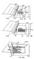
- the endmost label 128 is then cut from the roll 120 by a scissors 1020, a cutter 1022 incorporated into the printer housing 1010, or other conventional means, or is separated along the microperforations between the labels 128, and formed into a decal assembly 2000 as shown in Figure 4, using, for example, apparatus 10 as shown diagrammatically in Figure 2 or using a hand brayer 1030, as shown in Figure 3.
- the decal assembly 2000 comprises a backing web 112, the label 128, an adhesive web 106 applied over the label 128 and the backing web 112, and a releasable liner web 102 carrying the adhesive web 106, and positioned over the label 128; the label 128 and the adhesive web 106 over the label 128 defining the actual decal.
- Suitable adhesives for adhesive web 106 are 3M #9457, 3M #457MP, 3M #9172, and 3M #932FL, which are commercially available from 3M.
- the releasable web 102 is peeled back to reveal the adhesive web 106, the label 128, and the backing web 112.
- the decal i.e., label 128 and the adhesive web 106 covering label 128) can then be separated from the surrounding adhesive web 106 and the backing web 112 as shown in Figure 6 and applied to a surface.
- FAV sheeting can be used for the label 128, and where the decal is to be applied to a vehicle body, license plate sheeting or validation sheeting can be used for the label 128.
- clear overlaminate sheeting for example, 3M #7735FL clear overlaminate sheeting, available commercially from 3M
- This can be accomplished by adhering the overlaminate sheeting to the printed face of the label 128 prior to its assembly to the releasable web, the adhesive web, and the backing web, using the apparatus described below.
- the master 120' shown in Figure 7, comprises a thermal transfer printable strip laminated over a portion of its width and its full length with retroreflective sheeting 2002; retroreflective sheeting 2002 can be adhered to the master 120' by a web of suitable adhesive 2004 using conventional methods.
- the thermal transfer printable strip can be a polymer strip such as "Kimdura,” a polypropylene polyester, or any other material which is resistant to heat and water for use in a vehicle interior.
- micro-perforation can also be provided at the inner edge of the retroreflective sheeting 2002 to define a line of separation 2006 between the two halves of each label 128'.
- the master 120' is printed as described above with respect to master 120. It is envisioned that the retroreflective portion of the label 128' will be printed for use as a decal, while the unlaminated portion of the label 128' will be printed for use as a receipt accompanying the decal.
- the individual label 128' is folded along the line of separation, and then inserted into the apparatus 10 to make a decal assembly 2000' comprising a backing web 112, the folded label 128', an adhesive web 106 applied over the folded label 128' and the backing web 112, and a releasable liner web 102 carrying the adhesive web 106, and positioned over the folded label 128'.
- Folded label 128' is placed in the apparatus 10 with the laminated retroreflective portion facing the adhesive web 112 and the unlaminated portion facing the backing web 112.
- Label 12' can be folded either with the printing facing inwardly or outwardly, depending upon the desired application. Because of the fold, only the laminated portion is covered by adhesive web 106. Once label 128' with adhesive web 106 is separated from backing web 112. the laminated and unlaminated portions can be separated from each other along the micro-perforated line of separation, and the laminated portion covered by adhesive web 106 defines the actual decal.
- Figure 35 shows a license plate tax decal assembly 2000a similar in type to decal assembly 2000 shown in Figures 4-6.
- the fixed information 126 printed on the master 120 comprises, for example, the state (in this case, Minnesota) and a legend identifying the decal (in this case, "94-TAXES PAID-94"); other information, such as some type of logo (indicated in Figure 35 by reference letter L) can also be included.
- variable information 126a added to the master 120 at the Motor Vehicle Department Office comprises, for example, the license plate number (shown in Figure 35 as "ABC 123"); information identifying the vehicle, for example by make, style and color (shown in Figure 35 as "FORD-2DR-BLUE”); and the vehicle identification number ("A5678JKG9907543" in Figure 35).
- the master 120 preferably is retroreflective FAV sheeting, although other types of sheeting can also be used.
- Figure 36 shows a registration decal assembly 2000b also similar in type to decal assembly 2000 shown in Figures 4-6.
- the fixed information 126 printed on the master 120 comprises the state (again, Minnesota).
- the variable information 126a added to the master at the Motor Vehicle Department Office comprises, for example, the license plate characters (shown in Figure 36 as "MNOPQR") and a bar code representing the license plate characters (indicated in Figure 36 by reference letter B).
- MNOPQR license plate characters
- B bar code representing the license plate characters
- police officers equipped with a bar code reader can readily read the bar code; through conventional technology, information about the vehicle can then be obtained through a computer linked to the bar code reader.
- the master 120 preferably is retroreflective sheeting, although again, other types of sheeting can also be used.
- decal assembly can be used for other applications, such as numbers for houses, boats, snowmobiles, etc. and on vehicle license plates.
- the fixed information is omitted in a decal assembly 2000c providing a house, boat, or snowmobile number.
- the number (shown in Figure 37 as "123") is printed as the variable information 126A, and is then laminated prior to assembly using clear overlaminate sheeting 114, as described above with respect to a vehicle body decal.
- the number can be printed normally or in reverse (negative).
- variable information 126a comprises the license characters (shown in Figure 39 as "1234567") and the adhesive web 106 is applied to the printed side of the label 128.
- the release web is removed from the decal assembly, the label is removed from the backing web, and then the label is applied to an acrylic, polyester, or similar clear plastic plate which can be fastened to the vehicle.
- Figure 40 shows a two-part vehicle registration decal assembly 2000a' similar in type to decal assembly 2000' shown in Figures 8 and 9.
- the portion facing releasable web 102 comprises the decal portion to be adhered to a vehicle window, and can be printed as described above with respect to Figure 36.
- the portion facing the backing web 112 comprises the receipt portion.
- the fixed information 126 printed on the receipt portion of the master 120 comprises an identifying legend (in this case, "STATE OF MINNESOTA MOTOR VEHICLE REGISTRATION").
- variable information 126a added to the master at the Motor Vehicle Department Office comprises, for example, the license plate characters (shown in Figure 37 as "MNOPQR”); the vehicle identification number (shown in Figure 37 as "JK632585622178MNB”); information identifying the vehicle, for example by make and style (shown in Figure 37 as "2 DR CORVETTE”); the date of registration (shown in Figure 37 as "05/12/95”); and the name and address of the vehicle owner.
- FIG. 10 there is shown a first embodiment of apparatus for making a decal assembly.
- the apparatus is generally designated by the numeral 10.
- Apparatus 10 includes a lower frame member or base 12 and an upper frame member 14.
- the lower frame member 12 consists of spaced-apart side plates 20 and 22 secured in spaced-apart relationship by transversely extending spacer rod 24.
- the inner faces of the side plates 20 and 22 are provided with horizontally extending grooves 26a and 26b which provide mounting means to accommodate the insertion of feed rolls as will be explained hereafter.
- the side plates 20 and 22 are shown as each rectangular, having a bottom edge 30 which serves as a supporting surface or stand for the apparatus 10 and a horizontal top edge 32.
- the upper frame member 14 includes a pair of spaced-apart side plates 40 and 42.
- the side plates 40 and 42 are shown as each having top and bottom edges 44 and 46 and front and rear edges 50 and 52, respectively.
- An angular surface 54 extends between the bottom edge and the front edge to facilitate access to the nip rollers for loading and unloading.
- Plates 40 and 42 are pivotally mounted to lower plates 20 and 22 by means of pivot link 60.
- the bottom edge 46 of the upper side plates 40 and 42 rests on the horizontal top edge 32 of the lower side plates 20 and 22.
- the upper frame member 14 is rearwardly tilted about pivot link 60 to a position in which the rear surfaces of the lower end plates 20 and 22 engage the lower edges 46 of the upper end plates 40 and 42 to provide access for loading and unloading.
- Feed material is secured in the upper frame member 14 by inserting a feed roll 110 into slots 62a and 62b extending vertically in the inner surface of the opposite plates 40 and 42.
- An upper nip roller 64 extends transversely between the side plates 40 and 42 of the upper frame member 14 positioned adjacent the lower edge 42 of the plates 40 and 42.
- the upper nip roller 64 includes an axial shaft 66 which is rotatable in a suitable bearings or bushings 70.
- a stop nut or cap, not shown, is provided at the left end of the shaft 66, as viewed in Figure 10.
- the shaft 66 is covered by a cylindrical roller member 72 of resilient material such as rubber.
- the shaft 66 projects exteriorly of the side plate 42 and is shown carrying a hand crank 74 for manually rotating the roller 72 and shaft 66.
- the roller 66 can be powered by an electrical driven motor.
- a pinion gear 76 is secured to the shaft 66 adjacent the exterior surface of side plate 42, as best seen in Figure 13.
- a second, lower nip roller 80 extends transversely between the lower side plates 20 and 22 positioned parallel to the upper nip roller 64.
- the lower nip roller 80 can be vertically aligned with the upper nip roller 64 but preferably is forwardly displaced a small distance ahead of the upper nip roller 64 as for example 1/4" as seen in Figure 11.
- the lower nip roller 80 has a shaft 82 which is rotatable in bearings or journals 84 in the side plates 20 and 22.
- a lower pinion gear 86 is carried on the extension of shaft 82 at side plate 22.
- lower pinion gear 86 When the upper frame 14 is in its operative position, lower pinion gear 86 will engage the upper pinion gear 72 so that actuation of the upper nip roller shaft 66 by crank 72 or by other power means will impart rotation to both nip rollers 64 and 80.
- the device 10 can be used as a laminator or as an adhesive transfer device, for example to create decal assemblies.
- a lower feed roll 100 carrying a transferable adhesive is secured in the lower frame member 12.
- the lower feed roll 100 comprises a web 102 of flexible carrier material having release characteristics and an adhesive web or coating 106 on the upper surface of web 102. With the lower feed roll 100 in position, the end of the web 102 is extended over the lower roller 80 as shown in Figures 11 and 19.
- An upper feed roll 110 is positioned in engagement with the slots 62a and 62b in the interior surface of the upper side plates 40 and 42.
- the upper feed roll 110 in the case of adhesive transfer, will consist of a web 112 of material such as inexpensive paper or film having an affinity for adhesive.
- the end of the web 112 is extended between the nip rollers 64 and 80 with the end of the web adhesively secured to the web of a master 510 in the lower roll 100.
- the master 120 comprises a continuous sheet of material having an upper surface 122 and a lower surface 124.
- the upper surface 122 is imprinted with indicia 126 forming a repetitive pattern of labels 128 which have been pre-printed as desired; the master 120 can be any pre-printed documents or series of documents.
- labels 128 Prior to being fed into the machine, labels 128 can be pre-printed with both fixed and variable information, as previously discussed.
- a feed tray 130 which comprises a planar feeding surface 132 and opposite extending flanges 132a and 132b is suspended from the side plates 20 and 22 of the lower frame member 12. This is accomplished by engaging flanges 132a and 132b with the respective top edges 32 of the side plates 20 and 22.
- cutter bar 150 is shown which extends transversely between the lower side plates 20 and 22 rearwardly of the nip rollers 64 and 80.
- the cutter bar 150 has a sharpened edge 152 which allows the operator to easily manually sever a master 120 at any location as it is being processed when it emerges rearwardly from between the nip rollers 64 and 80.
- the master 120 is aligned on the feed tray 130 with the free edge of the master 120 positioned on the exposed adhesive web or coating 106 on the web 102 of lower feed roll 100.
- the slight forward protrusion of the lower nip roller 80 facilitates securing the master 120 to this location.
- This rotation will advance the web 112 of upper feed roll 110, web 102 of lower feed roll 100, and the master 120.
- the exposed adhesive coating or web 106 from the lower web 102 will be transferred to the lower surface 124 of the master 120.
- the upper web 112 will pick up any excess adhesive not transferred to the master 120, as for example areas outside the perimeter of the labels 128.
- the labels 128 should be narrower than the carrier web 102 and adhesive web 106, in order to ensure complete coverage of the individual labels 128 by the adhesive web 106. Further, the upper pick-up web 112 should be wider than the adhesive web 106 in order to ensure that picks up all of the excess adhesive web 106 surrounding the labels 128. The resulting decal assemblies 2000 can then be separated by severing between adjacent labels 128.
- the labels 128 are shown as being on a continuous strip which has been pre-printed with the desired indicia 126 and 126a.
- a single label 128 can be printed with the required fixed indicia 126 and variable indicia 126a and then separated from the master 120 and advanced through the machine 10 in the same manner as the master 120, as described in the immediately preceding paragraph.
- the master 120 (or a single label 128) can be oriented either with the indicia 126 and 126a facing upwardly or downwardly, depending on the user's requirements. For example, if the adhesive-coated labels 128 are to be applied to the inside of a window, the label 128 would be in most cases fed into the machine 10 with the printing 126 and 126a downwardly positioned so adhesive 106 would be applied over the printing 126 and 126a.
- the apparatus 10 also can apply lamination to either the top or bottom surfaces of a substrate or adhesive to the top or bottom surfaces of a substrate or to both, by substituting a web of laminating material for the lower carrier web 102 or the upper pickup web 112.
- the device 10 can also perform combination operations of applying both a laminate and an adhesive to a substrate.
- the characteristics of the lower carrier web 102 are such that the adhesive 106 is non-aggressive adhesive loosely adhered to the surface of the web 112 (although, as will be appreciated by those of skill in the art, adhesive 106 must aggressively adhere to upper pickup web 112 and label 128.
- the lower carrier web 102 serves as a peelable covering which can be stripped away at the time the label 128 is to be used by adhesively applying the label 128 to a surface.
- One significant advantage of the device 10 is that the lower and upper feed rolls 100 and 110 can be provided to the end user pre-wound and properly tensioned so as not to overrun during operation.
- the proper tensioning of the feed rolls 100 and 110 is accomplished by means of a tensioning device, best seen in Figures 16 and 17, which is equally usable with both rolls 100 and 110.
- a tensioning device best seen in Figures 16 and 17, which is equally usable with both rolls 100 and 110.
- a tensioning device best seen in Figures 16 and 17, which is equally usable with both rolls 100 and 110.
- a feed roll core 200 is shown about which is wound the roll of web material of either roll 100 or 110.
- the core 200 is a cylinder of cardboard or plastic having an end face 210 and an interior wall 212 which receives an end cap 214.
- the end cap 214 can be of molded plastic or other similar material, and has a cylindrical interior wall 216.
- An axially-extending boss 220 is formed in the end cap 214 concentric with cylindrical interior wall 216.
- An axial bore 222 extends through boss 220.
- the end cap 214 is positioned slightly inwardly of the end face 210 of the feed roll core 200 and can be adhesively secured in place to the interior wall 212 of the feed roll core 200.
- a circular end plate 230 abuts the end face 210 of the core 200 and has a diameter slightly greater than the diameter of the core 200.
- the end plate 230 has a central aperture 240 which receives the threaded shaft of bolt 246.
- a nut 250 engages the threaded end of the bolt 246 exterior of the inner end of the cap 214.
- a spring 252 is interposed between the nut 250 and the inner end of the cap 214.
- the head of the bolt 246 bears against the exposed outer surface of the end plate 230 and the position of the nut 250 determines the frictional resistance that exists between the interior surface of the end plate 230 and the end face 210 of the core 200 of the roller. This tension is pre-adjusted by the manufacturer to provide the proper roll tension depending upon the type of material size of the material, thickness of the material and other factors.
- Mounting tabs 260a and 260b project outwardly from the end plate 230 and are engageable in the mounting slots 26a and 26b and 62a and 62b provided respectively on the interior surfaces of the lower side plates 20 and 22 and the upper side plates 40 and 42 of the applicator device.
- the feed rolls can be supplied with various types of feed stock webs such as clear laminates, paper for removing excess adhesive or rolls of material having a loose adhesive coating and a release coating on the opposite surface.
- Figures 23 and 24 show a second alternate embodiment of the apparatus which is generally designated by the numeral 400. Elements which are the same or similar to elements described with respect to the preceding figures are identified by the same numerals.
- the apparatus 400 of Figures 23 and 24 has a frame comprising opposite side walls 436 and 438.
- the side walls 436 and 438 are again provided with vertically extending grooves 62a and 62b and horizontally extending grooves 26a and 26b which accommodate the insertion of feed rolls 110 and 100, respectively.
- the side walls 436 and 438 of the frame are fixed and separation of nip rollers 64 and 80 is accomplished by means of a gib plate arrangement as will be explained hereafter.
- the feed rolls 100 and 110 are positioned as close to the nip rollers 64 and 80 as possible to maintain accurate feeding and to minimize misalignment. It may be desirable to provide positive biasing means to urge feed roll 100 rightwardly as shown in Figure 23.
- a link 430 is pivotally secured at pivot point 432 to the interior of the side wall 436.
- a similar link can be disposed on the interior side wall 438.
- a spring 434 is disposed below the slot 26a.
- the nip rollers 64 and 80 be separated to provide access for purposes of loading the apparatus.
- access was provided by a two-portion frame arrangement in which one portion of the frame is pivotal with respect to the other.
- the lower nip roller 80 extends between the interior side walls of the side plates 436 and 438 and is mounted at opposite ends in bearings 440.
- the upper nip roller 64 is provided with opposite stub shafts 444a and 444b which are received respectively in bearings 446a and 446b in opposite gib plates 450 and 452.
- Gib plates 450 and 452 are vertically slidable and are upwardly biased by springs 460.
- rollers 64 and 80 are shown in a closed position in which they are in contact or close engagement.
- the nip rollers 64 and 80 are maintained in position by shaft 462 which is operated by nip engagement lever 470.
- Shaft 462 has notches or grooves 480 at either end adjacent the inner walls of side plates 436 and 438.
- shaft 462 will be rotated, bringing notches or grooves 480 into engagement with the upper ends of the gib plates 450 and 452. This will allow the gib plates 450 and 452 and nip roller 64 to move upwardly separating from lower nip roller 80.
- the shaft 462 is rotated into engagement with the gib plates 450 and 452 to force the gib plates 450 and 452 and upper nip roller 64 downwardly into engagement with the lower roller 80, overcoming the bias of the springs 460.
- the apparatus is generally designated by the numeral 600 and includes a housing generally designated by the numeral 612 having a base 614. opposite side walls 616 and 618. a top 620 and a rear wall 622.
- the rear wall 622 of the housing is upwardly and forwardly inclined at panel 622a from the base 614 to a location where the rear wall extends vertically at panel 622b.
- a discharge opening 630 is defined between the panels 622a and 622b through which the substrate and processed articles are discharged.
- an upper nip roller 64 extends transversely between the side walls 650 and 652 of the frame 642 spaced rearwardly from the edge of the side walls 650 and 652.
- the upper nip roller 64 includes an axial shaft 66 rotatable in suitable bearings or bushings 70 at opposite ends.
- the shaft 66 is covered by a cylindrical roller member 72 of resilient material such as rubber.
- Shaft 66 extends exteriorly of the side plate 618 and is shown carrying a hand crank 74 for manually rotating the roller and shaft.
- the rollers 64 and 80 can be powered by an electrical motor, not shown.
- a pinion gear 76 is secured to one end of the shaft 66 adjacent the interior surface of the side plate 618 .
- a second, lower nip roller 80 extends transversely between the side walls 616 and 618 positioned parallel to the upper nip roller 64.
- the lower nip roller 80 can be vertically aligned with the upper nip roller 64 but preferably is forwardly displaced a distance forward of the upper nip roller 64, as for example approximately 1/4" as best seen in Figure 30.
- the lower nip roller 80 has a shaft 82 which is rotatable in bearings 84 located at the interior of the opposite side walls.
- a pinion gear 86 is mounted at one end of the shaft 82.
- Pinion gear 86 engages the pinion gear 76 on the upper nip shaft 66 so that actuation of the upper nip roller 64 by means of the crank 74 or other power means will impart opposite rotation to both nip rollers 64 and 80 as indicated by the arrows in Figure 32.
- a primary advantage of the present invention is that various substrates can be provided to the user in a self-contained, ready-to-use cartridge 640 which allows the user simply to select and insert the appropriate cartridge.
- the device of the present invention can be used for multiple purposes for adhesive transfer and lamination. Adhesive can be transferred to either surface of the master and can be a dry adhesive.
- the cartridge 640 includes a lower feed roll 100 and an upper feed roll 110 as previously described, each containing a web of film or other flexible substrate material.
- the cartridge 640 includes a frame 642 having opposite side walls 650 and 652, a top 654, and bottom 656.
- a front wall 660 has a substantially rectangular opening 662 therein.
- the side walls 650 and 652 of cartridge 640 have horizontal recesses 662 provided therein for receiving a feed tray 670.
- Feed tray 670 has of a planar feeding surface 672 with opposite extending flanges 674 which flanges are removably insertable in the horizontal recesses 662 of cartridge 640.
- a wiper assembly 680 is mounted on the upper surface of the feed tray 670 as seen in Figures 25, 30, and 30A.
- the wiper assembly 680 has a bar 682 which extends transversely across the feed tray 670 adjacent the entrance to the nip area.
- the bar 682 has a pad 684 of resilient or soft material such as felt, soft plastics, fabric or rubber, which lightly engages the master as it passes between the wiper assembly 680 and the tray feeding surface 672.
- the wiper assembly 680 serves several functions, in that it cleans, smooths and guides the master as it enters the nip between the nip rollers 64 and 80.
- a particularly important function of the wiper assembly 680 is to tension the master substrate keeping it flat and aligned with the laminate and adhesive webs resulting in better alignment especially when feeding sheets intermittently.
- the wiper assembly 680 also has an arm 690 which is upwardly biased by a spring 692.
- Arm 690 is pivotally attached to the edge of the feed tray 670 at fulcrum 694 so that the wiper assembly 680 is pressed into light engagement with the material passing beneath the pad 684.
- the wiper bar 682 can be lifted to facilitate loading a master by manually depressing the outer end of the arm 690 against the force of spring 692.
- the pad 684 is replaceable as required.
- a blade 702 having a cutting edge extends transversely adjacent the discharge opening 630.
- the blade 702 is movable vertically upward from a non-actuated position to a cutting position by means of lever 704 to which the blade 702 is attached.
- Lever 704 is pivotally secured to the interior of the housing side wall 616 at pivot rod 706. Downward movement of the lever 704 at handle 710 will move the blade 702 upward into engagement with anvil bar 712 which is fixed at the bottom of panel 622b and extends transversely.
- the blade 702 is mounted on a carrier 714 by means of pins 720 having compression springs 722 thereon which bias the blade 702 toward the anvil bar 712.
- the flat surface of the blade 702 moves along the anvil bar 712 which provides a self-cleaning action.
- the upper end of panel 622a is slightly convexly curved at 720 as seen in Figure 30 to facilitate smooth discharge of the item being processed.
- the area indicated by the numeral 720 can be coated with a suitable low-frictional material such as that sold under the trademark "Teflon".
- a significant advantage of the present invention is that the lower and upper feed rolls 100 and 110 are provided to the user pre-wound and properly tensioned as previously described, so as not to overrun during operation and to provide proper tracking.
- the proper tensioning of the feed rolls 100 and 110 is accomplished by means of the tensioning device previously described with respect to Figures 15 and 16.
- Horizontal upper mounting slots 724a and 724b and horizontal lower mounting slots 726a and 726b are provided on the interior surfaces of the cartridge side walls 650 and 652 for receiving mounting tabs 260a and 260b projecting outwardly from the end plates 230 of the tensioning devices provided in feed rolls 100 and 110.
- the user simply selects the appropriate cartridge 640 and positions the cartridge 640 in the opening at the front side of the housing 612.
- the cartridge 640 is locked in place in the housing 612 in a vertical position by locking detent members.
- the feed rolls 100 and 110 can be various types of stock such as clear laminates, paper or film for removing excessive adhesive or rolls of material having a loose adhesive coating and a release coating on the opposite surface.
- the feed tray 670 is inserted in a generally horizontal position in the opposite horizontal recesses 664 in the cartridge side walls 650 and 652.
- the device 400 can be used as a lamination device or as an adhesive transfer device.
- the lower feed roll 100 comprises a film carrying an easily transferable adhesive.
- the upper feed roll 110 would typically be a web of flexible carrier material having release characteristics on a lower surface and adhesive coating on the other surface. With rolls of this type in position, the end of the web of the lower feed roll 100 is extended over the lower nip roller 80.
- the upper feed roll 110 in the case of adhesive transfer, will consist of a web of material such as inexpensive paper or film, having an affinity for adhesive. The end of the web is extended between the nip rollers 64 and 80 with the end of the web adhesively secured to the web of the master in the lower feed roll 100.
- the master 120 is as previously described with respect to Figures 20 to 22.
- the master 120 is aligned on the feed tray 670 with the leading free edge of the master 120 positioned on the exposed adhesive surface 106 of the lower feed stock material 102 at the nip roller interface.
- the slight forward protrusion of the lower nip roller 80 facilitates securing the master 120 at this location.
- the web 112 of the upper feed roller 110 is fed from the cartridge 640 to the nip roller interface on the upper side of master 120.
- the rotation will also advance the upper web 112, the lower web 102, and the master 120.
- the master 120 is smoothed, guided, and wiped clean as it passes between the wiper 680 and the upper surface of the tray.
- the exposed adhesive 106 from the lower web 102 will be transferred to the lower surface of the master 120.
- the upper web 112 will pick up any excessive adhesive not transferred to the master 120, as for example adhesive 106 in the areas outside the perimeter of the label areas 128. As previously described, the decal assembly can then be easily severed from the webs as it emerges from the discharge opening at the rear of the machine.
- the master 120 can be oriented with either printing or indicia facing upwardly or downwardly depending on the user's requirements.
Landscapes
- Mechanical Engineering (AREA)
- Engineering & Computer Science (AREA)
- Labeling Devices (AREA)
- Making Paper Articles (AREA)
- Folding Of Thin Sheet-Like Materials, Special Discharging Devices, And Others (AREA)
- Laminated Bodies (AREA)
- Adhesive Tapes (AREA)
- Decoration By Transfer Pictures (AREA)
- Lining Or Joining Of Plastics Or The Like (AREA)
- Sheets, Magazines, And Separation Thereof (AREA)
- Application Of Or Painting With Fluid Materials (AREA)
- Diaphragms For Electromechanical Transducers (AREA)
- Manufacture Of Switches (AREA)
- Replacement Of Web Rolls (AREA)
- Rolls And Other Rotary Bodies (AREA)
- Unwinding Webs (AREA)
- Adornments (AREA)
- Golf Clubs (AREA)
- Battery Mounting, Suspending (AREA)
- Auxiliary Devices For And Details Of Packaging Control (AREA)
- Impression-Transfer Materials And Handling Thereof (AREA)
- Coating Apparatus (AREA)
Abstract
Description
- The present invention relates to decals and stickers, that is, adhesive coated labels. More specifically, the invention relates to such labels which are retroreflective, and which are provided with variable printed material, and to a method of making same which can be implemented simply and inexpensively to produce individualized labels. The present invention also relates to apparatus for laminating items and which apparatus will also transfer adhesives to substrates for purposes of producing articles such as decals and stickers.
- All the states in the United States validate various motor vehicle-related requirements by issuing the vehicle owner a decal to place on the vehicle indicating compliance with the particular requirement These requirements include, but are not limited to, tax payment, vehicle mechanical inspection, emission inspections, payment for access to parking, and membership in the fire department.
- At present, the decals indicating compliance with all of these requirements are made in a central location and typically are issued by one of three means: (1) The decal is applied for and returned to the recipient by mail from a central location. (2) The decal is issued from several governmental offices in the state. (3) The decal is issued by large numbers of privately owned businesses in the state. Information placed on these decals has at most a control number for the state to track the decals. In many states, the control number is essentially useless, because of the difficulty of keeping track of the recipient, where the recipient places the decal with a particular control number, and who can enforce non-compliance. Frequently, the state only has partial control over the decals sent to a particular issuing location, and must trust the issuer to return information matching recipients with decals. Due to the foregoing difficulties, states often find tracking validation decals to be problematic.
- Also, fraud can be committed by stealing a decal rather than acquiring it through the proper procedures, by buying and using a counterfeit decal, and by purchasing a decal for one vehicle and using it on another vehicle (referred to as "transferring" the decal). One way to prevent fraud is to print, at the time of issue, vehicle specific information on a decal made from a material that cannot be counterfeited. This is difficult to do under present decal production systems, since the decals are produced at a central location using expensive, automated equipment.
- Such expensive automated equipment cannot be cost-justified for non-centralized governmental offices (such as state motor vehicle department offices) and privately-owned locations. Thus, decals issued from many governmental offices or privately-owned locations need a low cost system that can produce the same decals as expensive, automated equipment found at a central location.
- An example of such a system is disclosed in GB 931183.
- Based on the foregoing, there exists a need for a simple multi-purpose apparatus which can both serve to apply laminates to documents and papers and which will also serve to apply adhesive, including dry adhesives, to materials of various sizes so a wide variety of labels and decals can be produced. The apparatus of the present invention can apply clear plastic laminates to master substrates of various sizes and can also transfer adhesive to substrates of various sizes not being limited by length. Adhesive transfer can be applied to either surface of the item as required. The apparatus can also apply dry adhesives from double sided release coated liners to a substrate.
- According to a first aspect of the present invention, there is provided a removable cartridge in accordance with
Claim 1. - According to a second aspect of the present invention, there is provided an apparatus in accordance with Claim 8.
- Preferred embodiments provide a multi-purpose laminating and adhesive transfer apparatus for producing an adhesive, retroreflective label in accordance with the present invention.
- In one embodiment, a multi-purpose laminating and adhesive transfer apparatus is provided which has a frame or housing with mounting means for receiving a cartridge which is insertable to supply material to perform the necessary laminating or adhesive transfer operation. The cartridge has a box-like housing in which upper and lower supply rolls containing webs of laminating or adhesive transfer material are rotatively secured. The rolls have tensioning caps which can be adjusted to prevent the supply rolls from overrunning as they pay-out material. The caps are pre-set in accordance with the operation being performed and the characteristics of the material. The tensioning caps can be pre-set by the material supplier at the time they are inserted into the cartridge. The user selects the cartridge appropriate to the operation to be performed.
- First and second nip rollers extend transversely in the housing at a location intermediate the cartridge supply rollers. The nip rollers have a resilient coating and engage one another or are slightly spaced-apart in parallel relationship to one another. Preferably the lower nip roller is displayed forwardly from the upper nip roller in the direction of the cartridge. An actuator, which can be powered or can be manual such as a hand crank, is provided for driving or rotating at least one of the nip rollers which, in turn, drives the other roller.
- A feed tray is removably mountable to the housing to facilitate feeding the article to be processed. Preferably the feed tray is removably secured in a general horizontal location aligned with the nip. The feed tray carries a transversely extending guide and wiper which smooths, cleans and positions the master fed along the tray. A discharge opening is provided at the rear of the housing and a cutter blade extends transversely across the housing adjacent the discharge. The cutter blade can be manually actuated by a lever to upwardly sever the substrate at a desired location is conjunction with an anvil bar.
- By way of example, the lower feed roll can comprise a flexible film with an adhesive coating. The upper feed roll comprises a supply of film which has an affinity for adhesive. The upper and lower films are fed between the nip rollers. The tray is placed in position and a pre-printed master such as a master containing labels repetitively printed on a sheet can be fed via the tray to the interface between the nip rollers passing between the tray surface and the wiper. Adhesive will be transferred from the bottom film to the labels with excessive adhesive being picked up by the top film. The labels are now provided with an adhesive being picked up by the top film. The labels are now provided with an adhesive and are attached to the lower film and can be severed from one another by the cutting blade at the discharge opening. The labels can be peeled from the film substrate when used.
- The invention is better understood by reading the following Detailed Description of the Preferred Embodiments with reference to the accompanying drawing figures, in which like reference numerals refer to like elements throughout, and in which:
- Figure 1 is a diagrammatic view illustrating the steps of a method for printing variable information on a label;
- Figure 2 is a simplified side diagrammatic view of apparatus for making a decal assembly using the label of Figure 1:
- Figure 3 is a perspective view of a hand brayer being used to make a decal;
- Figure 4 is a cross-sectional view of a decal assembly;
- Figure 5 is a perspective view of the decal assembly of Figure 4 showing the release liner being peeled away;
- Figure 6 is a perspective view of the decal assembly of Figure 5 showing the release liner removed and the decal being peeled away from the backing;
- Figure 7 is a top plan view of a master laminated along a portion of its width with a second material, for use in an alternate embodiment of the decal assembly;
- Figure 8 is a perspective of an alternate embodiment of a decal assembly using the master of Figure 7. folded in half along its length, showing the release liner and the label being separated from the backing sheet;
- Figure 9 is a cross-sectional view of the decal assembly of Figure 8;
- Figure 10 is a perspective view of a transfer device shown in an operative position:
- Figure 11 is a sectional view of the transfer device shown in an operative position taken along line 11-11 of Figure 10;
- Figure 12 is a partial side view showing the device in an open or loading position;
- Figure 13 is a view taken along lines 13-13 of Figure 10 with the feed rolls removed;
- Figure 14 is an exploded perspective view of the device;
- Figure 15 is an end view of a feed roller;
- Figure 16 is a sectional view taken along line 16-16 of Figure 14;
- Figure 17 is an exploded view showing the tensioning cap positioned at the end of a feed roll;
- Figure 18 is a partial rear perspective view showing the cut-off blade;
- Figure 19 is a view showing a master fed between the nip rollers;
- Figure 20 is a plan view of the feed master showing adhesive applied;
- Figure 21 is a plan view of the upper feed web showing pick up of excess adhesive thereon:
- Figure 22 shows the removal of adhesive from the lower web;
- Figure 23 is a perspective view of an alternate embodiment of the transfer device;
- Figure 24 is a sectional view taken along line 24-24 of Figure 23;
- Figure 25 is a perspective view of the transfer apparatus of the present invention;
- Figure 26 is a perspective view of the supply roll containing a cartridge removed from the apparatus;
- Figure 27 is a sectional view taken along line 27-27 of Figure 26;
- Figure 28 is a perspective view illustrating the installation of a cartridge;
- Figure 29 is a detail view of the cutter mechanism;
- Figure 30 is a side view, partly in section, showing the cartridge in place and a master bring fed into the device;
- Figure 30A is a detail view of the wiper as indicated in Figure 30;
- Figure 31 is a sectional view taken along line 31-31 of Figure 30;
- Figure 32 is a detail view of the nip rollers;
- Figure 33 is a sectional view taken along line 33-33 of Figure 32;
- Figure 34 is a side view showing a master being fed between the nip rollers;
- Figure 35 shows a license plate tax decal assembly;
- Figure 36 shows a registration decal assembly;
- Figure 37 shows a label for use in a decal assembly providing a house, boat, or snowmobile number;
- Figure 38 shows a decal assembly incorporating the label of Figure 37;
- Figure 39 shows a decal assembly for a vehicle license plate; and
- Figure 40 shows a two-part vehicle registration decal assembly.
- It should be noted that the preferred embodiment of the present invention is illustrated in Figures 25 to 34 only.
- The remaining figures and associated description are only included to assist in the understanding of the present invention.
- In describing the preferred embodiment of the present invention illustrated in the drawings, specific terminology is employed for the sake of clarity. However, the invention is not intended to be limited to the specific terminology so selected, and it is to be understood that each specific element includes all technical equivalents which operate in a similar manner to accomplish a similar purpose.
- Referring now to Figures 1-3, there is shown
simplified apparatus 1000 for making aretroreflective decal assembly 2000 of the type shown in Figures 4-6 or a decal assembly 2000' of the type shown in Figures 8 and 9. Amaster 120 for use in the method of assembly is chosen based upon the particular application of the decal. For a window decal,master 120 preferably is an adhesive-receptive sheeting such as die cut face adhering verification ("FAV") sheeting wound on a reel or spool as shown in Figure 1. A suitable FAV sheeting, which is difficult to counterfeit, is 3M #2500 FAV sheeting, which is commercially available from 3M. For a decal to be adhered to a vehicle body,master 120 can be, for example, 3M #3750 license plate sheeting or 3M #5330 validation sheeting, both of which are commercially available from 3M. - During manufacture, die cutting (using, for example, a conventional rotary die system) can be used to microperforate the corners for rounding and to microperforate the edges between
adjacent decals 128 to facilitate the separation ofindividual decals 128 from each other. The "weed" (i.e., the scrap around the finished edges of the decals) can be stripped following die cutting to provide RCR (i.e., rounded) corners. -
Fixed information 126 can be pre-printed in conjunction with the manufacture of thedecals 128, for example in multiple colors using Flexographic™ processing, an inexpensive, high-speed printing process which uses flexible plates on a cylinder for printing graphic information in colored ink, and which is well-known to those of skill in the art. Variable information 126a can be printed easily and inexpensively on an on-demand basis using an on-site computer-controlledthermal transfer printer 1002. - A diagrammatic representation of a
thermal transfer printer 1002 and acomputer controller 1004 therefor, for printing variable information 126a on themaster 120 is shown in Figure 1.Thermal transfer printer 1002 is of conventional design; for example, a 'Zebra Stripe" printer (which is commercially available from Zebra Technologies Corporation of Vernon Hills, Illinois) can be used. Themaster 120 with pre-printed fixedinformation 126, and wound on a reel or spool, is placed in theprinter housing 1010.Computer controller 1004 is programmed to allow the operator to input the variable information into variable information fields and print out the variable information onto a thermal wax ribbon 1012 using theprinter print head 1014. For example, for a vehicle-related decal assembly, the display screen of thecomputer controller 1004 can prompt the operator at the issuing state motor vehicle department to obtain from the vehicle owner and input into thecomputer controller 1004 the necessary variable vehicle and owner information. Thecomputer controller 1004 can be linked to a central computer, so that the vehicle and owner information can be centrally accessed by state authenties. -
Printer 1002 aligns thelabels 128 using timing marks pre-printed onmaster 120 along with the fixedinformation 126. The variable information 126a is then transferred from thethermal wax ribbon 1014 onto an individual decal. A suitable thermal transfer ribbon is 3M #VP5130 black thermal transfer ribbon, which is commercially available from 3M. Theendmost label 128 is then cut from theroll 120 by ascissors 1020, acutter 1022 incorporated into theprinter housing 1010, or other conventional means, or is separated along the microperforations between thelabels 128, and formed into adecal assembly 2000 as shown in Figure 4, using, for example,apparatus 10 as shown diagrammatically in Figure 2 or using a hand brayer 1030, as shown in Figure 3. - The
decal assembly 2000 comprises abacking web 112, thelabel 128, anadhesive web 106 applied over thelabel 128 and thebacking web 112, and areleasable liner web 102 carrying theadhesive web 106, and positioned over thelabel 128; thelabel 128 and theadhesive web 106 over thelabel 128 defining the actual decal. Suitable adhesives foradhesive web 106 are 3M #9457, 3M #457MP, 3M #9172, and 3M #932FL, which are commercially available from 3M. As shown in Figure 5, thereleasable web 102 is peeled back to reveal theadhesive web 106, thelabel 128, and thebacking web 112. The decal (i.e.,label 128 and theadhesive web 106 covering label 128) can then be separated from the surroundingadhesive web 106 and thebacking web 112 as shown in Figure 6 and applied to a surface. - As indicated above, where the decal is to be applied to a window, FAV sheeting can be used for the
label 128, and where the decal is to be applied to a vehicle body, license plate sheeting or validation sheeting can be used for thelabel 128. Because of the exposure which body decals receive, it is desirable to provide clear overlaminate sheeting (for example, 3M #7735FL clear overlaminate sheeting, available commercially from 3M) to the printed, non-adhesive face of the decal. This can be accomplished by adhering the overlaminate sheeting to the printed face of thelabel 128 prior to its assembly to the releasable web, the adhesive web, and the backing web, using the apparatus described below. - An alternate embodiment of the decal assembly 2000' is shown in Figures 8 and 9. For making decal assembly 2000', the master 120', shown in Figure 7, comprises a thermal transfer printable strip laminated over a portion of its width and its full length with
retroreflective sheeting 2002;retroreflective sheeting 2002 can be adhered to the master 120' by a web of suitable adhesive 2004 using conventional methods. For vehicle applications, the thermal transfer printable strip can be a polymer strip such as "Kimdura," a polypropylene polyester, or any other material which is resistant to heat and water for use in a vehicle interior. - In addition to providing micro-perforation at the corners and between individual labels 128', micro-perforation can also be provided at the inner edge of the
retroreflective sheeting 2002 to define a line ofseparation 2006 between the two halves of each label 128'. The master 120' is printed as described above with respect tomaster 120. It is envisioned that the retroreflective portion of the label 128' will be printed for use as a decal, while the unlaminated portion of the label 128' will be printed for use as a receipt accompanying the decal. Following its separation from the master roll, the individual label 128' is folded along the line of separation, and then inserted into theapparatus 10 to make a decal assembly 2000' comprising abacking web 112, the folded label 128', anadhesive web 106 applied over the folded label 128' and thebacking web 112, and areleasable liner web 102 carrying theadhesive web 106, and positioned over the folded label 128'. Folded label 128' is placed in theapparatus 10 with the laminated retroreflective portion facing theadhesive web 112 and the unlaminated portion facing thebacking web 112. Label 12' can be folded either with the printing facing inwardly or outwardly, depending upon the desired application. Because of the fold, only the laminated portion is covered byadhesive web 106. Once label 128' withadhesive web 106 is separated from backingweb 112. the laminated and unlaminated portions can be separated from each other along the micro-perforated line of separation, and the laminated portion covered byadhesive web 106 defines the actual decal. - Examples of different types of decals and decal assemblies are shown in Figures 35-40. Figure 35 shows a license plate tax decal assembly 2000a similar in type to
decal assembly 2000 shown in Figures 4-6. For decal assembly 2000a, the fixedinformation 126 printed on themaster 120 comprises, for example, the state (in this case, Minnesota) and a legend identifying the decal (in this case, "94-TAXES PAID-94"); other information, such as some type of logo (indicated in Figure 35 by reference letter L) can also be included. The variable information 126a added to themaster 120 at the Motor Vehicle Department Office comprises, for example, the license plate number (shown in Figure 35 as "ABC 123"); information identifying the vehicle, for example by make, style and color (shown in Figure 35 as "FORD-2DR-BLUE"); and the vehicle identification number ("A5678JKG9907543" in Figure 35). In this case, themaster 120 preferably is retroreflective FAV sheeting, although other types of sheeting can also be used. - Figure 36 shows a
registration decal assembly 2000b also similar in type todecal assembly 2000 shown in Figures 4-6. Fordecal assembly 2000b, the fixedinformation 126 printed on themaster 120 comprises the state (again, Minnesota). The variable information 126a added to the master at the Motor Vehicle Department Office comprises, for example, the license plate characters (shown in Figure 36 as "MNOPQR") and a bar code representing the license plate characters (indicated in Figure 36 by reference letter B). Police officers equipped with a bar code reader can readily read the bar code; through conventional technology, information about the vehicle can then be obtained through a computer linked to the bar code reader. In this case also, themaster 120 preferably is retroreflective sheeting, although again, other types of sheeting can also be used. - This type of decal assembly can be used for other applications, such as numbers for houses, boats, snowmobiles, etc. and on vehicle license plates. As shown in Figures 37 and 38, in a
decal assembly 2000c providing a house, boat, or snowmobile number, the fixed information is omitted. The number (shown in Figure 37 as "123") is printed as the variable information 126A, and is then laminated prior to assembly usingclear overlaminate sheeting 114, as described above with respect to a vehicle body decal. The number can be printed normally or in reverse (negative). - As shown in Figure 39, in a
decal assembly 2000d for a vehicle license plate, for example of the type used in the United Kingdom, the variable information 126a comprises the license characters (shown in Figure 39 as "1234567") and theadhesive web 106 is applied to the printed side of thelabel 128. For assembly into a license plate, the release web is removed from the decal assembly, the label is removed from the backing web, and then the label is applied to an acrylic, polyester, or similar clear plastic plate which can be fastened to the vehicle. - Figure 40 shows a two-part vehicle registration decal assembly 2000a' similar in type to decal assembly 2000' shown in Figures 8 and 9. For decal assembly 2000a', the portion facing
releasable web 102 comprises the decal portion to be adhered to a vehicle window, and can be printed as described above with respect to Figure 36. The portion facing thebacking web 112 comprises the receipt portion. For decal assembly 2000a', the fixedinformation 126 printed on the receipt portion of themaster 120 comprises an identifying legend (in this case, "STATE OF MINNESOTA MOTOR VEHICLE REGISTRATION"). The variable information 126a added to the master at the Motor Vehicle Department Office comprises, for example, the license plate characters (shown in Figure 37 as "MNOPQR"); the vehicle identification number (shown in Figure 37 as "JK632585622178MNB"); information identifying the vehicle, for example by make and style (shown in Figure 37 as "2 DR CORVETTE"); the date of registration (shown in Figure 37 as "05/12/95"); and the name and address of the vehicle owner. - Referring now to Figures 10 to 15, there is shown a first embodiment of apparatus for making a decal assembly. The apparatus is generally designated by the numeral 10. The terms "forward" and "rearward" or "front" and "rear" as used herein, refer to the orientation of the feed path through the device.
-
Apparatus 10 includes a lower frame member orbase 12 and anupper frame member 14. Thelower frame member 12 consists of spaced-apartside plates spacer rod 24. The inner faces of theside plates grooves 26a and 26b which provide mounting means to accommodate the insertion of feed rolls as will be explained hereafter. Theside plates bottom edge 30 which serves as a supporting surface or stand for theapparatus 10 and a horizontaltop edge 32. - The
upper frame member 14 includes a pair of spaced-apartside plates side plates bottom edges rear edges angular surface 54 extends between the bottom edge and the front edge to facilitate access to the nip rollers for loading and unloading. -
Plates lower plates pivot link 60. In the normal operative position, thebottom edge 46 of theupper side plates top edge 32 of thelower side plates upper frame member 14 is rearwardly tilted aboutpivot link 60 to a position in which the rear surfaces of thelower end plates lower edges 46 of theupper end plates - Feed material is secured in the
upper frame member 14 by inserting afeed roll 110 intoslots opposite plates - An upper nip
roller 64 extends transversely between theside plates upper frame member 14 positioned adjacent thelower edge 42 of theplates upper nip roller 64 includes anaxial shaft 66 which is rotatable in a suitable bearings orbushings 70. A stop nut or cap, not shown, is provided at the left end of theshaft 66, as viewed in Figure 10. - The
shaft 66 is covered by acylindrical roller member 72 of resilient material such as rubber. Theshaft 66 projects exteriorly of theside plate 42 and is shown carrying a hand crank 74 for manually rotating theroller 72 andshaft 66. Alternatively, theroller 66 can be powered by an electrical driven motor. Apinion gear 76 is secured to theshaft 66 adjacent the exterior surface ofside plate 42, as best seen in Figure 13. - A second, lower nip
roller 80 extends transversely between thelower side plates roller 64. Thelower nip roller 80 can be vertically aligned with the upper niproller 64 but preferably is forwardly displaced a small distance ahead of the upper niproller 64 as for example 1/4" as seen in Figure 11. Thelower nip roller 80 has ashaft 82 which is rotatable in bearings orjournals 84 in theside plates lower pinion gear 86 is carried on the extension ofshaft 82 atside plate 22. When theupper frame 14 is in its operative position,lower pinion gear 86 will engage theupper pinion gear 72 so that actuation of the uppernip roller shaft 66 by crank 72 or by other power means will impart rotation to both niprollers - As mentioned above, the
device 10 can be used as a laminator or as an adhesive transfer device, for example to create decal assemblies. In the case of use as an adhesive transfer device, alower feed roll 100 carrying a transferable adhesive is secured in thelower frame member 12. Referring to Figures 13 to 16, thelower feed roll 100 comprises aweb 102 of flexible carrier material having release characteristics and an adhesive web or coating 106 on the upper surface ofweb 102. With thelower feed roll 100 in position, the end of theweb 102 is extended over thelower roller 80 as shown in Figures 11 and 19. Anupper feed roll 110 is positioned in engagement with theslots upper side plates upper feed roll 110, in the case of adhesive transfer, will consist of aweb 112 of material such as inexpensive paper or film having an affinity for adhesive. The end of theweb 112 is extended between the niprollers lower roll 100. - Referring to Figures 19 to 22. the
master 120 comprises a continuous sheet of material having anupper surface 122 and a lower surface 124. Theupper surface 122 is imprinted withindicia 126 forming a repetitive pattern oflabels 128 which have been pre-printed as desired; themaster 120 can be any pre-printed documents or series of documents. Prior to being fed into the machine, labels 128 can be pre-printed with both fixed and variable information, as previously discussed. - Once lower and upper feed rolls 100 and 110 have been positioned, the
upper frame member 14 is rotated to a closed position bringing the niprollers webs master 120 compressed therebetween. Afeed tray 130 which comprises a planar feeding surface 132 and opposite extendingflanges 132a and 132b is suspended from theside plates lower frame member 12. This is accomplished by engagingflanges 132a and 132b with the respectivetop edges 32 of theside plates - Referring to Figure 21.
cutter bar 150 is shown which extends transversely between thelower side plates rollers cutter bar 150 has a sharpenededge 152 which allows the operator to easily manually sever amaster 120 at any location as it is being processed when it emerges rearwardly from between the niprollers - The
master 120 is aligned on thefeed tray 130 with the free edge of themaster 120 positioned on the exposed adhesive web or coating 106 on theweb 102 oflower feed roll 100. The slight forward protrusion of the lower niproller 80 facilitates securing themaster 120 to this location. - The operator then actuates the
device 10 by operating thecrank 74 which will rotate the upper niproller 60 and by means of the inter-engaging pinion gears, cause rotation of the lower niproller 80. This rotation will advance theweb 112 ofupper feed roll 110,web 102 oflower feed roll 100, and themaster 120. As themaster 120 proceeds between the niprollers web 106 from thelower web 102 will be transferred to the lower surface 124 of themaster 120. Theupper web 112 will pick up any excess adhesive not transferred to themaster 120, as for example areas outside the perimeter of thelabels 128. Thelabels 128 should be narrower than thecarrier web 102 andadhesive web 106, in order to ensure complete coverage of theindividual labels 128 by theadhesive web 106. Further, the upper pick-upweb 112 should be wider than theadhesive web 106 in order to ensure that picks up all of the excessadhesive web 106 surrounding thelabels 128. The resultingdecal assemblies 2000 can then be separated by severing betweenadjacent labels 128. - The
labels 128 are shown as being on a continuous strip which has been pre-printed with the desiredindicia 126 and 126a. Alternatively, asingle label 128 can be printed with the required fixedindicia 126 and variable indicia 126a and then separated from themaster 120 and advanced through themachine 10 in the same manner as themaster 120, as described in the immediately preceding paragraph. - Note that the master 120 (or a single label 128) can be oriented either with the
indicia 126 and 126a facing upwardly or downwardly, depending on the user's requirements. For example, if the adhesive-coatedlabels 128 are to be applied to the inside of a window, thelabel 128 would be in most cases fed into themachine 10 with theprinting 126 and 126a downwardly positioned so adhesive 106 would be applied over theprinting 126 and 126a. - The
apparatus 10 also can apply lamination to either the top or bottom surfaces of a substrate or adhesive to the top or bottom surfaces of a substrate or to both, by substituting a web of laminating material for thelower carrier web 102 or theupper pickup web 112. Thedevice 10 can also perform combination operations of applying both a laminate and an adhesive to a substrate. - The characteristics of the
lower carrier web 102 are such that the adhesive 106 is non-aggressive adhesive loosely adhered to the surface of the web 112 (although, as will be appreciated by those of skill in the art, adhesive 106 must aggressively adhere toupper pickup web 112 andlabel 128. Thus, thelower carrier web 102 serves as a peelable covering which can be stripped away at the time thelabel 128 is to be used by adhesively applying thelabel 128 to a surface. - One significant advantage of the
device 10 is that the lower and upper feed rolls 100 and 110 can be provided to the end user pre-wound and properly tensioned so as not to overrun during operation. The proper tensioning of the feed rolls 100 and 110 is accomplished by means of a tensioning device, best seen in Figures 16 and 17, which is equally usable with bothrolls feed roll core 200 is shown about which is wound the roll of web material of eitherroll core 200 is a cylinder of cardboard or plastic having anend face 210 and aninterior wall 212 which receives anend cap 214. Theend cap 214 can be of molded plastic or other similar material, and has a cylindricalinterior wall 216. An axially-extendingboss 220 is formed in theend cap 214 concentric with cylindricalinterior wall 216. Anaxial bore 222 extends throughboss 220. Theend cap 214 is positioned slightly inwardly of theend face 210 of thefeed roll core 200 and can be adhesively secured in place to theinterior wall 212 of thefeed roll core 200. - A
circular end plate 230 abuts theend face 210 of thecore 200 and has a diameter slightly greater than the diameter of thecore 200. Theend plate 230 has acentral aperture 240 which receives the threaded shaft ofbolt 246. Anut 250 engages the threaded end of thebolt 246 exterior of the inner end of thecap 214. Aspring 252 is interposed between thenut 250 and the inner end of thecap 214. The head of thebolt 246 bears against the exposed outer surface of theend plate 230 and the position of thenut 250 determines the frictional resistance that exists between the interior surface of theend plate 230 and theend face 210 of thecore 200 of the roller. This tension is pre-adjusted by the manufacturer to provide the proper roll tension depending upon the type of material size of the material, thickness of the material and other factors. - Mounting
tabs 260a and 260b project outwardly from theend plate 230 and are engageable in the mountingslots lower side plates upper side plates - Thus, inserting a supply of feed stock either in the upper or lower frames is easily accomplished. The existing or spent feed rolls are removed by sliding them outwardly to disengage the tabs from the slots. The new roll is inserted by aligning the mounting tabs with the slots and sliding the new feed roll into place.
- The feed rolls can be supplied with various types of feed stock webs such as clear laminates, paper for removing excess adhesive or rolls of material having a loose adhesive coating and a release coating on the opposite surface.
- Figures 23 and 24 show a second alternate embodiment of the apparatus which is generally designated by the numeral 400. Elements which are the same or similar to elements described with respect to the preceding figures are identified by the same numerals. The
apparatus 400 of Figures 23 and 24 has a frame comprisingopposite side walls side walls grooves grooves 26a and 26b which accommodate the insertion of feed rolls 110 and 100, respectively. In this embodiment, theside walls rollers - Because mounting
slots feed roll 110 will maintain it in the proper position. Preferably, the feed rolls 100 and 110 are positioned as close to the niprollers feed roll 100 rightwardly as shown in Figure 23. To this end, a link 430 is pivotally secured at pivot point 432 to the interior of theside wall 436. A similar link can be disposed on theinterior side wall 438. A spring 434 is disposed below the slot 26a. When thefeed roll 100 is inserted, link 432 can be rotated downwardly as indicated by the arrow and engaged with spring 434 to apply a biasing force to thefeed roll 100 to maintain it in a secure position. - As indicated above, it is desirable that the nip
rollers roller 80 extends between the interior side walls of theside plates bearings 440. Theupper nip roller 64 is provided withopposite stub shafts 444a and 444b which are received respectively inbearings 446a and 446b inopposite gib plates Gib plates springs 460. In Figure 24, therollers rollers shaft 462 which is operated by nip engagement lever 470.Shaft 462 has notches orgrooves 480 at either end adjacent the inner walls ofside plates - It will be seen that by rotating lever 470,
shaft 462 will be rotated, bringing notches orgrooves 480 into engagement with the upper ends of thegib plates gib plates roller 64 to move upwardly separating fromlower nip roller 80. In the closed position, as shown in Figure 24, theshaft 462 is rotated into engagement with thegib plates gib plates roller 64 downwardly into engagement with thelower roller 80, overcoming the bias of thesprings 460. - Referring now to Figures 25 to 34, there is shown a preferred embodiment of apparatus for making a retroreflective label in accordance with the present invention. Elements which are the same or similar to elements described with respect to the preceding figures are identified by the same numerals. The apparatus is generally designated by the numeral 600 and includes a housing generally designated by the numeral 612 having a
base 614.opposite side walls rear wall 622. Therear wall 622 of the housing is upwardly and forwardly inclined at panel 622a from the base 614 to a location where the rear wall extends vertically atpanel 622b. As seen in Figure 30, adischarge opening 630 is defined between thepanels 622a and 622b through which the substrate and processed articles are discharged. - As best seen in Figures 30 to 32, an
upper nip roller 64 extends transversely between theside walls frame 642 spaced rearwardly from the edge of theside walls upper nip roller 64 includes anaxial shaft 66 rotatable in suitable bearings orbushings 70 at opposite ends. Theshaft 66 is covered by acylindrical roller member 72 of resilient material such as rubber.Shaft 66 extends exteriorly of theside plate 618 and is shown carrying a hand crank 74 for manually rotating the roller and shaft. Alternatively, therollers pinion gear 76 is secured to one end of theshaft 66 adjacent the interior surface of theside plate 618 . - A second, lower nip
roller 80 extends transversely between theside walls roller 64. Thelower nip roller 80 can be vertically aligned with the upper niproller 64 but preferably is forwardly displaced a distance forward of the upper niproller 64, as for example approximately 1/4" as best seen in Figure 30. Thelower nip roller 80 has ashaft 82 which is rotatable inbearings 84 located at the interior of the opposite side walls. Apinion gear 86 is mounted at one end of theshaft 82.Pinion gear 86 engages thepinion gear 76 on the upper nipshaft 66 so that actuation of the upper niproller 64 by means of thecrank 74 or other power means will impart opposite rotation to both niprollers - A primary advantage of the present invention is that various substrates can be provided to the user in a self-contained, ready-to-
use cartridge 640 which allows the user simply to select and insert the appropriate cartridge. As indicated above, the device of the present invention can be used for multiple purposes for adhesive transfer and lamination. Adhesive can be transferred to either surface of the master and can be a dry adhesive. As shown, thecartridge 640 includes alower feed roll 100 and anupper feed roll 110 as previously described, each containing a web of film or other flexible substrate material. - The
cartridge 640 includes aframe 642 havingopposite side walls bottom 656. Afront wall 660 has a substantiallyrectangular opening 662 therein. Theside walls cartridge 640 havehorizontal recesses 662 provided therein for receiving afeed tray 670.Feed tray 670 has of aplanar feeding surface 672 with opposite extendingflanges 674 which flanges are removably insertable in thehorizontal recesses 662 ofcartridge 640. Awiper assembly 680 is mounted on the upper surface of thefeed tray 670 as seen in Figures 25, 30, and 30A. Thewiper assembly 680 has abar 682 which extends transversely across thefeed tray 670 adjacent the entrance to the nip area. Thebar 682 has apad 684 of resilient or soft material such as felt, soft plastics, fabric or rubber, which lightly engages the master as it passes between thewiper assembly 680 and thetray feeding surface 672. Thewiper assembly 680 serves several functions, in that it cleans, smooths and guides the master as it enters the nip between the niprollers wiper assembly 680 is to tension the master substrate keeping it flat and aligned with the laminate and adhesive webs resulting in better alignment especially when feeding sheets intermittently. Thewiper assembly 680 also has anarm 690 which is upwardly biased by aspring 692.Arm 690 is pivotally attached to the edge of thefeed tray 670 atfulcrum 694 so that thewiper assembly 680 is pressed into light engagement with the material passing beneath thepad 684. Thewiper bar 682 can be lifted to facilitate loading a master by manually depressing the outer end of thearm 690 against the force ofspring 692. Preferably thepad 684 is replaceable as required. - Referring to Figures 28 and 29, a
blade 702 having a cutting edge extends transversely adjacent thedischarge opening 630. Theblade 702 is movable vertically upward from a non-actuated position to a cutting position by means oflever 704 to which theblade 702 is attached.Lever 704 is pivotally secured to the interior of thehousing side wall 616 atpivot rod 706. Downward movement of thelever 704 athandle 710 will move theblade 702 upward into engagement withanvil bar 712 which is fixed at the bottom ofpanel 622b and extends transversely. - Preferably, the
blade 702 is mounted on acarrier 714 by means ofpins 720 having compression springs 722 thereon which bias theblade 702 toward theanvil bar 712. Thus, when the cutting action occurs, the flat surface of theblade 702 moves along theanvil bar 712 which provides a self-cleaning action. The upper end of panel 622a is slightly convexly curved at 720 as seen in Figure 30 to facilitate smooth discharge of the item being processed. The area indicated by the numeral 720 can be coated with a suitable low-frictional material such as that sold under the trademark "Teflon". - A significant advantage of the present invention is that the lower and upper feed rolls 100 and 110 are provided to the user pre-wound and properly tensioned as previously described, so as not to overrun during operation and to provide proper tracking. The proper tensioning of the feed rolls 100 and 110 is accomplished by means of the tensioning device previously described with respect to Figures 15 and 16. Horizontal upper mounting slots 724a and 724b and horizontal lower mounting slots 726a and 726b are provided on the interior surfaces of the
cartridge side walls tabs 260a and 260b projecting outwardly from theend plates 230 of the tensioning devices provided in feed rolls 100 and 110. - Thus, it will be seen that inserting a supply of suitable feed substrate is easily accomplished. The user simply selects the
appropriate cartridge 640 and positions thecartridge 640 in the opening at the front side of thehousing 612. Thecartridge 640 is locked in place in thehousing 612 in a vertical position by locking detent members. The feed rolls 100 and 110 can be various types of stock such as clear laminates, paper or film for removing excessive adhesive or rolls of material having a loose adhesive coating and a release coating on the opposite surface. Thefeed tray 670 is inserted in a generally horizontal position in the oppositehorizontal recesses 664 in thecartridge side walls - As mentioned above, the
device 400 can be used as a lamination device or as an adhesive transfer device. In the case of use as an adhesive transfer device, thelower feed roll 100 comprises a film carrying an easily transferable adhesive. Theupper feed roll 110 would typically be a web of flexible carrier material having release characteristics on a lower surface and adhesive coating on the other surface. With rolls of this type in position, the end of the web of thelower feed roll 100 is extended over the lower niproller 80. Theupper feed roll 110, in the case of adhesive transfer, will consist of a web of material such as inexpensive paper or film, having an affinity for adhesive. The end of the web is extended between the niprollers lower feed roll 100. - The
master 120 is as previously described with respect to Figures 20 to 22. Themaster 120 is aligned on thefeed tray 670 with the leading free edge of themaster 120 positioned on the exposedadhesive surface 106 of the lowerfeed stock material 102 at the nip roller interface. The slight forward protrusion of the lower niproller 80 facilitates securing themaster 120 at this location. Theweb 112 of theupper feed roller 110 is fed from thecartridge 640 to the nip roller interface on the upper side ofmaster 120. - The operator then actuates the
machine 600 by operating thecrank 74 which will rotate the upper niproller 64 and by means of the inter-engaging pinion gears 76 and 86, will cause rotation of the lower niproller 80. The rotation will also advance theupper web 112, thelower web 102, and themaster 120. Themaster 120 is smoothed, guided, and wiped clean as it passes between thewiper 680 and the upper surface of the tray. As themaster 120 proceeds between the niprollers lower web 102 will be transferred to the lower surface of themaster 120. Theupper web 112 will pick up any excessive adhesive not transferred to themaster 120, as for example adhesive 106 in the areas outside the perimeter of thelabel areas 128. As previously described, the decal assembly can then be easily severed from the webs as it emerges from the discharge opening at the rear of the machine. - Note that as previously described, the
master 120 can be oriented with either printing or indicia facing upwardly or downwardly depending on the user's requirements.
Claims (14)
- A removable cartridge (640) for use with an apparatus (600) comprising a frame, including mounting means for removably mounting the removable cartridge thereto (612) and a pressure applying means adapted to apply pressure to substrates fed therethrough, the cartridge (640) comprising a cartridge body (642) mountable to the frame (612) of the apparatus (600) and having first and second feed rolls (100,110) carrying respective supplies of first and second stock material, wherein said feed rolls (100,110) are rotatably mounted to said cartridge body (642) to enable the stock materials to be unwound from their respective feed rolls (100,110) and fed through the pressure applying means of the apparatus (600) when the cartridge (640) is mounted to the apparatus (600) whereby a substrate can be inserted between the stock materials and through the pressure applying means for application of pressure, and wherein at least one of said stock materials has a layer of adhesive disposed thereon.
- A removable cartridge (640) according to Claim 1, wherein both said stock materials have a layer of adhesive disposed thereon.
- A removable cartridge (640) according to Claim 1, wherein the other of said stock materials has an affinity for said adhesive.
- A removable cartridge (640) according to any preceding claim, wherein said adhesive is a pressure-sensitive adhesive.
- A removable cartridge (640) according to any preceding claim, wherein said cartridge body (642) has a box-shaped configuration.
- A removable cartridge (640) according to Claim 5, wherein said cartridge body (642) has a rear wall (660) with an opening (662) adapted to allow the substrate to be inserted between said feed rolls (100, 110) .
- A removable cartridge (640) according to Claim 6, wherein said opening (662) is further adapted to allow a feed tray (670) to extend therethrough for supporting and guiding the substrate.
- An apparatus (600) adapted to receive a removable cartridge (640) in accordance with any of Claims 1 to 7, the apparatus comprising:a frame (612);a pressure applying means adapted to apply pressure to substrates fed therebetween; andan actuator for actuating the pressure applying means so as to apply pressure to substrates fed therebetween;wherein the frame (612) includes mounting means for removably mounting the removable cartridge (640) thereto.
- An apparatus (600) according to Claim 8, wherein said mounting means is an opening in said frame (612) configured to have said cartridge (640) removably inserted therein.
- An apparatus (600) according to Claim 9, wherein said opening is rectangular.
- An apparatus(600) according to any one of Claims 8 to 10, further comprising a feed tray (670) adapted to support and guide substrates being fed through the pressure applying means.
- An apparatus (600) according to any one of Claims 8 to 11, further comprising cutting means (702) adapted to cut substrates discharged from the pressure applying means.
- An apparatus (600) according to any one of Claims 8 to 12, wherein said actuator is a manual crank (74).
- An apparatus (600) according to any one of Claims 8 to 13, wherein said pressure applying means comprises a set of nip rollers (64,80), and wherein the actuator rotates the nip rollers (64,80).
Applications Claiming Priority (5)
| Application Number | Priority Date | Filing Date | Title |
|---|---|---|---|
| US08/247,003 US5584962A (en) | 1994-05-20 | 1994-05-20 | Laminating and adhesive transfer apparatus |
| US247003 | 1994-05-20 | ||
| US354222 | 1994-12-12 | ||
| US08/354,222 US5580417A (en) | 1994-05-20 | 1994-12-12 | Laminating and adhesive transfer apparatus |
| EP95921316A EP0759855B1 (en) | 1994-05-20 | 1995-05-19 | Decal assembly and method of making |
Related Parent Applications (1)
| Application Number | Title | Priority Date | Filing Date |
|---|---|---|---|
| EP95921316A Division EP0759855B1 (en) | 1994-05-20 | 1995-05-19 | Decal assembly and method of making |
Publications (3)
| Publication Number | Publication Date |
|---|---|
| EP1074385A2 EP1074385A2 (en) | 2001-02-07 |
| EP1074385A3 EP1074385A3 (en) | 2001-05-09 |
| EP1074385B1 true EP1074385B1 (en) | 2006-04-05 |
Family
ID=22933127
Family Applications (2)
| Application Number | Title | Priority Date | Filing Date |
|---|---|---|---|
| EP95921316A Expired - Lifetime EP0759855B1 (en) | 1994-05-20 | 1995-05-19 | Decal assembly and method of making |
| EP00117361A Expired - Lifetime EP1074385B1 (en) | 1994-05-20 | 1995-05-19 | Apparatus for making a decal assembly, feed roll and cartridge used in said apparatus |
Family Applications Before (1)
| Application Number | Title | Priority Date | Filing Date |
|---|---|---|---|
| EP95921316A Expired - Lifetime EP0759855B1 (en) | 1994-05-20 | 1995-05-19 | Decal assembly and method of making |
Country Status (13)
| Country | Link |
|---|---|
| US (7) | US5584962A (en) |
| EP (2) | EP0759855B1 (en) |
| JP (2) | JP3583434B2 (en) |
| CN (2) | CN1115244C (en) |
| AT (2) | ATE240216T1 (en) |
| AU (2) | AU692263B2 (en) |
| BR (1) | BR9507735A (en) |
| CA (2) | CA2285124C (en) |
| DE (2) | DE69530767T2 (en) |
| DK (1) | DK1074385T3 (en) |
| ES (2) | ES2261131T3 (en) |
| RU (2) | RU2138082C1 (en) |
| WO (1) | WO1995032098A1 (en) |
Cited By (1)
| Publication number | Priority date | Publication date | Assignee | Title |
|---|---|---|---|---|
| EP3943304A1 (en) * | 2020-07-23 | 2022-01-26 | Industrias Samar't, S.A. | Portable laminating machine for hot stamping license plates |
Families Citing this family (105)
| Publication number | Priority date | Publication date | Assignee | Title |
|---|---|---|---|---|
| US5735997A (en) * | 1993-06-21 | 1998-04-07 | Reinders; Johannes Antonius Maria | Device for mounting, laminating and/or enclosing an illustration, and a cassette for such a device |
| US5788796A (en) * | 1994-05-20 | 1998-08-04 | Minnesota Mining And Manufacturing | Decal assembly and method of making same |
| US5584962A (en) * | 1994-05-20 | 1996-12-17 | Bradshaw; Franklin C. | Laminating and adhesive transfer apparatus |
| AU746702B2 (en) * | 1994-05-20 | 2002-05-02 | Xyron, Inc. | Removable cartridge and related apparatus and method |
| USRE37758E1 (en) | 1994-05-20 | 2002-06-25 | Xyron, Inc. | Master processing apparatus with master engaging structure for tensioning a master |
| US5788806A (en) * | 1994-05-20 | 1998-08-04 | Xyron, Inc. | Laminating and adhesive transfer apparatus |
| WO1999011375A1 (en) * | 1997-08-29 | 1999-03-11 | Topaz Technologies, Inc. | Method and apparatus for providing thin films |
| US6146490A (en) * | 1997-10-30 | 2000-11-14 | Xyron, Inc. | Web leader device |
| CA2308378C (en) * | 1997-11-07 | 2007-06-12 | Xyron, Inc. | Laminating and adhesive transfer apparatus with an exit tray |
| US6113293A (en) * | 1998-05-28 | 2000-09-05 | Brady Worldwide, Inc. | Label printer having lever actuated cutter |
| ES2323483T3 (en) * | 1998-06-30 | 2009-07-16 | Xyron, Inc. | ADHESIVE TRANSFER DEVICE. |
| US6335067B1 (en) * | 1998-08-03 | 2002-01-01 | Xyron, Inc. | Adhesive transfer device |
| US6315020B1 (en) * | 1999-03-17 | 2001-11-13 | Brother Kogyo Kabushiki Kaisha | Laminating apparatus |
| AU755060B2 (en) * | 1999-05-05 | 2002-12-05 | Xyron, Inc. | Adhesive transfer apparatus with take-up roll and a removable cartridge for a master processing apparatus |
| US6943392B2 (en) * | 1999-08-30 | 2005-09-13 | Micron Technology, Inc. | Capacitors having a capacitor dielectric layer comprising a metal oxide having multiple different metals bonded with oxygen |
| JP4273279B2 (en) * | 1999-09-16 | 2009-06-03 | ブラザー工業株式会社 | Laminating apparatus and sheet cassette |
| US6431243B1 (en) | 1999-09-16 | 2002-08-13 | Brother Kogyo Kabushiki Kaisha | Laminating apparatus |
| US6576080B1 (en) * | 1999-10-20 | 2003-06-10 | Xyron, Inc. | Adhesive transfer device |
| JP4433108B2 (en) | 1999-12-24 | 2010-03-17 | ブラザー工業株式会社 | Control device for longitudinal cutting device in laminating machine |
| JP4366547B2 (en) * | 1999-12-28 | 2009-11-18 | ブラザー工業株式会社 | Laminating equipment |
| US6958179B2 (en) * | 1999-12-30 | 2005-10-25 | 3M Innovative Properties Company | Segmented sheeting and methods of making and using same |
| DE10004486B4 (en) * | 2000-02-02 | 2005-12-01 | Friedrich Von Rohrscheidt | Kartuschenlaminator |
| US6539997B1 (en) | 2000-03-06 | 2003-04-01 | Xyron, Inc. | Adhesive transfer device |
| US20010042590A1 (en) * | 2000-04-17 | 2001-11-22 | Neuburger Carl D. | Method and device for making a magnetically mountable substrate construction form a selected substrate |
| US20030165652A1 (en) * | 2000-04-17 | 2003-09-04 | Xyron, Inc. | Method and device for making a magnetically mountable substrate construction from a selected substrate |
| US6558517B2 (en) * | 2000-05-26 | 2003-05-06 | Micron Technology, Inc. | Physical vapor deposition methods |
| US6527028B2 (en) * | 2000-10-02 | 2003-03-04 | Xyron, Inc. | Substrate processing apparatus having pressed together supply rolls |
| US6698487B2 (en) | 2000-11-15 | 2004-03-02 | Xyron, Inc. | Master processing apparatus |
| US20020144770A1 (en) * | 2001-04-06 | 2002-10-10 | Stephane Mabit | Carrier-less patch protection including cassette and separation process |
| US6805179B2 (en) * | 2001-05-16 | 2004-10-19 | Xyron, Inc. | Article laminating apparatus with operation-adjusting cartridge detection and/or improved heating and/or improved cutting |
| US6675855B1 (en) | 2001-05-16 | 2004-01-13 | Xyron, Inc. | Cartridgeless feed roll assembly |
| US20030017266A1 (en) * | 2001-07-13 | 2003-01-23 | Cem Basceri | Chemical vapor deposition methods of forming barium strontium titanate comprising dielectric layers, including such layers having a varied concentration of barium and strontium within the layer |
| US6838122B2 (en) * | 2001-07-13 | 2005-01-04 | Micron Technology, Inc. | Chemical vapor deposition methods of forming barium strontium titanate comprising dielectric layers |
| US6742428B2 (en) | 2001-07-13 | 2004-06-01 | Xyron, Inc. | Cutter assembly for a master processing apparatus |
| US6672354B2 (en) | 2001-07-13 | 2004-01-06 | Xyron, Inc. | Gauge assembly for a master processing apparatus |
| CN1214920C (en) | 2001-07-20 | 2005-08-17 | 西龙公司 | Substrate processing apparatus |
| US7011978B2 (en) * | 2001-08-17 | 2006-03-14 | Micron Technology, Inc. | Methods of forming capacitor constructions comprising perovskite-type dielectric materials with different amount of crystallinity regions |
| US7056410B2 (en) * | 2001-10-30 | 2006-06-06 | Hewlett-Packard Development Company, L.P. | Roll-fed tape/film system for application of adhesive to various media in inkjet printing devices |
| US6896431B2 (en) * | 2002-04-19 | 2005-05-24 | Fargo Electronics, Inc. | Identification card manufacturing device module unification |
| US6675854B2 (en) * | 2002-05-08 | 2004-01-13 | Xyron, Inc. | Guide structure for a master processing apparatus |
| US6779578B2 (en) | 2002-06-25 | 2004-08-24 | Xyron, Inc. | Master processing apparatus with ejector mechanism |
| TW576320U (en) * | 2002-11-06 | 2004-02-11 | Boma Technology Co Ltd | Business card cutting machine |
| US20040112514A1 (en) * | 2002-12-16 | 2004-06-17 | Xyron, Inc. | Device and method for performing a master processing operation |
| EP1437218A3 (en) * | 2003-01-10 | 2004-12-08 | Xyron, Inc. | Master processing apparatus |
| US7258152B2 (en) * | 2003-01-21 | 2007-08-21 | Xyron, Inc. | Master processing apparatus |
| ATE365627T1 (en) * | 2003-02-03 | 2007-07-15 | Xyron Inc | DEVICE FOR TRANSFERRING AN ADHESIVE FILM |
| GB0312214D0 (en) * | 2003-05-28 | 2003-07-02 | Esselte Nv | Continuous self-laminating labels |
| US7201202B2 (en) * | 2003-06-13 | 2007-04-10 | Xyron, Inc. | No-mask sticker maker |
| JP2007510557A (en) * | 2003-09-12 | 2007-04-26 | ファーゴ・エレクトロニクス・インコーポレーテッド | Reverse image ID card printer |
| JP2005157661A (en) * | 2003-11-25 | 2005-06-16 | Brother Ind Ltd | Wireless tag creation device and cartridge |
| DE102004017093B4 (en) * | 2004-04-07 | 2007-09-20 | Leonhard Kurz Gmbh & Co. Kg | Embossing foil for the production of counterfeit-proof motor vehicle number plates and counterfeit-proof motor vehicle license plate with such embossing foil and use |
| WO2005110687A1 (en) * | 2004-05-11 | 2005-11-24 | Ellison Educational Equipment, Inc. | Die press with removable cartridge roller |
| KR20070010083A (en) * | 2004-05-11 | 2007-01-19 | 엘리슨 에듀케이셔널 이큅먼트, 인코포레이티드 | Roller press |
| DE102004024129B4 (en) * | 2004-05-14 | 2009-02-26 | Poly-Clip System Gmbh & Co Kg | dispenser |
| USD508701S1 (en) * | 2004-06-08 | 2005-08-23 | Ellison Educational Equipment, Inc. | Hand operated roller press |
| US20070144679A1 (en) * | 2004-06-10 | 2007-06-28 | Xyron, Inc. | No-mask sticker maker |
| DE202005007860U1 (en) * | 2005-05-13 | 2006-06-14 | Monolith GmbH Bürosysteme | office equipment |
| US7338572B2 (en) * | 2004-11-01 | 2008-03-04 | Esselte Corporation | Processing apparatus |
| KR200376560Y1 (en) * | 2004-11-24 | 2005-03-11 | 주식회사지엠피 | Device for actuation of rollers using feed tray in laminator |
| KR200376571Y1 (en) * | 2004-11-25 | 2005-03-11 | 주식회사지엠피 | Fixing device of laminate film roll |
| CN1318195C (en) * | 2005-01-20 | 2007-05-30 | 邓业清 | Rocking handle rolling paper cutter |
| TWM274260U (en) * | 2005-02-03 | 2005-09-01 | Chia-Shun Lee | Assembled roller molding machine |
| US7546800B2 (en) * | 2005-02-09 | 2009-06-16 | Spellbinders Paper Arts Co. Llc | Roller press for embellishing sheet media |
| US7063119B1 (en) * | 2005-03-08 | 2006-06-20 | Gmp Co., Ltd. | Laminator with small film roll |
| US20060260740A1 (en) * | 2005-05-18 | 2006-11-23 | Innodesk, Inc | Home and Office, Cold Seal, Manual, Thermal Trimmed Continuous Adhesive Web Laminating Device |
| US20070012148A1 (en) | 2005-07-14 | 2007-01-18 | Robert Workman | Electronic cutting apparatus and methods for cutting |
| USD545331S1 (en) * | 2005-07-21 | 2007-06-26 | Chia Shun Lee | Rolling machine for paper arts |
| WO2007016973A1 (en) * | 2005-07-28 | 2007-02-15 | Hewlett-Packard Development Company, L.P. | A method for feeding media to a laminating nip |
| US20070029437A1 (en) * | 2005-08-05 | 2007-02-08 | General Binding Corporation | Film loading arrangement for laminator |
| DE112006002076B4 (en) * | 2005-08-05 | 2012-12-13 | General Binding Corp. | Film loading arrangement for laminator |
| US7293501B2 (en) * | 2006-01-16 | 2007-11-13 | Chia Shun Lee | Press with compact worm unit |
| US7743700B2 (en) * | 2006-01-30 | 2010-06-29 | Provo Craft and Novelry, Inc. | Roller die press |
| USD540834S1 (en) * | 2006-01-30 | 2007-04-17 | Provo Craft And Novelty, Inc. | Roller die press |
| USD547340S1 (en) * | 2006-01-30 | 2007-07-24 | Provo Craft And Novelty, Inc. | Roller die press |
| USD547339S1 (en) * | 2006-01-30 | 2007-07-24 | Provo Craft And Novelty, Inc. | Roller die press |
| ITGE20060081A1 (en) * | 2006-08-03 | 2008-02-04 | Grafoplast Spa | AUTOMATIC LOADING / UNLOADING OF PRINT MEDIA IN A PRINTING MACHINE. |
| US7874340B2 (en) * | 2006-08-21 | 2011-01-25 | Michael T. King | Laminating machine |
| US7861829B1 (en) * | 2006-10-02 | 2011-01-04 | Mark Anthony Coursey | Payout mechanism for advancing screen spline using a spool holder and method for its use |
| US20080095963A1 (en) * | 2007-02-06 | 2008-04-24 | Vestcom New Century Llc | Supplemental label |
| BRPI0701217A2 (en) * | 2007-06-11 | 2009-01-27 | Carlos Andre Xavier Villela | rotary seal, monitoring protractor, rotary seal printing form and counterfeit monitoring method |
| US20090321528A1 (en) * | 2008-06-30 | 2009-12-31 | Simon Norridge | 2-d coded pins for use with electronic devices |
| DE102009002295A1 (en) * | 2009-04-09 | 2010-10-14 | Robert Bosch Gmbh | Device for processing a packaging material by means of ultrasound |
| US8393266B2 (en) * | 2009-07-20 | 2013-03-12 | Lifestyle Crafts, Llc | Systems and methods applying a design on a medium |
| EP2477819B1 (en) | 2009-09-18 | 2019-08-14 | Assa Abloy AB | Credential substrate feeding in a credential processing device |
| DE102010004097B4 (en) * | 2010-01-07 | 2019-06-19 | Tracto-Technik Gmbh & Co. Kg | Method for rehabilitating an old pipe and system for carrying out such a method |
| JP5601016B2 (en) * | 2010-05-13 | 2014-10-08 | セイコーエプソン株式会社 | Adhesive addition unit and printer, and method for producing an adhesive label |
| US8960415B2 (en) | 2010-06-15 | 2015-02-24 | Xyron, Inc. | Master processing apparatus with adjustably spaced pressure rollers |
| NZ605439A (en) * | 2010-06-29 | 2014-06-27 | 3M Innovative Properties Co | Method of applying window film |
| CN102152610B (en) * | 2010-12-15 | 2013-08-14 | 东莞市中崎机械有限公司 | Intermittent label printing machine with laminating device |
| CN103717399B (en) * | 2011-08-03 | 2015-12-23 | 3M创新有限公司 | Non-Clog Laminator Components |
| US9878527B1 (en) * | 2012-12-28 | 2018-01-30 | Zachary Galen Henard | Method for applying adhesive media to paper |
| US8678064B1 (en) * | 2013-01-23 | 2014-03-25 | Michael T. King | Laminating machine |
| US10144610B2 (en) * | 2013-08-15 | 2018-12-04 | Tesa Se | Dispenser |
| CN104385801B (en) * | 2014-11-18 | 2017-01-25 | 浙江京华激光科技股份有限公司 | Micro-nano holographic anti-counterfeiting film for paper certificates, and production process and application thereof |
| FR3033522B1 (en) * | 2015-03-12 | 2017-04-14 | Evolis | TREATMENT MACHINE WITH A ROLLING MODULE. |
| EP3430574A1 (en) | 2016-03-16 | 2019-01-23 | Vesdo Inc. | A receptacle comprising machine-readable unique identifier codes and methods for their application and reading out |
| CN107103834A (en) * | 2017-03-17 | 2017-08-29 | 苏州工业园区高泰电子有限公司 | A kind of foldable label material |
| JP6465523B1 (en) * | 2017-10-02 | 2019-02-06 | 株式会社バンダイ | Seal production toy and seal production toy set |
| CN109263144B (en) * | 2018-11-19 | 2024-02-27 | 温州海多堡机械科技有限公司 | Strip micropore punching machine for cement bags |
| CN211330038U (en) * | 2019-10-24 | 2020-08-25 | 深圳市欣驰科技有限公司 | Anti-sticking membrane structure of gluing machine |
| CN111038808A (en) * | 2019-12-09 | 2020-04-21 | 衡阳电科电源有限公司 | Label attaching method |
| CN111223388B (en) * | 2020-01-22 | 2022-04-05 | 广州市丽宝包装有限公司 | Manufacturing method for manufacturing 3D label by using photopolymer |
| CN112373868B (en) * | 2020-11-02 | 2021-12-07 | 山东工商学院 | Asset management system |
| WO2022250643A1 (en) * | 2021-05-24 | 2022-12-01 | Hewlett-Packard Development Company, L.P. | Printing to textiles |
| CN114056702B (en) * | 2021-12-02 | 2023-05-12 | 浙江力冠机械有限公司 | Labeling machine head for multi-row label transfer printing labeling production |
Citations (1)
| Publication number | Priority date | Publication date | Assignee | Title |
|---|---|---|---|---|
| GB969912A (en) * | 1960-07-07 | 1964-09-16 | Bruderhaus Maschinen Gmbh | Improvements in calenders for strip-material |
Family Cites Families (51)
| Publication number | Priority date | Publication date | Assignee | Title |
|---|---|---|---|---|
| US2647299A (en) * | 1950-08-14 | 1953-08-04 | Earl E Thomas | Painting appliance of the detachable rolling sleeve type |
| US3027285A (en) * | 1958-08-28 | 1962-03-27 | American Photocopy Equip Co | Office laminating machine |
| US3367225A (en) | 1959-05-26 | 1968-02-06 | Gen Binding Corp | Trimmer assembly |
| US3309983A (en) * | 1964-12-14 | 1967-03-21 | D S Ind Inc | Continuous plastic laminator |
| US3533886A (en) * | 1966-08-15 | 1970-10-13 | Gen Binding Corp | Modular laminator |
| GB1189956A (en) * | 1968-05-10 | 1970-04-29 | Tapeler Corp | Improvements in or relating to Tape Dispensers and Tape Rolls therefor |
| GB1280015A (en) * | 1969-05-13 | 1972-07-05 | English Numbering Machines | Improvements in or relating to tensioning devices |
| US3864855A (en) * | 1969-12-08 | 1975-02-11 | Avery Products Corp | Destructible label system |
| US3737359A (en) * | 1971-01-25 | 1973-06-05 | Thermal Laminating Corp | Laminating machine |
| US3799829A (en) * | 1971-11-10 | 1974-03-26 | Transcal Inc | Transferable decal license |
| US3944148A (en) * | 1972-11-07 | 1976-03-16 | Freeman Lawrence M | Paper cassette |
| US3901758A (en) * | 1973-05-14 | 1975-08-26 | Seal | Laminating apparatus utilizing offset rollers |
| US3944455A (en) * | 1973-09-27 | 1976-03-16 | Compac Corporation | Labelling system and cassette label applicator usable therewith |
| US4075049A (en) * | 1976-09-01 | 1978-02-21 | Minnesota Mining And Manufacturing Company | Method of preparing retroreflective sheeting |
| US4090911A (en) * | 1977-02-23 | 1978-05-23 | Thermo-Seal, Inc. | Laminating apparatus |
| JPS5436139A (en) | 1977-08-26 | 1979-03-16 | Toshiba Corp | Sense circuit of differential type |
| US4151900A (en) * | 1977-11-30 | 1979-05-01 | Union Carbide Corporation | Brake assembly for a rotatable shaft |
| US4226664A (en) | 1978-05-08 | 1980-10-07 | Laminating Equipment, Inc. | Laminating apparatus |
| US4391853A (en) * | 1979-12-10 | 1983-07-05 | The Datak Corporation | Methods of making adhesive articles and resulting products |
| US4295921A (en) * | 1980-04-16 | 1981-10-20 | Bopst Iii John H | System for controlling the movement and locking of tape apparatus |
| DE3030179A1 (en) * | 1980-08-06 | 1982-03-04 | Loek-Kit 1000 Berlin Lie | Security plate for vehicle - has security printed data in sealed holder behind windscreen |
| US4400419A (en) * | 1980-11-14 | 1983-08-23 | Antoni Laczynski | Decal assembly for inside-outside application having a reflectorized surface |
| US4387000A (en) * | 1981-02-17 | 1983-06-07 | E. I. Du Pont De Nemours And Company | Laminating roll actuating crank mechanism |
| US4425182A (en) * | 1981-04-06 | 1984-01-10 | The Excello Speciality Co. | Blending tape dispenser |
| US4544590A (en) * | 1982-03-17 | 1985-10-01 | Miller Products, Inc. | Laminated member and method of making same |
| US4625931A (en) * | 1982-08-27 | 1986-12-02 | Kabushiki Kaisha Sato | Web-meandering preventing device |
| GB2126389B (en) * | 1982-08-27 | 1985-12-24 | Btr Plc | Vehicle number plates and their production |
| NL8303102A (en) * | 1983-09-07 | 1985-04-01 | Het Noorden Ingbureau | LAMINATING DEVICE. |
| US4564411A (en) * | 1983-12-13 | 1986-01-14 | Gaylord Bros., Inc. | Apparatus for producing labels |
| US5098759A (en) * | 1984-03-29 | 1992-03-24 | Jos. Hunkeler Ltd. | Sheets or pages with separable self-adhesive labels |
| US4698114A (en) * | 1986-02-14 | 1987-10-06 | E-Z Machine Corp. | Apparatus for applying strip reinforcing to sheet material |
| US5139600A (en) * | 1986-02-19 | 1992-08-18 | D&K Custom Machine Design, Inc. | Double sided lamination machine |
| US4758952A (en) * | 1986-11-24 | 1988-07-19 | P & S Industries, Inc. | Process for heat transfer printing |
| GB2199010B (en) * | 1986-12-22 | 1990-10-03 | Instance Ltd David J | Method and apparatus for producing labels |
| US4983436A (en) * | 1987-04-15 | 1991-01-08 | Minnesota Mining And Manufacturing Company | Retroreflective sheeting with backing film |
| US4921556A (en) | 1988-11-17 | 1990-05-01 | Eastman Kodak Company | Wrinkle free lamination method for releasably laminated, stretched webs |
| GB2230250A (en) * | 1989-03-17 | 1990-10-17 | Markem Syst Ltd | Label producing machine |
| US5092949A (en) * | 1989-12-26 | 1992-03-03 | Rand Mcnally & Company | Method of making laminated, thermally imageable tag, such as baggage tag |
| US5163349A (en) * | 1990-04-04 | 1992-11-17 | Brother Kogyo Kabushiki Kaisha | Tape cutting apparatus |
| DE69108443T2 (en) * | 1990-05-17 | 1995-09-21 | Seiko Epson Corp | Strip printer. |
| US5480509A (en) * | 1990-07-27 | 1996-01-02 | Canon Kabushiki Kaisha | Laminating apparatus |
| DE69129567T2 (en) * | 1990-07-31 | 1998-12-24 | Minnesota Mining And Mfg. Co., Saint Paul, Minn. | Device for the production of flexographic printing plates |
| US5133828A (en) | 1990-10-31 | 1992-07-28 | Moore Business Forms, Inc. | Reversible pressure sealer rollers |
| EP0503738A1 (en) * | 1991-03-14 | 1992-09-16 | Bootsma Technologies B.V. | Method for producing sheets for applying logos etc. |
| US5334431A (en) * | 1993-03-16 | 1994-08-02 | Moore Business Forms, Inc. | Piggyback assembly of static cling decal, intermediate layer and adhesive web |
| US5735997A (en) | 1993-06-21 | 1998-04-07 | Reinders; Johannes Antonius Maria | Device for mounting, laminating and/or enclosing an illustration, and a cassette for such a device |
| US5571368A (en) * | 1994-04-15 | 1996-11-05 | Graphic Laminating, Inc. | Laminating machine with improved heating and cooling |
| US5788806A (en) * | 1994-05-20 | 1998-08-04 | Xyron, Inc. | Laminating and adhesive transfer apparatus |
| US5788796A (en) * | 1994-05-20 | 1998-08-04 | Minnesota Mining And Manufacturing | Decal assembly and method of making same |
| US5584962A (en) * | 1994-05-20 | 1996-12-17 | Bradshaw; Franklin C. | Laminating and adhesive transfer apparatus |
| US5795426A (en) * | 1996-08-05 | 1998-08-18 | Boeing North American, Inc. | Method and apparatus for effecting continuous multi-directional laminating |
-
1994
- 1994-05-20 US US08/247,003 patent/US5584962A/en not_active Ceased
- 1994-12-12 US US08/354,222 patent/US5580417A/en not_active Expired - Lifetime
-
1995
- 1995-05-19 DE DE69530767T patent/DE69530767T2/en not_active Expired - Fee Related
- 1995-05-19 ES ES00117361T patent/ES2261131T3/en not_active Expired - Lifetime
- 1995-05-19 WO PCT/US1995/006384 patent/WO1995032098A1/en not_active Ceased
- 1995-05-19 BR BR9507735A patent/BR9507735A/en not_active IP Right Cessation
- 1995-05-19 RU RU96124064A patent/RU2138082C1/en not_active IP Right Cessation
- 1995-05-19 EP EP95921316A patent/EP0759855B1/en not_active Expired - Lifetime
- 1995-05-19 ES ES95921316T patent/ES2198439T3/en not_active Expired - Lifetime
- 1995-05-19 JP JP53045595A patent/JP3583434B2/en not_active Expired - Fee Related
- 1995-05-19 DK DK00117361T patent/DK1074385T3/en active
- 1995-05-19 CA CA002285124A patent/CA2285124C/en not_active Expired - Fee Related
- 1995-05-19 RU RU98113948/09A patent/RU2158202C2/en not_active IP Right Cessation
- 1995-05-19 CA CA002190832A patent/CA2190832C/en not_active Expired - Fee Related
- 1995-05-19 AT AT95921316T patent/ATE240216T1/en not_active IP Right Cessation
- 1995-05-19 DE DE69534924T patent/DE69534924T2/en not_active Expired - Lifetime
- 1995-05-19 CN CN95193175.XA patent/CN1115244C/en not_active Expired - Fee Related
- 1995-05-19 EP EP00117361A patent/EP1074385B1/en not_active Expired - Lifetime
- 1995-05-19 AU AU26426/95A patent/AU692263B2/en not_active Ceased
- 1995-05-19 AT AT00117361T patent/ATE322380T1/en not_active IP Right Cessation
-
1996
- 1996-11-14 US US08/748,982 patent/US5735998A/en not_active Expired - Lifetime
-
1997
- 1997-12-12 US US08/989,513 patent/US5961779A/en not_active Expired - Lifetime
-
1998
- 1998-07-13 AU AU76132/98A patent/AU719865B2/en not_active Ceased
- 1998-07-23 CN CNB981161863A patent/CN1133538C/en not_active Expired - Lifetime
- 1998-12-17 US US09/213,876 patent/USRE37345E1/en not_active Expired - Lifetime
-
1999
- 1999-04-29 US US09/301,563 patent/US6270612B1/en not_active Expired - Lifetime
- 1999-06-30 JP JP18564299A patent/JP3350648B2/en not_active Expired - Fee Related
-
2001
- 2001-06-06 US US09/874,369 patent/US6602376B1/en not_active Expired - Fee Related
Patent Citations (1)
| Publication number | Priority date | Publication date | Assignee | Title |
|---|---|---|---|---|
| GB969912A (en) * | 1960-07-07 | 1964-09-16 | Bruderhaus Maschinen Gmbh | Improvements in calenders for strip-material |
Cited By (1)
| Publication number | Priority date | Publication date | Assignee | Title |
|---|---|---|---|---|
| EP3943304A1 (en) * | 2020-07-23 | 2022-01-26 | Industrias Samar't, S.A. | Portable laminating machine for hot stamping license plates |
Also Published As
Similar Documents
| Publication | Publication Date | Title |
|---|---|---|
| EP1074385B1 (en) | Apparatus for making a decal assembly, feed roll and cartridge used in said apparatus | |
| US5788796A (en) | Decal assembly and method of making same | |
| US5788806A (en) | Laminating and adhesive transfer apparatus | |
| EP1406828B1 (en) | Master processing apparatus with a gauge assembly | |
| US20120037295A1 (en) | Sheet material with index openings and method for making and using | |
| EP1247643B1 (en) | Device including a cassette for the separation of a carrier-less patch | |
| AU746702B2 (en) | Removable cartridge and related apparatus and method | |
| USRE37758E1 (en) | Master processing apparatus with master engaging structure for tensioning a master | |
| US3295654A (en) | Apparatus for producing labels | |
| MXPA96005702A (en) | Assembly of decal and method for elabora | |
| US6401782B1 (en) | Label laminating device |
Legal Events
| Date | Code | Title | Description |
|---|---|---|---|
| PUAI | Public reference made under article 153(3) epc to a published international application that has entered the european phase |
Free format text: ORIGINAL CODE: 0009012 |
|
| AC | Divisional application: reference to earlier application |
Ref document number: 759855 Country of ref document: EP |
|
| AK | Designated contracting states |
Kind code of ref document: A2 Designated state(s): AT DE DK ES FR GB IT NL SE |
|
| PUAL | Search report despatched |
Free format text: ORIGINAL CODE: 0009013 |
|
| AK | Designated contracting states |
Kind code of ref document: A3 Designated state(s): AT DE DK ES FR GB IT NL SE |
|
| 17P | Request for examination filed |
Effective date: 20011025 |
|
| AKX | Designation fees paid |
Free format text: AT DE DK ES FR GB IT NL SE |
|
| 17Q | First examination report despatched |
Effective date: 20021113 |
|
| RAP1 | Party data changed (applicant data changed or rights of an application transferred) |
Owner name: PRODUCT SEARCH, INC. |
|
| RIN1 | Information on inventor provided before grant (corrected) |
Inventor name: SODERMAN, THOMAS L. Inventor name: BRADSHAW, FRANKLIN C. |
|
| RAP1 | Party data changed (applicant data changed or rights of an application transferred) |
Owner name: XYRON, INC. |
|
| GRAP | Despatch of communication of intention to grant a patent |
Free format text: ORIGINAL CODE: EPIDOSNIGR1 |
|
| GRAS | Grant fee paid |
Free format text: ORIGINAL CODE: EPIDOSNIGR3 |
|
| GRAA | (expected) grant |
Free format text: ORIGINAL CODE: 0009210 |
|
| AC | Divisional application: reference to earlier application |
Ref document number: 0759855 Country of ref document: EP Kind code of ref document: P |
|
| AK | Designated contracting states |
Kind code of ref document: B1 Designated state(s): AT DE DK ES FR GB IT NL SE |
|
| PG25 | Lapsed in a contracting state [announced via postgrant information from national office to epo] |
Ref country code: AT Free format text: LAPSE BECAUSE OF FAILURE TO SUBMIT A TRANSLATION OF THE DESCRIPTION OR TO PAY THE FEE WITHIN THE PRESCRIBED TIME-LIMIT Effective date: 20060405 |
|
| REG | Reference to a national code |
Ref country code: GB Ref legal event code: FG4D |
|
| RIC1 | Information provided on ipc code assigned before grant |
Ipc: B65H 23/06 20060101ALI20060214BHEP Ipc: B44C 1/165 20060101ALN20060214BHEP Ipc: B32B 37/22 20060101AFI20060214BHEP |
|
| PGFP | Annual fee paid to national office [announced via postgrant information from national office to epo] |
Ref country code: AT Payment date: 20060511 Year of fee payment: 12 |
|
| REF | Corresponds to: |
Ref document number: 69534924 Country of ref document: DE Date of ref document: 20060518 Kind code of ref document: P |
|
| RAP2 | Party data changed (patent owner data changed or rights of a patent transferred) |
Owner name: XYRON, INC. |
|
| REG | Reference to a national code |
Ref country code: SE Ref legal event code: TRGR |
|
| NLT2 | Nl: modifications (of names), taken from the european patent patent bulletin |
Owner name: XYRON, INC. Effective date: 20060531 |
|
| REG | Reference to a national code |
Ref country code: DK Ref legal event code: T3 |
|
| REG | Reference to a national code |
Ref country code: ES Ref legal event code: FG2A Ref document number: 2261131 Country of ref document: ES Kind code of ref document: T3 |
|
| ET | Fr: translation filed | ||
| PLBE | No opposition filed within time limit |
Free format text: ORIGINAL CODE: 0009261 |
|
| STAA | Information on the status of an ep patent application or granted ep patent |
Free format text: STATUS: NO OPPOSITION FILED WITHIN TIME LIMIT |
|
| 26N | No opposition filed |
Effective date: 20070108 |
|
| EUG | Se: european patent has lapsed | ||
| PG25 | Lapsed in a contracting state [announced via postgrant information from national office to epo] |
Ref country code: SE Free format text: LAPSE BECAUSE OF NON-PAYMENT OF DUE FEES Effective date: 20070520 |
|
| PGFP | Annual fee paid to national office [announced via postgrant information from national office to epo] |
Ref country code: SE Payment date: 20060505 Year of fee payment: 12 |
|
| PGFP | Annual fee paid to national office [announced via postgrant information from national office to epo] |
Ref country code: DK Payment date: 20090514 Year of fee payment: 15 Ref country code: NL Payment date: 20090504 Year of fee payment: 15 Ref country code: ES Payment date: 20090605 Year of fee payment: 15 |
|
| PGFP | Annual fee paid to national office [announced via postgrant information from national office to epo] |
Ref country code: IT Payment date: 20090522 Year of fee payment: 15 |
|
| REG | Reference to a national code |
Ref country code: NL Ref legal event code: V1 Effective date: 20101201 |
|
| REG | Reference to a national code |
Ref country code: DK Ref legal event code: EBP |
|
| PG25 | Lapsed in a contracting state [announced via postgrant information from national office to epo] |
Ref country code: IT Free format text: LAPSE BECAUSE OF NON-PAYMENT OF DUE FEES Effective date: 20100519 Ref country code: NL Free format text: LAPSE BECAUSE OF NON-PAYMENT OF DUE FEES Effective date: 20101201 |
|
| PG25 | Lapsed in a contracting state [announced via postgrant information from national office to epo] |
Ref country code: DK Free format text: LAPSE BECAUSE OF NON-PAYMENT OF DUE FEES Effective date: 20100531 |
|
| REG | Reference to a national code |
Ref country code: ES Ref legal event code: FD2A Effective date: 20110715 |
|
| PG25 | Lapsed in a contracting state [announced via postgrant information from national office to epo] |
Ref country code: ES Free format text: LAPSE BECAUSE OF NON-PAYMENT OF DUE FEES Effective date: 20110705 |
|
| PG25 | Lapsed in a contracting state [announced via postgrant information from national office to epo] |
Ref country code: ES Free format text: LAPSE BECAUSE OF NON-PAYMENT OF DUE FEES Effective date: 20100520 |
|
| PGFP | Annual fee paid to national office [announced via postgrant information from national office to epo] |
Ref country code: GB Payment date: 20140514 Year of fee payment: 20 |
|
| PGFP | Annual fee paid to national office [announced via postgrant information from national office to epo] |
Ref country code: FR Payment date: 20140509 Year of fee payment: 20 Ref country code: DE Payment date: 20140515 Year of fee payment: 20 |
|
| REG | Reference to a national code |
Ref country code: DE Ref legal event code: R071 Ref document number: 69534924 Country of ref document: DE |
|
| REG | Reference to a national code |
Ref country code: DE Ref legal event code: R071 Ref document number: 69534924 Country of ref document: DE |
|
| REG | Reference to a national code |
Ref country code: GB Ref legal event code: PE20 Expiry date: 20150518 |
|
| PG25 | Lapsed in a contracting state [announced via postgrant information from national office to epo] |
Ref country code: GB Free format text: LAPSE BECAUSE OF EXPIRATION OF PROTECTION Effective date: 20150518 |