EP1072704A1 - Apparatus and method for drawing, heat setting, and crimping of filamentary material - Google Patents
Apparatus and method for drawing, heat setting, and crimping of filamentary material Download PDFInfo
- Publication number
- EP1072704A1 EP1072704A1 EP00112059A EP00112059A EP1072704A1 EP 1072704 A1 EP1072704 A1 EP 1072704A1 EP 00112059 A EP00112059 A EP 00112059A EP 00112059 A EP00112059 A EP 00112059A EP 1072704 A1 EP1072704 A1 EP 1072704A1
- Authority
- EP
- European Patent Office
- Prior art keywords
- tow
- heat setting
- rolls
- per inch
- draw
- Prior art date
- Legal status (The legal status is an assumption and is not a legal conclusion. Google has not performed a legal analysis and makes no representation as to the accuracy of the status listed.)
- Granted
Links
- 238000009998 heat setting Methods 0.000 title claims abstract description 37
- 238000000034 method Methods 0.000 title claims abstract description 27
- 238000002788 crimping Methods 0.000 title claims abstract description 16
- 239000000463 material Substances 0.000 title description 5
- 239000000835 fiber Substances 0.000 claims abstract description 26
- 238000004519 manufacturing process Methods 0.000 claims abstract description 13
- -1 polyethylene Polymers 0.000 claims description 25
- 238000010438 heat treatment Methods 0.000 claims description 12
- 229920000728 polyester Polymers 0.000 claims description 11
- 239000007788 liquid Substances 0.000 claims description 10
- 229920001577 copolymer Polymers 0.000 claims description 8
- 230000005670 electromagnetic radiation Effects 0.000 claims description 5
- 229920001519 homopolymer Polymers 0.000 claims description 5
- 229920003207 poly(ethylene-2,6-naphthalate) Polymers 0.000 claims description 3
- 229920001707 polybutylene terephthalate Polymers 0.000 claims description 3
- 239000011112 polyethylene naphthalate Substances 0.000 claims description 3
- 239000003921 oil Substances 0.000 claims 2
- 230000005855 radiation Effects 0.000 claims 2
- 239000004698 Polyethylene Substances 0.000 claims 1
- 238000005520 cutting process Methods 0.000 claims 1
- 239000002480 mineral oil Substances 0.000 claims 1
- 235000010446 mineral oil Nutrition 0.000 claims 1
- 229920000573 polyethylene Polymers 0.000 claims 1
- 239000007921 spray Substances 0.000 description 12
- 239000012530 fluid Substances 0.000 description 11
- 229920000139 polyethylene terephthalate Polymers 0.000 description 9
- 239000005020 polyethylene terephthalate Substances 0.000 description 9
- 238000010791 quenching Methods 0.000 description 9
- 230000009477 glass transition Effects 0.000 description 6
- 230000000171 quenching effect Effects 0.000 description 6
- 238000010276 construction Methods 0.000 description 5
- XLYOFNOQVPJJNP-UHFFFAOYSA-N water Substances O XLYOFNOQVPJJNP-UHFFFAOYSA-N 0.000 description 5
- 229920000642 polymer Polymers 0.000 description 4
- 239000000470 constituent Substances 0.000 description 3
- 239000000203 mixture Substances 0.000 description 3
- 230000000704 physical effect Effects 0.000 description 3
- 238000005452 bending Methods 0.000 description 2
- 238000009833 condensation Methods 0.000 description 2
- 230000005494 condensation Effects 0.000 description 2
- 238000001816 cooling Methods 0.000 description 2
- 238000010586 diagram Methods 0.000 description 2
- 238000009987 spinning Methods 0.000 description 2
- 229920008790 Amorphous Polyethylene terephthalate Polymers 0.000 description 1
- 238000005299 abrasion Methods 0.000 description 1
- WYTGDNHDOZPMIW-RCBQFDQVSA-N alstonine Natural products C1=CC2=C3C=CC=CC3=NC2=C2N1C[C@H]1[C@H](C)OC=C(C(=O)OC)[C@H]1C2 WYTGDNHDOZPMIW-RCBQFDQVSA-N 0.000 description 1
- 239000007864 aqueous solution Substances 0.000 description 1
- 239000003125 aqueous solvent Substances 0.000 description 1
- 239000011248 coating agent Substances 0.000 description 1
- 238000000576 coating method Methods 0.000 description 1
- 239000000498 cooling water Substances 0.000 description 1
- 238000002425 crystallisation Methods 0.000 description 1
- 230000008025 crystallization Effects 0.000 description 1
- 230000003247 decreasing effect Effects 0.000 description 1
- 239000000839 emulsion Substances 0.000 description 1
- 239000012467 final product Substances 0.000 description 1
- 239000007789 gas Substances 0.000 description 1
- 238000007654 immersion Methods 0.000 description 1
- 238000011068 loading method Methods 0.000 description 1
- 230000001050 lubricating effect Effects 0.000 description 1
- 230000000149 penetrating effect Effects 0.000 description 1
- 230000035515 penetration Effects 0.000 description 1
- 229920001748 polybutylene Polymers 0.000 description 1
- 230000000717 retained effect Effects 0.000 description 1
- 229920006395 saturated elastomer Polymers 0.000 description 1
- 230000000087 stabilizing effect Effects 0.000 description 1
- 238000003860 storage Methods 0.000 description 1
- KDYFGRWQOYBRFD-UHFFFAOYSA-L succinate(2-) Chemical compound [O-]C(=O)CCC([O-])=O KDYFGRWQOYBRFD-UHFFFAOYSA-L 0.000 description 1
- 238000004381 surface treatment Methods 0.000 description 1
- 239000012209 synthetic fiber Substances 0.000 description 1
- 229920002994 synthetic fiber Polymers 0.000 description 1
- 230000037303 wrinkles Effects 0.000 description 1
Images

Classifications
-
- D—TEXTILES; PAPER
- D01—NATURAL OR MAN-MADE THREADS OR FIBRES; SPINNING
- D01F—CHEMICAL FEATURES IN THE MANUFACTURE OF ARTIFICIAL FILAMENTS, THREADS, FIBRES, BRISTLES OR RIBBONS; APPARATUS SPECIALLY ADAPTED FOR THE MANUFACTURE OF CARBON FILAMENTS
- D01F6/00—Monocomponent artificial filaments or the like of synthetic polymers; Manufacture thereof
- D01F6/58—Monocomponent artificial filaments or the like of synthetic polymers; Manufacture thereof from homopolycondensation products
- D01F6/62—Monocomponent artificial filaments or the like of synthetic polymers; Manufacture thereof from homopolycondensation products from polyesters
-
- D—TEXTILES; PAPER
- D02—YARNS; MECHANICAL FINISHING OF YARNS OR ROPES; WARPING OR BEAMING
- D02J—FINISHING OR DRESSING OF FILAMENTS, YARNS, THREADS, CORDS, ROPES OR THE LIKE
- D02J1/00—Modifying the structure or properties resulting from a particular structure; Modifying, retaining, or restoring the physical form or cross-sectional shape, e.g. by use of dies or squeeze rollers
- D02J1/22—Stretching or tensioning, shrinking or relaxing, e.g. by use of overfeed and underfeed apparatus, or preventing stretch
-
- D—TEXTILES; PAPER
- D02—YARNS; MECHANICAL FINISHING OF YARNS OR ROPES; WARPING OR BEAMING
- D02G—CRIMPING OR CURLING FIBRES, FILAMENTS, THREADS, OR YARNS; YARNS OR THREADS
- D02G1/00—Producing crimped or curled fibres, filaments, yarns, or threads, giving them latent characteristics
- D02G1/12—Producing crimped or curled fibres, filaments, yarns, or threads, giving them latent characteristics using stuffer boxes
- D02G1/127—Producing crimped or curled fibres, filaments, yarns, or threads, giving them latent characteristics using stuffer boxes including drawing or stretching on the same machine
-
- D—TEXTILES; PAPER
- D02—YARNS; MECHANICAL FINISHING OF YARNS OR ROPES; WARPING OR BEAMING
- D02J—FINISHING OR DRESSING OF FILAMENTS, YARNS, THREADS, CORDS, ROPES OR THE LIKE
- D02J13/00—Heating or cooling the yarn, thread, cord, rope, or the like, not specific to any one of the processes provided for in this subclass
Definitions
- the present invention relates to do the production of synthetic polymeric material in filament form for use in fiber manufacture and, more particularly, to apparatus and method for drawing, heat setting, and crimping such filamentary material, particularly polyethylene terephthalate (PET) commonly referred to as polyester.
- PET polyethylene terephthalate
- the present invention relates to a new draw line for tow having an undrawn denier of about 3 million or greater and a drawn tow having a denier of 1.0 million denier or greater. More specifically, the present invention relates to drawing, heat setting and crimping of a polymeric tow, whereby the tow has a constant denier per inch of width after drawing.
- a molten polymeric material is extruded in the form of multiple continuous filaments which, after quenching to cool the filaments, are gathered and transported longitudinally in a lengthwise co-extensive bundle commonly referred to as a tow.
- the tows are subjected to a subsequent drawing and heating operation to orient and heatset the molecular structure of each constituent filament in each tow.
- a typical drawing and heat setting operation involves transporting multiple tows in side-by-side relation sequentially through two or more drawstands operating at progressively greater driven speeds to exert a lengthwise stretching force on the tows and their individual filaments while traveling between the drawstands thereby performing a drawing to molecularly orient the individual filaments, followed by a calender structure about which the tow travels peripherally in a sinuous path to be sufficiently heated to set the molecular orientation of the filaments.
- the tow is transported through a quench stand to be cooled immediately following the calender structure and finally a number of tows are combined together in a stacker and transported to a crimper, such as a so called stuffer box, to impart texture and bulk to the filaments.
- Conventional draw-line-stands spread out the tow in a ribbon-like shape before drawing the filaments of the tow and the flattened tow is not recombined until after quenching and before the crimper.
- Conventional draw-line-stands employ cantilevered rolls for the drawing operation of the ribbon-like tow, which requires the supporting walls to be very large, and the mechanical bearing structures of the cantilevered rolls to be sufficiently massive to support the rolls and resist the bending moments and deflective forces imposed by tows of the size and denier conventionally being processed.
- US Patent 2,918,346 discloses a process for orienting a dense tow of polyester filaments.
- US Patent 2,918,346 discloses heating the tow band in a heated bath and drawing the tow 2.3 to 5.8 times its original length.
- Example 3 it discloses an undrawn tow having a density of 142,000 denier per inch, corresponding to a drawn density between about 24,000 and 62,000 denier per inch.
- US Patent 3,259,681 schematically illustrates a process for making polyester tow starting from the spinnerette and continuing, through the drawing stages, heat setting, and lastly crimping of the tow.
- Example 4 of this patent an undrawn tow of 130,000 denier per inch is disclosed.
- US Patent 3,567,817 discloses a process for drawing a tow by means of a series of rolls, including hot liquid to heat the tow between draws.
- Example 4 of this patent an undrawn polyester tow of approximately 267,000 denier per inch is disclosed.
- Tow drawing and heat setting lines of the type described above have proven to be reasonably effective and reliable for the intended purpose.
- much effort has been devoted to attempts to increase the number of filaments in each tow and to increase the lineal speed at which the filaments are processed through the drawing and heat setting line, which presents particular difficulties and problems in construction of the apparatus within the line and in effectively accomplishing heat setting of all of the constituent filaments in a tow.
- the present invention seeks to overcome the massive construction of the conventional draw-line-stand by employing massive undrawn tows of 3 million denier or larger. Unlike conventional draw-lines which use a stacker after quenching to combine several tows, the present invention stacks or combines several tows before the drawing stage such that the massive tow travels through the entire draw-line to the crimper.
- the massive tow is formed into a flattened shape, but it is not ribbon-thin. Instead it is thick like a very thick belt and has 150,000 denier/inch or greater as it traverses the drawstand, heat setting apparatus, and the crimper.
- the construction of the cantilevered rolls of the present invention are significantly shorter than conventional rolls. Accordingly the construction of the cantilevered rolls of the present invention do not require massive structural support and massive bearing load characteristics. Therefore, the apparatus of the present invention is significantly cheaper in capital costs.
- the present invention comprises an apparatus and method for drawing, heat setting, quenching and crimping a massive tow.
- the present invention comprises a process for the production of tow fibers composed of the steps of drawing, heat setting, and crimping at a nominal constant drawn denier per inch of the width of the tow.
- the present invention comprises a process for drawing and heat setting a fiber bundle having a drawn density of greater than 150,000 denier per inch of width.
- the present invention comprises stacker apparatus, drawing apparatus, and heat setting apparatus, each arranged such that a tow fiber bundle travels in succession from the stacker apparatus through the heat setting apparatus in a compacted form.
- a conventional PET processing line for drawing and heat setting filamentary tow, which the present invention seeks to improve is depicted schematically and indicated generally by reference numeral 10.
- the processing line comprises a series of machine units arranged in alignment with one another for transport of a tow sequentially from one machine to the next.
- tow 15 from storage cans or other suitable sources of tow supply (not shown) is initially delivered to a pretensioning-stand 12 having a series of driven cylindrical rolls 14 arranged alternatingly along upper and lower horizontal lines along the lengthwise extent of a central frame 16 for travel of the tow 15 in a serpentine path in engagement with the periphery of each upper and lower row in sequence, whereby the multiple rolls 14 collectively establish an initial tensioning point in the processing line 10 preliminary to downstream drawing of the tow 15.
- Each drawstand 18, 20 is disposed at a downstream spacing from a vat 17 and from one another.
- Each drawstand 18, 20 similarly comprises a central upstanding frame 22 from which multiple cylindrical rolls cantilever outwardly extend alternatingly along upper and lower horizontal lines for travel of the tow 15 in a manner along a serpentine path peripherally about each roll 24 in sequence, whereby the two drawstands 18, 20 establish additional tensioning points along the processing line 10.
- a series of rolls 26 are mounted at the entrance of the vat 17 and also within the vat 17 below the fluid level to direct the travel of the tow 15 for immersion in the bath.
- a pair of conventional nip rolls 28 At the end of the vat 17 are a pair of conventional nip rolls 28 to squeeze the excess fluid from the tow.
- Another fluid chest 32 is disposed at the down stream side of the second drawstand 20 but operates at a higher temperature than the first fluid chest 30. Typically, the second fluid chest applies steam to the tow 15 while traveling through the interior of the chest, to heat the tow above its glass transition temperature.
- a calender frame 34 is located immediately downstream of the second fluid chest 32 and basically comprises a relatively massive structure having a plurality of large-diameter rolls 38, cantilevered outwardly alternatingly along upper and lower horizontal lines for serpentine travel of the tow 15 peripherally about the rolls 38 in sequence, in like manner to that previously described with respect to the pretensioning stand 12 and the drawstands 18, 20.
- each calender roll 38 which is several times larger than the diameters of the rolls employed in draw frames 18, 20 or in the pretensioning stand 12, is heated from the interior by any suitable means, to a sufficient temperature (selected according to the physical characteristics of the tow 15, its traveling speed, residence time on the rolls, and other known variables) to heat-set the tow while it remains under tension. Due to the configuration of the rolls 38 in the calender frame 34, each side of the tow 15, which is in ribbon form, is heated to about 180-205° C for typically polyethylene terephthalate fiber. Other polymers of course, have different T g 's and require different heat setting ranges.
- a quench stand 40 Immediately downstream of the calender frame 34, is a quench stand 40 having sequential cantilevered rolls 44 extending outwardly therefrom, to cool tow 15 sufficiently below the heat setting temperature thereby stabilizing the physical properties of the tow. From the quench stand 40, the tow progresses to spray stand 46 in which a spray (not shown) of suitable finishing composition is applied to the tow 15 to enhance subsequent crimping of the filaments of the tow.
- the tow 15, still remaining in its ribbon-like form is too thin to process for conventional crimping apparatus. Accordingly, a stacker 48 positioned downstream from the finish spray stand 46 is employed to stack the tow so that it is both narrower and thicker.
- the stacker frame 48 comprises a plurality of rolls 50 arranged and shown in Figure 1 to define separate travel paths by which the divided portions of the tow 15 can be directed to travel along independent paths.
- the rolls 50 define the different paths each being generally in converging relation with one another to direct the divided portions of the tow 15 to rolls 51 near the exit row of the stacker 48 at which the divided portions of the tow 15 are reassembled atop one another to form a thicker narrower towband.
- the tow 15 is delivered from the stacker frame 48 to a so-called dancer frame 52 which serves as a "slack" take-up device to provide constant tension to the downstream crimper.
- the dancer frame 52 has entrance and exit 54, 56 between which a third roll 58 is vertically movable to take up tension fluctuations in the tow 15, to insure that the tow is delivered downstream to the crimper at substantially constant tension.
- the tow 15 is transported from the dancer frame 52 through a steam atmosphere in a tunnel-like steam chest 60 to heat the tow to greater than its glass transition temperature, about 90°C for drawn polyethylene terephthalate, to insure that the tow 15 will maintain its crimp nature when it runs through the crimper.
- the tow is delivered to the crimper 62 which is conventionally known to impart crimp or texture to the tow.
- Crimper 62 may be a so-called stuffer box, a gear crimping unit, or other suitable alternative device well known in the industry, If staple filaments are desired, then downstream of the crimper 62 the tow 15 is typically dried and cut to staple lengths and collected in bale form for delivery to a conventional spinning operation for manufacture of spun yarn.
- Polyester fibers include homopolymers of polyethylene terephthalate, polybutylene terephthalate, polypropylene terephthalate, and polyethylene naphthalate. Polyester fibers also include copolymers based on polyethylene terephthalate, such as polyethylene terephthalate isophthalate, polyethylene terephthalate adipate, or polyethylene terephthalate succinate, etc.; or copolymers based on polybutylene terephthalate such as polybutylene terephthalate adipate, polybutylene therephthalate succinate, etc.; or copolymers based on polypropylene terephthalate such as polypropylene terephthalate adipate, or polypropylene terephthalate succinate, etc.; or copolymers based on polyethylene naphthalate, such as polyethylene naphthalate isophthalate, polyethylene naphthalate adip
- the polyester processing line 10 represents an effective structure and methodology under the current state of the art for drawing, heat setting, and crimping of continuous synthetic filaments
- the overall structure is quite massive and very expensive, due in a large part to the size required of the calender frame 34.
- the calender frame 34 must be quite massive as the tow exerts tons of force on each roll and the residence time must be sufficient to heat the tow sufficient to "lock-in" the physical properties, while the tow is still under tension. Heating the tow to its heat setting temperature imposes strict limitations on the traveling speed at which the tow 15 can be processed. Generally a residence time of approximately 5 seconds is required to heat a tow having a density of 75,000 denier/per inch of width.
- the massive structural requirements of the frame 34 and the bearing structures therein to support the rolls 38 against deflection, in order to satisfactorily apply heat uniformly throughout the entire tow 15 to both sides of the constituent filaments, can cost as much as 1/3 the cost of the entire line 10.
- the present invention substantially overcomes these difficulties and disadvantages and can run with a constant denier per inch of width far thicker (150,000 denier per inch of width of the tow or greater) than what is conventionally known with the apparatus of Figure 1 (75,000 denier per inch of width of the tow prior to the stacker).
- a synthetic fiber draw line of the present invention is generally indicated at 110.
- many small tows from a source such as tall containers are gathered into a single tow typically 3 million denier or greater and enter the draw line 110 by means of the pretensioning device 112 having a series of rolls 114 which serve to place a slight amount of tension on the tow 115 so that all wrinkles, tangles, and bunched-up fibers are in a ribbon-like shape. This is accomplished by positioning the tow 115 around the rolls 114 in a serpentine path as is conventionally known in the art.
- the tow Upon exit from the pretensioning device 114, the tow proceeds to a dip bath 117 which has a fiber lubricating fluid, which is generally water soluble, and serves to wet each individual filament so that as the tow is further processed, the filaments do not abrade one another.
- Rolls 126 guide the tow into the dip bath and provide a path for the tow to travel below the liquid level in the dip tank 117.
- nip rolls 128 are a pair of nip rolls 128 to squeeze the excessive fluid from the tow so that the excessive liquid does not wet the entire draw line 110.
- tow 115 is in a flat ribbon-like shape and enters the stacker 130 having a plurality of rolls 132 designed to split the tow into several distinct segments and stack those segments vertically upon one another such that the tow is now in the shape of a thick ribbon about 1/2 (or less) as wide as what originally entered the stacker.
- the tow enters the first draw stage comprising first draw rollers, a spray bath and second rollers.
- the first draw stand 134 comprised of the series of rolls 136.
- the filament tow enters a spray bath of 138 at an elevated temperature up to about 90°C for PET.
- any suitable heating means is acceptable, such as a heated liquid bath, a steam chest, electromagnetic radiation, etc.
- the tow From the spray bath the tow enters the nip rolls 139 designed to remove excess moisture from the tow, and then enters the second draw frame 144 having a plurality of rolls 146.
- the rolls 146 have a circumferential velocity between 2 and 6 times faster than the circumferential velocity of the rolls 136 in the first draw stand 134. This differential in velocity causes the fibers to stretch 2 to 6 times their original length.
- the tow now enters the final draw and heat setting stage to further draw and orient the tow to a degree higher than can be achieved by the first draw stage, and to heat set the tow in the oriented condition while it is still under tension.
- the final draw and heat setting can be accomplished in separate steps as is conventionally known.
- the final draw and heatset stage comprises roll stand 144, heating chamber 148, and roll stand 154.
- the rollers 156 on stand 145 are operated at about 1.1X to 2.5X times the speed of rollers 146 on the preceding stand 144 in order to impart the final, high tension orientation of the tow 15. At least part of this final stretch occurs in chamber 148 which is operated at an elevated temperature in the range from about 100°C to about 200°C or greater.
- the drawing and heat setting stage operates at a tow density of 150,000 denier per inch of width of tow or more. This is considerably greater than the practice of the prior art.
- the high density allows all the rollers to be considerably shorter in length, reducing the bending loads on the rollers and drawstands.
- the reduced loadings allow the equipment to be of lighter and less expensive construction.
- chamber 148 In order to heat the high-density tow, chamber 148 must employ one or more heating methods which allow the heat to penetrate to the interior of the tow, as opposed to heating only the surface and relying on simple conduction.
- Such penetrating heating methods include electromagnetic radiation such as microwave or infrared, heated liquid baths and sprays, and forced flow of hot gases through the tow.
- Particularly suitable are methods which employ condensation of saturated vapor onto the tow, and especially condensation from pressurized vapors. The pressure provides a means for penetration of the vapors to the interior of the porous tow.
- the tow From the draw stand 154 the tow enters the finishing chamber 168 having rolls 170 in which a liquid coating is applied to the tow for ease of processing, or to apply a surface treatment to the tow filaments to yield particular characteristics.
- Conventional finishes are well known in the industry.
- the tow After the finish chamber, the tow enters into a steam chest 176 by first traversing through a take-up roll stand 172 which is similar to dancer frame 52 of Figure 1.
- the steam chest 176 quickly elevates the temperature of the tow for the same purpose as steam chest 60 in Figure 1.
- the tow enters the crimper 178 by means of a pair of conventional nip rolls 180.
- the crimper 178 can be the stuffer box type or any conventional equipment capable of handling a tow of at least 150,000 denier per inch. Such apparatus is well known.
- the tow 115 Upon exit from the pretensioning device 112, the tow 115 enters the dip bath designed to supply a bit of moisture to the tow thus making it more processable (reducing the fiber to fiber abrasion).
- the dip bath applies an aqueous solution or solvent, at approximately ambient temperature (room temperature in most cases).
- the tow then enters the stacker 130 where the tow is plied upon one another to create an overall tow about 1/2 (or less) as wide and about 3 times thicker.
- the tow 115 enters the first draw frame in which the rolls 136 typically have a circumferential velocity in the range of 50 mpm (meters per minute) to 200 mpm.
- the spray bath 138 serves to heat the tow to at least above the first glass transition temperature of the polyester (which for amorphous polyethylene terephthalate is approximately 70°C).
- the tow then enters the second draw frame 144 and follows a serpentine path whereby the rolls of the second draw frame rotate at a circumferential velocity between the range of 100 mpm and 400 mpm. Because of the difference in rotational speeds, and heating the fiber in the spray bath 138, the tow draws between 2.0 and 4.0 times its original length in the spray bath 138.
- the total draw ratio is generally between 2 and 6 times its original length.
- the total draw may be between 2 and 10 times its original length, depending on the type of polymer.
- the tow is typically drawn again to further increase the physical properties.
- the drawing must occur at an elevated temperature, and this is provided in heating chamber 148.
- drawstand 154 It is the function of drawstand 154 not only to provide motive power for the final stretching of the towband, but also to provide for cooling of the tow after it exits from heated chamber 148 before tension is released.
- the rolls 156 may be provided with means for cooling such as internal circulation of cooling water or external fans which blow air over the tow.
- the tow After quenching, the tow is conventionally treated to a finish composition, heated sufficient to introduce the tow to a crimper, and crimped to provide the tow with "bulking" characteristics as is conventionally known.
- the tow then may be wound by winders (not shown) on a spindle (also not shown) and sold, or the tow exiting the crimper may be cut into staple lengths by conventional equipment (not shown) well known to those skilled in the art and baled and sold as staple fibers.
Landscapes
- Engineering & Computer Science (AREA)
- Textile Engineering (AREA)
- Chemical & Material Sciences (AREA)
- Chemical Kinetics & Catalysis (AREA)
- General Chemical & Material Sciences (AREA)
- Mechanical Engineering (AREA)
- Yarns And Mechanical Finishing Of Yarns Or Ropes (AREA)
Abstract
Description
- The present invention relates to do the production of synthetic polymeric material in filament form for use in fiber manufacture and, more particularly, to apparatus and method for drawing, heat setting, and crimping such filamentary material, particularly polyethylene terephthalate (PET) commonly referred to as polyester. In particular, the present invention relates to a new draw line for tow having an undrawn denier of about 3 million or greater and a drawn tow having a denier of 1.0 million denier or greater. More specifically, the present invention relates to drawing, heat setting and crimping of a polymeric tow, whereby the tow has a constant denier per inch of width after drawing.
- In the conventional manufacture of synthetic yarns, a molten polymeric material is extruded in the form of multiple continuous filaments which, after quenching to cool the filaments, are gathered and transported longitudinally in a lengthwise co-extensive bundle commonly referred to as a tow. Particularly with polymeric materials such as PET, the tows are subjected to a subsequent drawing and heating operation to orient and heatset the molecular structure of each constituent filament in each tow.
- A typical drawing and heat setting operation involves transporting multiple tows in side-by-side relation sequentially through two or more drawstands operating at progressively greater driven speeds to exert a lengthwise stretching force on the tows and their individual filaments while traveling between the drawstands thereby performing a drawing to molecularly orient the individual filaments, followed by a calender structure about which the tow travels peripherally in a sinuous path to be sufficiently heated to set the molecular orientation of the filaments. Normally, the tow is transported through a quench stand to be cooled immediately following the calender structure and finally a number of tows are combined together in a stacker and transported to a crimper, such as a so called stuffer box, to impart texture and bulk to the filaments.
- Conventional draw-line-stands spread out the tow in a ribbon-like shape before drawing the filaments of the tow and the flattened tow is not recombined until after quenching and before the crimper. Conventional draw-line-stands employ cantilevered rolls for the drawing operation of the ribbon-like tow, which requires the supporting walls to be very large, and the mechanical bearing structures of the cantilevered rolls to be sufficiently massive to support the rolls and resist the bending moments and deflective forces imposed by tows of the size and denier conventionally being processed.
- US Patent 2,918,346 discloses a process for orienting a dense tow of polyester filaments. US Patent 2,918,346 discloses heating the tow band in a heated bath and drawing the tow 2.3 to 5.8 times its original length. In Example 3, it discloses an undrawn tow having a density of 142,000 denier per inch, corresponding to a drawn density between about 24,000 and 62,000 denier per inch.
- US Patent 3,259,681 schematically illustrates a process for making polyester tow starting from the spinnerette and continuing, through the drawing stages, heat setting, and lastly crimping of the tow. In Example 4 of this patent an undrawn tow of 130,000 denier per inch is disclosed.
- US Patent 3,567,817 discloses a process for drawing a tow by means of a series of rolls, including hot liquid to heat the tow between draws. In Example 4 of this patent, an undrawn polyester tow of approximately 267,000 denier per inch is disclosed.
- While the above patents disclose large denier tows, these are undrawn. The present invention produces drawn tows of 150,000 denier/inch or greater.
- Tow drawing and heat setting lines of the type described above have proven to be reasonably effective and reliable for the intended purpose. However, as the fiber industry continually strives to improve efficiency and reduced manufacturing costs, much effort has been devoted to attempts to increase the number of filaments in each tow and to increase the lineal speed at which the filaments are processed through the drawing and heat setting line, which presents particular difficulties and problems in construction of the apparatus within the line and in effectively accomplishing heat setting of all of the constituent filaments in a tow.
- The present invention seeks to overcome the massive construction of the conventional draw-line-stand by employing massive undrawn tows of 3 million denier or larger. Unlike conventional draw-lines which use a stacker after quenching to combine several tows, the present invention stacks or combines several tows before the drawing stage such that the massive tow travels through the entire draw-line to the crimper. By avoiding a conventional draw-line, which spreads a tow into a ribbon like shape, the massive tow is formed into a flattened shape, but it is not ribbon-thin. Instead it is thick like a very thick belt and has 150,000 denier/inch or greater as it traverses the drawstand, heat setting apparatus, and the crimper. The construction of the cantilevered rolls of the present invention are significantly shorter than conventional rolls. Accordingly the construction of the cantilevered rolls of the present invention do not require massive structural support and massive bearing load characteristics. Therefore, the apparatus of the present invention is significantly cheaper in capital costs.
- The present invention comprises an apparatus and method for drawing, heat setting, quenching and crimping a massive tow.
- In the broadest sense, the present invention comprises a process for the production of tow fibers composed of the steps of drawing, heat setting, and crimping at a nominal constant drawn denier per inch of the width of the tow.
- In the broadest sense, the present invention comprises a process for drawing and heat setting a fiber bundle having a drawn density of greater than 150,000 denier per inch of width.
- In the broadest sense, the present invention comprises stacker apparatus, drawing apparatus, and heat setting apparatus, each arranged such that a tow fiber bundle travels in succession from the stacker apparatus through the heat setting apparatus in a compacted form.
- Other objects and advantages of the present invention will become apparent upon reading the following detailed description and upon reference to the drawings, in which:
- Figure 1
- illustrates a schematic diagram of a side view of a conventional draw line operation from drawing to crimping continuous filaments in the form of a tow;
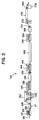
- Figure 2
- illustrates a schematic diagram of a side view of the draw line operation of the present invention from drawing to crimping continuous filaments in the form of a tow.
- Referring now to the accompanying drawings and initially to Figure 1, a conventional PET processing line for drawing and heat setting filamentary tow, which the present invention seeks to improve, is depicted schematically and indicated generally by
reference numeral 10. The processing line comprises a series of machine units arranged in alignment with one another for transport of a tow sequentially from one machine to the next. - Basically, tow 15 from storage cans or other suitable sources of tow supply (not shown) is initially delivered to a pretensioning-stand 12 having a series of driven cylindrical rolls 14 arranged alternatingly along upper and lower horizontal lines along the lengthwise extent of a
central frame 16 for travel of thetow 15 in a serpentine path in engagement with the periphery of each upper and lower row in sequence, whereby the multiple rolls 14 collectively establish an initial tensioning point in theprocessing line 10 preliminary to downstream drawing of thetow 15. - Two
drawstands 18, 20 are disposed at a downstream spacing from avat 17 and from one another. Eachdrawstand 18, 20 similarly comprises a centralupstanding frame 22 from which multiple cylindrical rolls cantilever outwardly extend alternatingly along upper and lower horizontal lines for travel of thetow 15 in a manner along a serpentine path peripherally about eachroll 24 in sequence, whereby the twodrawstands 18, 20 establish additional tensioning points along theprocessing line 10. Avat 17 containing a predrawing fluid, preferable a water-based emulsion, is disposed between the pretensioning-stand 12 and the drawstand 18, for application to thetow 15 before entering the first drawstand 18. The fluid aids in processing the tow e.g., reduced broken fils. A series of rolls 26 are mounted at the entrance of thevat 17 and also within thevat 17 below the fluid level to direct the travel of thetow 15 for immersion in the bath. At the end of thevat 17 are a pair of conventional nip rolls 28 to squeeze the excess fluid from the tow. Afirst fluid chest 30, basically constructed as an enclosed tunnel containing warm water sprays, is situated between the twodrawstands 18, 20 to apply hot water to thetow 15. The hot water is sufficient to heat the tow approximately to its glass transition temperature. Anotherfluid chest 32 is disposed at the down stream side of thesecond drawstand 20 but operates at a higher temperature than thefirst fluid chest 30. Typically, the second fluid chest applies steam to thetow 15 while traveling through the interior of the chest, to heat the tow above its glass transition temperature. - A
calender frame 34 is located immediately downstream of thesecond fluid chest 32 and basically comprises a relatively massive structure having a plurality of large-diameter rolls 38, cantilevered outwardly alternatingly along upper and lower horizontal lines for serpentine travel of thetow 15 peripherally about therolls 38 in sequence, in like manner to that previously described with respect to the pretensioning stand 12 and thedrawstands 18, 20. The cylindrical periphery of eachcalender roll 38, which is several times larger than the diameters of the rolls employed indraw frames 18, 20 or in the pretensioning stand 12, is heated from the interior by any suitable means, to a sufficient temperature (selected according to the physical characteristics of thetow 15, its traveling speed, residence time on the rolls, and other known variables) to heat-set the tow while it remains under tension. Due to the configuration of therolls 38 in thecalender frame 34, each side of thetow 15, which is in ribbon form, is heated to about 180-205° C for typically polyethylene terephthalate fiber. Other polymers of course, have different Tg's and require different heat setting ranges. - Immediately downstream of the
calender frame 34, is aquench stand 40 having sequentialcantilevered rolls 44 extending outwardly therefrom, to cool tow 15 sufficiently below the heat setting temperature thereby stabilizing the physical properties of the tow. From thequench stand 40, the tow progresses to spraystand 46 in which a spray (not shown) of suitable finishing composition is applied to thetow 15 to enhance subsequent crimping of the filaments of the tow. - The
tow 15, still remaining in its ribbon-like form is too thin to process for conventional crimping apparatus. Accordingly, astacker 48 positioned downstream from thefinish spray stand 46 is employed to stack the tow so that it is both narrower and thicker. Thestacker frame 48 comprises a plurality ofrolls 50 arranged and shown in Figure 1 to define separate travel paths by which the divided portions of thetow 15 can be directed to travel along independent paths. Therolls 50 define the different paths each being generally in converging relation with one another to direct the divided portions of thetow 15 to rolls 51 near the exit row of thestacker 48 at which the divided portions of thetow 15 are reassembled atop one another to form a thicker narrower towband. - The
tow 15 is delivered from thestacker frame 48 to a so-calleddancer frame 52 which serves as a "slack" take-up device to provide constant tension to the downstream crimper. Thedancer frame 52 has entrance andexit third roll 58 is vertically movable to take up tension fluctuations in thetow 15, to insure that the tow is delivered downstream to the crimper at substantially constant tension. Next, thetow 15 is transported from the dancer frame 52 through a steam atmosphere in a tunnel-like steam chest 60 to heat the tow to greater than its glass transition temperature, about 90°C for drawn polyethylene terephthalate, to insure that thetow 15 will maintain its crimp nature when it runs through the crimper. From thesteam chest 60 the tow is delivered to thecrimper 62 which is conventionally known to impart crimp or texture to the tow. Crimper 62 may be a so-called stuffer box, a gear crimping unit, or other suitable alternative device well known in the industry, If staple filaments are desired, then downstream of thecrimper 62 thetow 15 is typically dried and cut to staple lengths and collected in bale form for delivery to a conventional spinning operation for manufacture of spun yarn. - The draw line of Figures 1 is typically for polyester fibers. Polyester fibers include homopolymers of polyethylene terephthalate, polybutylene terephthalate, polypropylene terephthalate, and polyethylene naphthalate. Polyester fibers also include copolymers based on polyethylene terephthalate, such as polyethylene terephthalate isophthalate, polyethylene terephthalate adipate, or polyethylene terephthalate succinate, etc.; or copolymers based on polybutylene terephthalate such as polybutylene terephthalate adipate, polybutylene therephthalate succinate, etc.; or copolymers based on polypropylene terephthalate such as polypropylene terephthalate adipate, or polypropylene terephthalate succinate, etc.; or copolymers based on polyethylene naphthalate, such as polyethylene naphthalate isophthalate, polyethylene naphthalate adipate, polyethylene naphthalate succinate, or a mixture of any 2 or more of the above.
- As described previously while the
polyester processing line 10 represents an effective structure and methodology under the current state of the art for drawing, heat setting, and crimping of continuous synthetic filaments, the overall structure is quite massive and very expensive, due in a large part to the size required of thecalender frame 34. Thecalender frame 34 must be quite massive as the tow exerts tons of force on each roll and the residence time must be sufficient to heat the tow sufficient to "lock-in" the physical properties, while the tow is still under tension. Heating the tow to its heat setting temperature imposes strict limitations on the traveling speed at which thetow 15 can be processed. Generally a residence time of approximately 5 seconds is required to heat a tow having a density of 75,000 denier/per inch of width. The massive structural requirements of theframe 34 and the bearing structures therein to support therolls 38 against deflection, in order to satisfactorily apply heat uniformly throughout theentire tow 15 to both sides of the constituent filaments, can cost as much as 1/3 the cost of theentire line 10. - Fundamentally, the present invention substantially overcomes these difficulties and disadvantages and can run with a constant denier per inch of width far thicker (150,000 denier per inch of width of the tow or greater) than what is conventionally known with the apparatus of Figure 1 (75,000 denier per inch of width of the tow prior to the stacker).
- With reference to Figure 2, the present invention will be explained as follows. A synthetic fiber draw line of the present invention is generally indicated at 110. Generally, many small tows from a source such as tall containers are gathered into a single tow typically 3 million denier or greater and enter the
draw line 110 by means of thepretensioning device 112 having a series ofrolls 114 which serve to place a slight amount of tension on thetow 115 so that all wrinkles, tangles, and bunched-up fibers are in a ribbon-like shape. This is accomplished by positioning thetow 115 around therolls 114 in a serpentine path as is conventionally known in the art. Upon exit from thepretensioning device 114, the tow proceeds to adip bath 117 which has a fiber lubricating fluid, which is generally water soluble, and serves to wet each individual filament so that as the tow is further processed, the filaments do not abrade one another.Rolls 126 guide the tow into the dip bath and provide a path for the tow to travel below the liquid level in thedip tank 117. At the end of the dip bath, are a pair of nip rolls 128 to squeeze the excessive fluid from the tow so that the excessive liquid does not wet theentire draw line 110. - At this
stage tow 115 is in a flat ribbon-like shape and enters thestacker 130 having a plurality ofrolls 132 designed to split the tow into several distinct segments and stack those segments vertically upon one another such that the tow is now in the shape of a thick ribbon about 1/2 (or less) as wide as what originally entered the stacker. From thestacker 130, the tow enters the first draw stage comprising first draw rollers, a spray bath and second rollers. The first draw stand 134 comprised of the series ofrolls 136. Next, the filament tow enters a spray bath of 138 at an elevated temperature up to about 90°C for PET. Although a spray bath is shown, any suitable heating means is acceptable, such as a heated liquid bath, a steam chest, electromagnetic radiation, etc. From the spray bath the tow enters the nip rolls 139 designed to remove excess moisture from the tow, and then enters thesecond draw frame 144 having a plurality ofrolls 146. Therolls 146 have a circumferential velocity between 2 and 6 times faster than the circumferential velocity of therolls 136 in thefirst draw stand 134. This differential in velocity causes the fibers to stretch 2 to 6 times their original length. The tow now enters the final draw and heat setting stage to further draw and orient the tow to a degree higher than can be achieved by the first draw stage, and to heat set the tow in the oriented condition while it is still under tension. Optionally, the final draw and heat setting can be accomplished in separate steps as is conventionally known. The final draw and heatset stage comprisesroll stand 144,heating chamber 148, and rollstand 154. Therollers 156 on stand 145 are operated at about 1.1X to 2.5X times the speed ofrollers 146 on the precedingstand 144 in order to impart the final, high tension orientation of thetow 15. At least part of this final stretch occurs inchamber 148 which is operated at an elevated temperature in the range from about 100°C to about 200°C or greater. - The drawing and heat setting stage operates at a tow density of 150,000 denier per inch of width of tow or more. This is considerably greater than the practice of the prior art. The high density allows all the rollers to be considerably shorter in length, reducing the bending loads on the rollers and drawstands. The reduced loadings allow the equipment to be of lighter and less expensive construction.
- In order to heat the high-density tow,
chamber 148 must employ one or more heating methods which allow the heat to penetrate to the interior of the tow, as opposed to heating only the surface and relying on simple conduction. Such penetrating heating methods include electromagnetic radiation such as microwave or infrared, heated liquid baths and sprays, and forced flow of hot gases through the tow. Particularly suitable are methods which employ condensation of saturated vapor onto the tow, and especially condensation from pressurized vapors. The pressure provides a means for penetration of the vapors to the interior of the porous tow. - At the high temperatures of
chamber 148, crystallization of the polymer occurs while it is still under the high tensions of the final draw stage. This provides a means for "locking in" the oriented structure of the fibers, to provide desirable properties of high modulus and low shrinkage in the final product. After the tow is heat set inchamber 148 it passes onto theunheated rollers 156 ofdrawstand 154 for quenching the tow. The tow temperature is decreased to a point below the glass transition temperature of the polymer before the tension is released, so that the highly oriented structure is retained. - From the draw stand 154 the tow enters the finishing
chamber 168 havingrolls 170 in which a liquid coating is applied to the tow for ease of processing, or to apply a surface treatment to the tow filaments to yield particular characteristics. Conventional finishes are well known in the industry. After the finish chamber, the tow enters into asteam chest 176 by first traversing through a take-up roll stand 172 which is similar todancer frame 52 of Figure 1. Thesteam chest 176 quickly elevates the temperature of the tow for the same purpose assteam chest 60 in Figure 1. The tow enters thecrimper 178 by means of a pair of conventional nip rolls 180. Thecrimper 178 can be the stuffer box type or any conventional equipment capable of handling a tow of at least 150,000 denier per inch. Such apparatus is well known. - In operation, a tow of at least 3 million denier, collected from several spinning sources, or from a plurality of tow cans (not shown) enter a
pretensioning device 112 havingrolls 114 designed to straighten the individual filaments making up the ribbon-like shaped tow. Upon exit from thepretensioning device 112, thetow 115 enters the dip bath designed to supply a bit of moisture to the tow thus making it more processable (reducing the fiber to fiber abrasion). Typically, the dip bath applies an aqueous solution or solvent, at approximately ambient temperature (room temperature in most cases). The tow then enters thestacker 130 where the tow is plied upon one another to create an overall tow about 1/2 (or less) as wide and about 3 times thicker. After the stacker, thetow 115 enters the first draw frame in which therolls 136 typically have a circumferential velocity in the range of 50 mpm (meters per minute) to 200 mpm. Thespray bath 138 serves to heat the tow to at least above the first glass transition temperature of the polyester (which for amorphous polyethylene terephthalate is approximately 70°C). The tow then enters thesecond draw frame 144 and follows a serpentine path whereby the rolls of the second draw frame rotate at a circumferential velocity between the range of 100 mpm and 400 mpm. Because of the difference in rotational speeds, and heating the fiber in thespray bath 138, the tow draws between 2.0 and 4.0 times its original length in thespray bath 138. For polyester type polymeric fibers the total draw ratio is generally between 2 and 6 times its original length. For other polymeric fibers the total draw may be between 2 and 10 times its original length, depending on the type of polymer. - After the first draw, the tow is typically drawn again to further increase the physical properties. The drawing must occur at an elevated temperature, and this is provided in
heating chamber 148. In prior practice, it has been common to separate the final drawing and the heat setting stages, with the heat setting typically accomplished on heated rollers following the draw zone. In the present invention, it is preferred to combine the final drawing and the heat setting in one device. This simplifies the equipment, and also ensures that heat setting occurs at maximum orientation. After heatsetting it is important not to allow the tension to relax until the temperature is reduced to about the glass transition temperature or below of the polymeric fiber or else some of the orientation could be lost. It is the function ofdrawstand 154 not only to provide motive power for the final stretching of the towband, but also to provide for cooling of the tow after it exits fromheated chamber 148 before tension is released. For this purpose, therolls 156 may be provided with means for cooling such as internal circulation of cooling water or external fans which blow air over the tow. - After quenching, the tow is conventionally treated to a finish composition, heated sufficient to introduce the tow to a crimper, and crimped to provide the tow with "bulking" characteristics as is conventionally known. The tow then may be wound by winders (not shown) on a spindle (also not shown) and sold, or the tow exiting the crimper may be cut into staple lengths by conventional equipment (not shown) well known to those skilled in the art and baled and sold as staple fibers.
Claims (15)
- A process for the production of polymeric fibers in the form of a tow, comprising: drawing said tow between 2 to 6 times its original length, heat setting said tow under tension; and crimping said tow to provide bulking, whereby said tow, after drawing, has a nominal constant denier per inch of width.
- The process of claim 1, wherein said tow before being drawn has a denier of at least 3 million.
- The process of claim 1 or 2, wherein said polymeric fiber, after drawing has a denier per inch width of 150,000 or more.
- A process for the production of polymeric fibers in the form of a tow, comprising: drawing said tow between 2 to 6 times its original length and heat setting said tow under tension, whereby said tow, after drawing, has a denier per inch of width of 150,000 or more.
- The process of any one or more of claims 1 to 4, wherein said polymeric fiber is selected from the group consisting of homopolymers and copolymers of polyethylene terephthalete; homopolymers and copolymer of polypropylene terephthalate; homopolymers and copolymers of polybutylene terephthalate; and homopolymers and copolymers of polyethylene naphthalate.
- The process of any one or more of claims 1 to 5, wherein said heat setting is accomplished by pressurized gas which condenses on the tow, electromagnetic radiation, or heated liquid bath.
- The process of claim 6, wherein said electromagnetic radiation is infrared radiation or microwave radiation.
- The process of claim 6, wherein said heated liquid bath comprises heated oil or any liquid which does not evaporate at temperature below about 200 °C.
- The process of claim 8, wherein said heated oil is mineral oil.
- The process of claim 5, wherein said pressurized gas is steam (H2O) which condenses on the tow.
- The process of any one or more of claims 1 to 9, wherein said tow is quenched after said heat setting step.
- Apparatus for the production of polyester fibers in the form of a tow, comprising: a stacker for stacking a tow; a first drawstand having a plurality of rolls; said tow forming a serpentine path around said rolls, a second drawstand having a plurality of second rolls, said tow forming a serpentine path around said second rolls, a heating means for heating the tow between said first draw stand and said second draw stand, and a heat setting device comprising one or more of a heated liquid bath, a pressurized gas device which condenses the gas on the tow, or electromagnetic radiation, for heat setting the tow after it has been drawn, the tow having a constant denier per inch of width.
- The apparatus of claim 12, wherein said plurality of rolls of said first and second draw stands are less than 1 meter in length.
- The apparatus of claim 12 or 13, including a crimper positioned after said heat setting device for crimping the tow.
- The apparatus of claim 14, including a cutter apparatus positioned after said crimper for cutting the tow into staple lengths.
Applications Claiming Priority (2)
| Application Number | Priority Date | Filing Date | Title |
|---|---|---|---|
| US356138 | 1999-07-19 | ||
| US09/356,138 US6210622B1 (en) | 1999-07-19 | 1999-07-19 | Process of making polymeric fibers |
Publications (2)
| Publication Number | Publication Date |
|---|---|
| EP1072704A1 true EP1072704A1 (en) | 2001-01-31 |
| EP1072704B1 EP1072704B1 (en) | 2007-12-05 |
Family
ID=23400286
Family Applications (1)
| Application Number | Title | Priority Date | Filing Date |
|---|---|---|---|
| EP00112059A Expired - Lifetime EP1072704B1 (en) | 1999-07-19 | 2000-06-03 | Apparatus and method for drawing, heat setting, and crimping of filamentary material |
Country Status (14)
| Country | Link |
|---|---|
| US (1) | US6210622B1 (en) |
| EP (1) | EP1072704B1 (en) |
| KR (1) | KR100732597B1 (en) |
| CN (1) | CN100347365C (en) |
| BR (1) | BR0002939A (en) |
| DE (1) | DE60037295T2 (en) |
| EG (1) | EG22324A (en) |
| ES (1) | ES2296584T3 (en) |
| ID (1) | ID26478A (en) |
| MX (1) | MXPA00007050A (en) |
| MY (1) | MY125386A (en) |
| SA (1) | SA00210171B1 (en) |
| TR (1) | TR200002092A3 (en) |
| TW (1) | TW541372B (en) |
Cited By (3)
| Publication number | Priority date | Publication date | Assignee | Title |
|---|---|---|---|---|
| WO2008022947A1 (en) * | 2006-08-19 | 2008-02-28 | Oerlikon Textile Gmbh & Co. Kg | Method and apparatus for producing staple fibres from a crimped sliver |
| RU2421554C2 (en) * | 2006-10-21 | 2011-06-20 | Ёрликон Текстиле Гмбх Унд Ко. Кг | Method and device to processing yarn fibre |
| EP1990393B1 (en) * | 2007-05-11 | 2013-05-15 | Coroplast Fritz Müller GmbH & Co. KG | Hand-tearable fabric-adhesive tape |
Families Citing this family (17)
| Publication number | Priority date | Publication date | Assignee | Title |
|---|---|---|---|---|
| BR0007494B1 (en) * | 1999-01-12 | 2010-12-28 | non-woven fabric, method of forming the same and apparatus for laminating the same. | |
| JP3534108B2 (en) * | 2002-09-17 | 2004-06-07 | 株式会社山梨ティー・エル・オー | Method and apparatus for producing drawn filament and ultrafine filament with high molecular orientation |
| US7585445B2 (en) * | 2002-09-26 | 2009-09-08 | Saurer Gmbh & Co., Kg | Method for producing high tenacity polypropylene fibers |
| US7578957B2 (en) | 2002-12-30 | 2009-08-25 | E. I. Du Pont De Nemours And Company | Process of making staple fibers |
| ITMI20081112A1 (en) * | 2007-08-02 | 2009-02-03 | Oerlikon Textile Gmbh & Co Kg | DEVICE TO ENRICH BRANCHES OF SYNTHETIC FIBERS |
| MY156861A (en) * | 2010-05-11 | 2016-04-15 | Cytec Tech Corp | Apparatus and methods for spreading fiber bundles for the continuous production of prepreg |
| KR101135450B1 (en) * | 2010-11-25 | 2012-04-16 | 송종복 | Method for producing staple fiber for pad used pet micro miracle(m2) made by direct spining and pad used thereof |
| US9776369B2 (en) * | 2013-03-15 | 2017-10-03 | Shimano American Corp. | Heated liquid tapered line production device and method |
| CN104328563B (en) * | 2014-09-23 | 2016-09-14 | 张家港市荣昌涤纶毛条有限公司 | Terylene tow first break draft production line |
| CN104562247B (en) * | 2015-01-22 | 2016-09-14 | 张家港市荣昌涤纶毛条有限公司 | Production Technology of Polyester Radiation-proof Top |
| CN104562248B (en) * | 2015-01-22 | 2016-09-14 | 张家港市荣昌涤纶毛条有限公司 | The production technology of terylene conductive wool top |
| EP3387175B1 (en) * | 2015-12-11 | 2022-09-21 | Kimberly-Clark Worldwide, Inc. | Method for forming porous fibers |
| CN105437305B (en) * | 2015-12-29 | 2017-07-14 | 重庆市大通茂纺织科技有限公司 | Edge cutting machine including paving device |
| CN108431310A (en) | 2015-12-31 | 2018-08-21 | Ut-巴特勒有限公司 | Method for producing carbon fibers from multipurpose commercial fibers |
| KR102314309B1 (en) * | 2019-10-08 | 2021-10-20 | 김대식 | Filter for Ciga type Electronic Cigarette |
| CN117604668B (en) * | 2023-12-12 | 2026-01-06 | 蓝星(成都)新材料有限公司 | A high-modulus aramid 1414 fiber for optical cables and its preparation method |
| US12312710B1 (en) * | 2024-01-12 | 2025-05-27 | Jiangsu Ganghong Fiber Co., Ltd. | Method for preparing direct melt-spun high-viscosity PBAT/low-viscosity pet two-component elastic fiber and high-viscosity PBAT polymerization reactor |
Citations (8)
| Publication number | Priority date | Publication date | Assignee | Title |
|---|---|---|---|---|
| US2918346A (en) * | 1956-08-07 | 1959-12-22 | Du Pont | Process of orienting a dense tow of polymeric ester filaments by two step hot aqueous bath treatments |
| GB1219154A (en) * | 1968-06-17 | 1971-01-13 | Du Pont | Process for drawing and crimping a tow of asymmetrically birefringent polyester filaments |
| US3894135A (en) * | 1971-10-06 | 1975-07-08 | Zimmer Ag | Process for stretching a cable of polyester threads |
| US4105740A (en) * | 1973-12-26 | 1978-08-08 | Toyo Boseki Kabushiki Kaisha | Process for the production of polyester fiber |
| US4112668A (en) * | 1976-10-04 | 1978-09-12 | Monsanto Company, St. Louis, Missouri | Method for treating polyester filaments |
| EP0493050A1 (en) * | 1990-12-21 | 1992-07-01 | E.I. Du Pont De Nemours And Company | A process and apparatus for tow cross-section measurement and control |
| EP0540062A2 (en) * | 1988-07-15 | 1993-05-05 | E.I. Du Pont De Nemours And Company | Process and apparatus for spinning and drawing monofilaments with high tenacity and high tensile uniformity |
| EP0935016A1 (en) * | 1998-02-04 | 1999-08-11 | ARTEVA TECHNOLOGIES S.à.r.l. | Calendering apparatus and method for heating traveling multifilament tow |
Family Cites Families (21)
| Publication number | Priority date | Publication date | Assignee | Title |
|---|---|---|---|---|
| BE631629A (en) | 1962-04-27 | |||
| US3567817A (en) | 1965-02-23 | 1971-03-02 | Monsanto Co | Polyester tow preheating and drawing process |
| US3364294A (en) * | 1965-09-20 | 1968-01-16 | Monsanto Co | Filament orientation process |
| US3816486A (en) | 1969-11-26 | 1974-06-11 | Du Pont | Two stage drawn and relaxed staple fiber |
| JPS5241370B2 (en) | 1973-09-14 | 1977-10-18 | ||
| JPS5132816A (en) | 1974-09-10 | 1976-03-19 | Asahi Chemical Ind | ENSHINHOHO |
| JPS5237826A (en) * | 1975-09-17 | 1977-03-24 | Teijin Ltd | Process for producing crimped tows |
| JPS5345417A (en) | 1976-10-06 | 1978-04-24 | Asahi Chem Ind Co Ltd | Heat drawing process for monofilament |
| SU594220A1 (en) | 1977-03-09 | 1978-02-25 | Ленинградское Машиностроительное Объе Динение Им.К.Маркса | Method of making cord threads |
| SU958529A1 (en) | 1980-11-19 | 1982-09-15 | Всесоюзный Научно-Исследовательский Институт Машин Для Производства Синтетических Волокон | Chamber for heating continuously moving filaments at oriented drawing |
| US4704329A (en) | 1984-03-16 | 1987-11-03 | E. I. Du Pont De Nemours And Company | Annealed polyester filaments and a process for making them |
| JPS63135516A (en) | 1986-11-19 | 1988-06-07 | Mitsubishi Rayon Co Ltd | Polyester fiber having high strength |
| SU1700116A1 (en) | 1989-08-07 | 1991-12-23 | Научно-Производственное Объединение "Химтекстильмаш" | Method of producing monofilaments of thermoplastic polymers |
| DE69030668T2 (en) * | 1989-08-17 | 1997-11-27 | Commonwealth Scientific And Industrial Research Organisation, Campbell | STRETCH OF STACKED FIBERS |
| US5104969A (en) | 1989-10-20 | 1992-04-14 | E. I. Du Pont De Nemours And Company | Low shrinkage, high tenacity poly(epsilon-caproamide) yarn and process for making same |
| US5073322A (en) * | 1990-08-29 | 1991-12-17 | E. I. Du Pont De Nemours And Company | Processing of ethylene terephthalate/hexahydroterephthalate copolymer filaments |
| US5175239A (en) | 1990-12-27 | 1992-12-29 | E. I. Du Pont De Nemours And Company | Process for making para-aramid fibers having high tenacity and modulus by microwave annealing |
| DE4215015A1 (en) | 1992-05-12 | 1993-11-18 | Amann & Soehne | Stretching process |
| US5407620A (en) * | 1993-06-23 | 1995-04-18 | Basf Corporation | One-step process for the manufacture of twisted nylon yarn |
| DE19519882A1 (en) * | 1995-05-31 | 1996-12-12 | Hoechst Ag | Method of treating a cable of synthetic filaments and method of producing cables of uniformly crimped fibers with a high initial modulus |
| KR0133617B1 (en) * | 1995-12-28 | 1998-04-24 | 김준웅 | Process for manufacturing polyester single fiber for non woven fabric |
-
1999
- 1999-07-19 US US09/356,138 patent/US6210622B1/en not_active Expired - Fee Related
-
2000
- 2000-03-06 TW TW089103919A patent/TW541372B/en not_active IP Right Cessation
- 2000-04-12 CN CNB001065599A patent/CN100347365C/en not_active Expired - Fee Related
- 2000-04-19 KR KR1020000020559A patent/KR100732597B1/en not_active Expired - Fee Related
- 2000-06-03 EP EP00112059A patent/EP1072704B1/en not_active Expired - Lifetime
- 2000-06-03 DE DE60037295T patent/DE60037295T2/en not_active Expired - Fee Related
- 2000-06-03 ES ES00112059T patent/ES2296584T3/en not_active Expired - Lifetime
- 2000-06-26 SA SA00210171A patent/SA00210171B1/en unknown
- 2000-07-01 EG EG20000860A patent/EG22324A/en active
- 2000-07-11 ID IDP20000580A patent/ID26478A/en unknown
- 2000-07-17 MY MYPI20003268 patent/MY125386A/en unknown
- 2000-07-18 MX MXPA00007050A patent/MXPA00007050A/en unknown
- 2000-07-18 BR BR0002939-4A patent/BR0002939A/en not_active Application Discontinuation
- 2000-07-18 TR TR2000/02092A patent/TR200002092A3/en unknown
Patent Citations (8)
| Publication number | Priority date | Publication date | Assignee | Title |
|---|---|---|---|---|
| US2918346A (en) * | 1956-08-07 | 1959-12-22 | Du Pont | Process of orienting a dense tow of polymeric ester filaments by two step hot aqueous bath treatments |
| GB1219154A (en) * | 1968-06-17 | 1971-01-13 | Du Pont | Process for drawing and crimping a tow of asymmetrically birefringent polyester filaments |
| US3894135A (en) * | 1971-10-06 | 1975-07-08 | Zimmer Ag | Process for stretching a cable of polyester threads |
| US4105740A (en) * | 1973-12-26 | 1978-08-08 | Toyo Boseki Kabushiki Kaisha | Process for the production of polyester fiber |
| US4112668A (en) * | 1976-10-04 | 1978-09-12 | Monsanto Company, St. Louis, Missouri | Method for treating polyester filaments |
| EP0540062A2 (en) * | 1988-07-15 | 1993-05-05 | E.I. Du Pont De Nemours And Company | Process and apparatus for spinning and drawing monofilaments with high tenacity and high tensile uniformity |
| EP0493050A1 (en) * | 1990-12-21 | 1992-07-01 | E.I. Du Pont De Nemours And Company | A process and apparatus for tow cross-section measurement and control |
| EP0935016A1 (en) * | 1998-02-04 | 1999-08-11 | ARTEVA TECHNOLOGIES S.à.r.l. | Calendering apparatus and method for heating traveling multifilament tow |
Cited By (4)
| Publication number | Priority date | Publication date | Assignee | Title |
|---|---|---|---|---|
| WO2008022947A1 (en) * | 2006-08-19 | 2008-02-28 | Oerlikon Textile Gmbh & Co. Kg | Method and apparatus for producing staple fibres from a crimped sliver |
| CN101506417B (en) * | 2006-08-19 | 2011-11-09 | 欧瑞康纺织有限及两合公司 | Method and apparatus for producing staple fibers from texturized fiber strands |
| RU2421554C2 (en) * | 2006-10-21 | 2011-06-20 | Ёрликон Текстиле Гмбх Унд Ко. Кг | Method and device to processing yarn fibre |
| EP1990393B1 (en) * | 2007-05-11 | 2013-05-15 | Coroplast Fritz Müller GmbH & Co. KG | Hand-tearable fabric-adhesive tape |
Also Published As
| Publication number | Publication date |
|---|---|
| MY125386A (en) | 2006-07-31 |
| US6210622B1 (en) | 2001-04-03 |
| KR20010066770A (en) | 2001-07-11 |
| DE60037295T2 (en) | 2008-11-27 |
| TR200002092A2 (en) | 2001-02-21 |
| CN1281065A (en) | 2001-01-24 |
| KR100732597B1 (en) | 2007-06-27 |
| CN100347365C (en) | 2007-11-07 |
| MXPA00007050A (en) | 2002-06-04 |
| EG22324A (en) | 2002-12-31 |
| TR200002092A3 (en) | 2001-02-21 |
| EP1072704B1 (en) | 2007-12-05 |
| ID26478A (en) | 2001-01-11 |
| ES2296584T3 (en) | 2008-05-01 |
| DE60037295D1 (en) | 2008-01-17 |
| BR0002939A (en) | 2001-01-30 |
| SA00210171B1 (en) | 2006-05-20 |
| TW541372B (en) | 2003-07-11 |
Similar Documents
| Publication | Publication Date | Title |
|---|---|---|
| EP1072704B1 (en) | Apparatus and method for drawing, heat setting, and crimping of filamentary material | |
| CN102016138B (en) | Method for melt-spinning, drawing, and winding up a multifilament, and apparatus for carrying out said method | |
| US4035879A (en) | Apparatus for producing texturized yarns | |
| US4237187A (en) | Highly oriented, partially drawn, untwisted, compact poly(ε-caproamide) yarn | |
| US2934400A (en) | Process of manufacturing fibers of polyethylene terephthalate | |
| US5340523A (en) | Improved method of incrementally drawing fibers | |
| US6477828B1 (en) | Method of false twist texturing a synthetic yarn to a crimped yarn | |
| US3975484A (en) | Manufacture of crimped polyamide filaments yarn | |
| CN1323198C (en) | Method and apparatus for melt spinning and cutting of tow | |
| CN1328423C (en) | Method for producing highly stable polypropylene fibres | |
| US4042662A (en) | Continuous melt spinning and drawing of nylon 6 yarn, while reducing the liveliness of the yarn | |
| US3949041A (en) | Method for texturing synthetic filament yarn | |
| US6168747B1 (en) | Calendering apparatus and method for heating a traveling multi-filament tow | |
| US4030169A (en) | Method and apparatus for treating yarn | |
| CN1065006C (en) | Method and apparatus for spinning synthetic multi-filament yarn | |
| US4980957A (en) | Improved method of incremently drawing fibers | |
| US5643515A (en) | Method and apparatus for producing stretched yarns | |
| US3761556A (en) | The manufacture of bulked yarn | |
| KR19990044083A (en) | Manufacturing method of high strength high shrink polyamide 66 filament yarn | |
| US7386925B2 (en) | Process and apparatus for the production of artificial grass | |
| GB2319745A (en) | Spinning machine for oriented multifilament yarns | |
| GB1196586A (en) | Jet Drawing of Conjugate Filaments | |
| US6203743B1 (en) | Heat setting a tow of synthetic fibers using high pressure dewatering nip | |
| US3955351A (en) | Production of bulked yarns | |
| JPS60209013A (en) | Preparation of polyester yarn |
Legal Events
| Date | Code | Title | Description |
|---|---|---|---|
| PUAI | Public reference made under article 153(3) epc to a published international application that has entered the european phase |
Free format text: ORIGINAL CODE: 0009012 |
|
| AK | Designated contracting states |
Kind code of ref document: A1 Designated state(s): DE ES FR GB IT |
|
| AX | Request for extension of the european patent |
Free format text: AL;LT;LV;MK;RO;SI |
|
| 17P | Request for examination filed |
Effective date: 20010731 |
|
| AKX | Designation fees paid |
Free format text: DE ES FR GB IT |
|
| RAP1 | Party data changed (applicant data changed or rights of an application transferred) |
Owner name: INVISTA TECHNOLOGIES S.AE.R.L. |
|
| 111Z | Information provided on other rights and legal means of execution |
Free format text: DEESFRGBIT Effective date: 20040925 |
|
| 17Q | First examination report despatched |
Effective date: 20070103 |
|
| GRAP | Despatch of communication of intention to grant a patent |
Free format text: ORIGINAL CODE: EPIDOSNIGR1 |
|
| GRAS | Grant fee paid |
Free format text: ORIGINAL CODE: EPIDOSNIGR3 |
|
| GRAA | (expected) grant |
Free format text: ORIGINAL CODE: 0009210 |
|
| AK | Designated contracting states |
Kind code of ref document: B1 Designated state(s): DE ES FR GB IT |
|
| REG | Reference to a national code |
Ref country code: GB Ref legal event code: FG4D |
|
| REF | Corresponds to: |
Ref document number: 60037295 Country of ref document: DE Date of ref document: 20080117 Kind code of ref document: P |
|
| REG | Reference to a national code |
Ref country code: ES Ref legal event code: FG2A Ref document number: 2296584 Country of ref document: ES Kind code of ref document: T3 |
|
| REG | Reference to a national code |
Ref country code: GB Ref legal event code: 732E |
|
| ET | Fr: translation filed | ||
| PLBE | No opposition filed within time limit |
Free format text: ORIGINAL CODE: 0009261 |
|
| STAA | Information on the status of an ep patent application or granted ep patent |
Free format text: STATUS: NO OPPOSITION FILED WITHIN TIME LIMIT |
|
| PGFP | Annual fee paid to national office [announced via postgrant information from national office to epo] |
Ref country code: ES Payment date: 20080717 Year of fee payment: 9 Ref country code: DE Payment date: 20080612 Year of fee payment: 9 |
|
| 26N | No opposition filed |
Effective date: 20080908 |
|
| PGFP | Annual fee paid to national office [announced via postgrant information from national office to epo] |
Ref country code: IT Payment date: 20080627 Year of fee payment: 9 Ref country code: FR Payment date: 20080617 Year of fee payment: 9 |
|
| PGFP | Annual fee paid to national office [announced via postgrant information from national office to epo] |
Ref country code: GB Payment date: 20080604 Year of fee payment: 9 |
|
| REG | Reference to a national code |
Ref country code: GB Ref legal event code: 732E Free format text: REGISTERED BETWEEN 20090507 AND 20090513 |
|
| GBPC | Gb: european patent ceased through non-payment of renewal fee |
Effective date: 20090603 |
|
| REG | Reference to a national code |
Ref country code: FR Ref legal event code: ST Effective date: 20100226 |
|
| PG25 | Lapsed in a contracting state [announced via postgrant information from national office to epo] |
Ref country code: FR Free format text: LAPSE BECAUSE OF NON-PAYMENT OF DUE FEES Effective date: 20090630 |
|
| PG25 | Lapsed in a contracting state [announced via postgrant information from national office to epo] |
Ref country code: GB Free format text: LAPSE BECAUSE OF NON-PAYMENT OF DUE FEES Effective date: 20090603 |
|
| PG25 | Lapsed in a contracting state [announced via postgrant information from national office to epo] |
Ref country code: DE Free format text: LAPSE BECAUSE OF NON-PAYMENT OF DUE FEES Effective date: 20100101 |
|
| REG | Reference to a national code |
Ref country code: ES Ref legal event code: FD2A Effective date: 20090604 |
|
| PG25 | Lapsed in a contracting state [announced via postgrant information from national office to epo] |
Ref country code: ES Free format text: LAPSE BECAUSE OF NON-PAYMENT OF DUE FEES Effective date: 20090604 |
|
| PG25 | Lapsed in a contracting state [announced via postgrant information from national office to epo] |
Ref country code: IT Free format text: LAPSE BECAUSE OF NON-PAYMENT OF DUE FEES Effective date: 20090603 |