EP1071973B1 - Methods for connecting optical fibers to integrated optical waveguides - Google Patents
Methods for connecting optical fibers to integrated optical waveguides Download PDFInfo
- Publication number
- EP1071973B1 EP1071973B1 EP99920625A EP99920625A EP1071973B1 EP 1071973 B1 EP1071973 B1 EP 1071973B1 EP 99920625 A EP99920625 A EP 99920625A EP 99920625 A EP99920625 A EP 99920625A EP 1071973 B1 EP1071973 B1 EP 1071973B1
- Authority
- EP
- European Patent Office
- Prior art keywords
- laser beam
- waveguide
- abutment
- zone
- laser
- Prior art date
- Legal status (The legal status is an assumption and is not a legal conclusion. Google has not performed a legal analysis and makes no representation as to the accuracy of the status listed.)
- Expired - Lifetime
Links
Images


Classifications
-
- G—PHYSICS
- G02—OPTICS
- G02B—OPTICAL ELEMENTS, SYSTEMS OR APPARATUS
- G02B6/00—Light guides; Structural details of arrangements comprising light guides and other optical elements, e.g. couplings
- G02B6/24—Coupling light guides
- G02B6/255—Splicing of light guides, e.g. by fusion or bonding
- G02B6/2551—Splicing of light guides, e.g. by fusion or bonding using thermal methods, e.g. fusion welding by arc discharge, laser beam, plasma torch
-
- G—PHYSICS
- G02—OPTICS
- G02B—OPTICAL ELEMENTS, SYSTEMS OR APPARATUS
- G02B6/00—Light guides; Structural details of arrangements comprising light guides and other optical elements, e.g. couplings
- G02B6/24—Coupling light guides
- G02B6/26—Optical coupling means
- G02B6/30—Optical coupling means for use between fibre and thin-film device
Description
Preferably, the spot produced by the laser beam at the zone of
Claims (27)
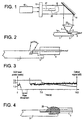
- A method for connecting an optical fiber (3) to an optical waveguide (1a) in a chip (1), comprising the steps ofcharacterised in that the spatial energy distribution of the laser beam is modified such that the central part of said distribution across the zone of abutment between the optical fiber and the waveguide is reduced with respect to the central part thereof at the laser output to avoid adverse melting of the optical fiber or bending of the waveguide.aligning the optical fiber with the waveguide;bringing the optical fiber and waveguide into abutment;emitting a laser beam from a laser (10); andirradiating a zone around the abutted optical fiber and waveguide with the laser beam, thereby fusing the optical fiber to the waveguide,
- The method according to claim 1, wherein the step of modifying said spatial energy distribution comprises disposing a shield (20) in the path of the laser beam upstream of said zone of abutment to eliminate a substantially central part of the laser beam while allowing a peripheral part thereof to pass.
- The method according to claim 2, wherein between 20% and 80% of the power of the laser beam is eliminated by the shield upstream of the zone of abutment between the optical fiber and the waveguide.
- The method according to claim 2, wherein about 50% of the power of the laser beam is eliminated by the shield.
- The method according to any preceding claim, wherein the step of irradiating the zone of abutment comprises focusing the laser beam substantially on the zone of abutment.
- The method according to any of claims 1 to 4, wherein the step of irradiating the zone of abutment comprises slightly defocusing the beam on said zone of abutment.
- The method according to any of claims 2 to 4, wherein the shield (20) is substantially cylindrical in shape and a long axis of the cylinder is arranged in the path of the laser beam with the axis aligned with a direction of propagation of the laser beam.
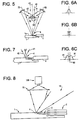
- The method according to claim 1, wherein the spatial energy distribution of the laser beam (40) is modified by splitting, upstream of said zone of abutment, the laser beam into a plurality of beams (41, 42) and directing the splitted beams towards said zone of abutment.
- The method according to claim 8, wherein said plurality of beams are slightly defocused at said zone of abutment.
- The method according to any preceding claim, wherein the spatial energy distribution is such that the amount of energy which irradiates the waveguide is greater than the amount which irradiates the optical fiber.
- The method according to any preceding claim, wherein said step of irradiating the zone of abutment comprises the laser beam at said zone of abutment having a diameter, further wherein the beam is offset with respect to a boundary between the optical fiber and the waveguide, towards the waveguide by a distance of about 5-20% of said diameter.
- The method according to any preceding claim, wherein, during irradiation of the zone of abutment, a force is applied between the optical fiber and the waveguide so as to move them closer together.
- The method according to claim 12, wherein said force causes a relative displacement less than or equal to about 50µm.
- The method according to any preceding claim, further comprising the step of forming a further connection between the optical fiber and the waveguide using a bonding substance (25).
- The method according to any preceding claim, wherein the laser power is at a first, relatively higher level during a first period of time during which a fusion joint is formed between the optical fiber and waveguide, and is at a lower level during a second period of time, subsequent to the first period of time, to allow a gradual cooling of the fusion joint.
- The method according to any preceding claim, wherein the waveguide is formed in a silica chip.
- The method according to any preceding claim, wherein the laser beam has a wavelength greater than 4µm.
- The method according to claim 17, wherein the laser is a CO2 laser.
- The method according to any preceding claim, wherein an extremity of the waveguide is positioned to within about ±1 µm with respect to the laser beam center at the zone of abutment.
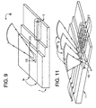
- A method of connecting a plurality of optical fibers (2) to a respective plurality of waveguides (1a) in a chip (1), comprising the steps ofcharacterised in that the laser beam is propagated through a diffractive optical element (140) to simultaneously produce a desired spatial laser energy distribution at the zone of abutment for each of the plurality of connections to avoid adverse melting of the optical fibers or bending of the waveguides.aligning the optical fibers with the respective waveguides;abutting the optical fibers to the respective waveguides;emitting a laser beam from a laser; andirradiating a zone around the abutted optical fibers and waveguides with the laser beam, thereby fusing the optical fibers to the respective waveguides;
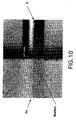
- The method of claim 20, wherein the spatial energy distribution of the laser beam on the chip has a two dimensional shape comprised of one of at least one rectangle, a series of squares, or a series of circles.
- The method of claim 20 or 21, wherein the diffractive optical element is positioned downstream from a focusing lens.
- The method of any of claims 20 to 22, wherein said diffractive optical element is used to focus said laser beam on said chip.
- The method of any of claims 20 to 23, wherein said laser beam has a wavelength equal to or greater than 4µm.
- The method of claim 24, where said laser is a CO2 laser.
- A method of connecting a plurality of optical fibers (2) to a respective plurality of waveguides (12) in a chip (1), comprising the steps of:characterised in that the laser beam is propagated to a beam scanner (17) and modified to scan over the zones of abutment between the optical fibers and the respective waveguides with a desired spatial energy distribution and repetition rate, whereby the plurality of zones of abutment are substantially heated simultaneously, and adverse melting of the optical fibers or bending of the waveguides is avoided.aligning the optical fibers and respective waveguides;abutting the optical fibers to the respective waveguides;emitting a laser beam from a laser; andirradiating a zone around the abutted optical fibers and waveguides with the laser beam, thereby fusing the optical fibers to the respective waveguides;
- The method of claim 26, wherein the beam is scanned with a repetition rate of between about 100Hz-10kHz.
Applications Claiming Priority (3)
| Application Number | Priority Date | Filing Date | Title |
|---|---|---|---|
| FR9804438A FR2777359B1 (en) | 1998-04-09 | 1998-04-09 | CONNECTION OF OPTICAL FIBER AND OPTICAL WAVEGUIDE BY MERGER |
| FR9804438 | 1998-04-09 | ||
| PCT/EP1999/002421 WO1999053351A1 (en) | 1998-04-09 | 1999-04-09 | Method for connecting optical fiber and optical waveguide |
Publications (2)
| Publication Number | Publication Date |
|---|---|
| EP1071973A1 EP1071973A1 (en) | 2001-01-31 |
| EP1071973B1 true EP1071973B1 (en) | 2003-09-24 |
Family
ID=9525053
Family Applications (1)
| Application Number | Title | Priority Date | Filing Date |
|---|---|---|---|
| EP99920625A Expired - Lifetime EP1071973B1 (en) | 1998-04-09 | 1999-04-09 | Methods for connecting optical fibers to integrated optical waveguides |
Country Status (10)
| Country | Link |
|---|---|
| US (1) | US6411759B1 (en) |
| EP (1) | EP1071973B1 (en) |
| JP (1) | JP2002511599A (en) |
| CN (1) | CN1295676A (en) |
| AU (1) | AU3814499A (en) |
| CA (1) | CA2327428A1 (en) |
| DE (1) | DE69911593D1 (en) |
| FR (1) | FR2777359B1 (en) |
| TW (1) | TW424165B (en) |
| WO (1) | WO1999053351A1 (en) |
Families Citing this family (25)
| Publication number | Priority date | Publication date | Assignee | Title |
|---|---|---|---|---|
| EP1174740A1 (en) * | 2000-07-21 | 2002-01-23 | Corning Incorporated | Method and apparatus for splicing optical fibers having different mode field diameters |
| EP1255139A1 (en) * | 2001-05-03 | 2002-11-06 | Corning Incorporated | Method and apparatus for splicing optical fibres |
| DE10127331B4 (en) * | 2001-05-22 | 2006-06-14 | Schott Ag | Method for connecting at least one optical fiber to a GRIN lens and filter module |
| TW552645B (en) * | 2001-08-03 | 2003-09-11 | Semiconductor Energy Lab | Laser irradiating device, laser irradiating method and manufacturing method of semiconductor device |
| GB0129286D0 (en) * | 2001-12-06 | 2002-01-23 | Optek Ltd | Improvements relating to the coupling of optical waveguides |
| SE522255C2 (en) * | 2002-02-26 | 2004-01-27 | Ericsson Telefon Ab L M | Apparatus and method for melting the ends of two optical fibers |
| DE10234946A1 (en) * | 2002-07-31 | 2004-02-19 | CCS Technology, Inc., Wilmington | Method and device for splicing optical fibers |
| GB0223361D0 (en) * | 2002-10-08 | 2002-11-13 | Council Cent Lab Res Councils | Optical micro sensor |
| US20040071404A1 (en) * | 2002-10-09 | 2004-04-15 | Masalkar Prafulla Jinendra | Apparatus for increasing directivity and lowering background light in tap detectors |
| US20050180695A1 (en) * | 2002-10-15 | 2005-08-18 | Sagitta Engineering Solutions Ltd. | Method and apparatus for planar lightwave circuits pigtailing |
| US20050135733A1 (en) * | 2003-12-19 | 2005-06-23 | Benoit Reid | Integrated optical loop mirror |
| US7263260B2 (en) * | 2005-03-14 | 2007-08-28 | Matsushita Electric Industrial Co., Ltd. | Low cost, high precision multi-point optical component attachment |
| US8217311B2 (en) * | 2006-09-12 | 2012-07-10 | Kilolambda Technologies Ltd. | Method for laser induced fusion pigtailing of optical fiber to optical waveguide |
| JP2008242012A (en) * | 2007-03-27 | 2008-10-09 | Mitsubishi Cable Ind Ltd | Laser guide optical fiber and laser guide equipped with the same |
| JP4682179B2 (en) * | 2007-11-19 | 2011-05-11 | 三菱電機株式会社 | Method and apparatus for welding resin material |
| CN107219628B (en) * | 2013-11-27 | 2020-05-01 | 奇跃公司 | Virtual and augmented reality systems and methods |
| JP6417710B2 (en) * | 2014-05-20 | 2018-11-07 | 住友電気工業株式会社 | Bending optical fiber manufacturing method |
| CN110045463B (en) * | 2018-01-15 | 2021-09-07 | 中国科学院上海光学精密机械研究所 | Connecting piece and method for optical fiber fusion |
| US10345533B1 (en) * | 2018-02-15 | 2019-07-09 | Corning Incorporated | Assemblies, optical connectors and methods of bonding optical fibers to substrates |
| US10746937B2 (en) * | 2018-02-15 | 2020-08-18 | Corning Incorporated | Assemblies, optical connectors and methods of bonding optical elements to substrates |
| US11701839B2 (en) * | 2018-06-14 | 2023-07-18 | Airbus Operations Gmbh | Method and system for joining two components of a meltable material |
| US11841535B2 (en) | 2018-07-06 | 2023-12-12 | O'fiberty Technologies Inc. | Method of fusion splicing optical fibers with lasers |
| US11808981B2 (en) | 2018-07-06 | 2023-11-07 | O'fiberty Technologies Inc. | Method of fusion splicing optical fibers with lasers |
| CN109954969B (en) * | 2019-03-29 | 2021-04-13 | 中国航空制造技术研究院 | Flexible switching method for laser deep melting welding and laser modification welding |
| WO2021124302A1 (en) * | 2019-12-19 | 2021-06-24 | Soreq Nuclear Research Center | Optical fibers fusion-splicing to waveguides |
Family Cites Families (16)
| Publication number | Priority date | Publication date | Assignee | Title |
|---|---|---|---|---|
| NL8700716A (en) * | 1987-03-26 | 1988-10-17 | Advanced Prod Automation | FIBER COUPLING DEVICE FOR LASER POWER. |
| JP2580741B2 (en) * | 1988-10-24 | 1997-02-12 | 日立電線株式会社 | Waveguide type optical module |
| DE3912237A1 (en) * | 1989-04-14 | 1990-10-18 | Zeiss Carl Fa | MIRROR FOR CHANGING THE GEOMETRIC DESIGN OF A BUNCH OF LIGHT |
| US5138490A (en) * | 1989-04-29 | 1992-08-11 | Carl-Zeiss-Stiftung | Arrangement for changing the geometrical form of a light beam |
| JPH0328806A (en) * | 1990-04-19 | 1991-02-07 | Nippon Telegr & Teleph Corp <Ntt> | Method for coupling optical wavecuide and optical fiber |
| US5208885A (en) * | 1992-02-27 | 1993-05-04 | At&T Bell Laboratories | Optical fiber to strip waveguide interconnect |
| US5315095A (en) * | 1993-02-18 | 1994-05-24 | Symbol Technologies, Inc. | Beam with extended confinement for scanning purposes |
| AU7099694A (en) * | 1993-06-04 | 1995-01-03 | Summit Technology, Inc. | Rotatable aperture apparatus and methods for selective photoablation of surfaces |
| JP3531199B2 (en) * | 1994-02-22 | 2004-05-24 | 三菱電機株式会社 | Optical transmission equipment |
| JPH07294770A (en) * | 1994-04-28 | 1995-11-10 | Hitachi Cable Ltd | Method for connecting quartz waveguide to optical fiber and structure of juncture |
| JPH0875949A (en) * | 1994-09-08 | 1996-03-22 | Hitachi Cable Ltd | Fusion splicing method for glass waveguide and optical fiber and fusion splicing device |
| AUPN089895A0 (en) * | 1995-02-03 | 1995-03-02 | University Of Sydney, The | Broadband grating |
| JP3456809B2 (en) * | 1995-10-30 | 2003-10-14 | シャープ株式会社 | Optical waveguide device, method of coupling to optical waveguide device, and optical pickup device |
| JP3348345B2 (en) * | 1997-08-29 | 2002-11-20 | 株式会社豊田中央研究所 | Groove processing method by laser |
| US6033515A (en) * | 1998-07-17 | 2000-03-07 | Lightpath Technologies, Inc. | Use of a laser to fusion-splice optical components of substantially different cross-sectional areas |
| JP3526224B2 (en) * | 1998-10-20 | 2004-05-10 | シャープ株式会社 | Processing method and optical component |
-
1998
- 1998-04-09 FR FR9804438A patent/FR2777359B1/en not_active Expired - Fee Related
-
1999
- 1999-04-09 JP JP2000543860A patent/JP2002511599A/en active Pending
- 1999-04-09 WO PCT/EP1999/002421 patent/WO1999053351A1/en active IP Right Grant
- 1999-04-09 AU AU38144/99A patent/AU3814499A/en not_active Abandoned
- 1999-04-09 EP EP99920625A patent/EP1071973B1/en not_active Expired - Lifetime
- 1999-04-09 CN CN99804660.4A patent/CN1295676A/en active Pending
- 1999-04-09 DE DE69911593T patent/DE69911593D1/en not_active Expired - Lifetime
- 1999-04-09 CA CA002327428A patent/CA2327428A1/en not_active Abandoned
- 1999-04-09 US US09/647,855 patent/US6411759B1/en not_active Expired - Lifetime
- 1999-04-14 TW TW088106061A patent/TW424165B/en not_active IP Right Cessation
Also Published As
| Publication number | Publication date |
|---|---|
| AU3814499A (en) | 1999-11-01 |
| EP1071973A1 (en) | 2001-01-31 |
| JP2002511599A (en) | 2002-04-16 |
| FR2777359B1 (en) | 2000-07-07 |
| TW424165B (en) | 2001-03-01 |
| FR2777359A1 (en) | 1999-10-15 |
| CA2327428A1 (en) | 1999-10-21 |
| DE69911593D1 (en) | 2003-10-30 |
| US6411759B1 (en) | 2002-06-25 |
| WO1999053351A1 (en) | 1999-10-21 |
| CN1295676A (en) | 2001-05-16 |
Similar Documents
| Publication | Publication Date | Title |
|---|---|---|
| EP1071973B1 (en) | Methods for connecting optical fibers to integrated optical waveguides | |
| TWI789466B (en) | Laser welding apparatus and method for welding a workpiece with a laser beam | |
| CA2426848C (en) | Laser cutting method and apparatus for optical fibres or waveguides | |
| US6822190B2 (en) | Optical fiber or waveguide lens | |
| US9151905B2 (en) | Preterminated fiber optic connector sub-assemblies, and related fiber optic connectors, cable assemblies, and methods | |
| US5633967A (en) | Waveguide fiber optical coupler | |
| US4263495A (en) | Method of splicing optical fibers by CO2 -laser | |
| KR20210021481A (en) | Welding method and welding device | |
| US4733047A (en) | Spot welding technique | |
| US11951565B2 (en) | Optical fiber connector for additive manufacturing system | |
| JPWO2019176953A1 (en) | Fiber optic bundle with beam stacking mechanism | |
| JP2003043288A (en) | Method and device for lump processing of coated optical fiber for optical fiber tape | |
| CN108672922B (en) | Laser engraving device and method | |
| JP2004264843A (en) | Optical fiber with optical function element, and method and device for manufacturing same | |
| EP3704522B1 (en) | Method for laser cleaving optical fibers | |
| JP2008286948A (en) | Fusion splicing method | |
| US20230251424A1 (en) | Laser-cleaving of an optical fiber array with controlled cleaving angle | |
| KR20240051967A (en) | Optical fiber with end caps for use in additive manufacturing | |
| US20060153514A1 (en) | Device for thermally treating at least one optical fibre | |
| CN117836077A (en) | Optical fiber including end cap for use in additive manufacturing | |
| CN117182295A (en) | Anti-return laser system based on multiple optical fiber output laser modules and processing equipment | |
| Fujita et al. | Method of splicing optical fibers by CO2 laser | |
| JPH05341153A (en) | Laser multiconductor fusion connecting device |
Legal Events
| Date | Code | Title | Description |
|---|---|---|---|
| PUAI | Public reference made under article 153(3) epc to a published international application that has entered the european phase |
Free format text: ORIGINAL CODE: 0009012 |
|
| 17P | Request for examination filed |
Effective date: 20000824 |
|
| AK | Designated contracting states |
Kind code of ref document: A1 Designated state(s): DE FR GB IT |
|
| 17Q | First examination report despatched |
Effective date: 20010515 |
|
| GRAH | Despatch of communication of intention to grant a patent |
Free format text: ORIGINAL CODE: EPIDOS IGRA |
|
| RTI1 | Title (correction) |
Free format text: METHODS FOR CONNECTING OPTICAL FIBERS TO INTEGRATED OPTICAL WAVEGUIDES |
|
| RTI1 | Title (correction) |
Free format text: METHODS FOR CONNECTING OPTICAL FIBERS TO INTEGRATED OPTICAL WAVEGUIDES |
|
| GRAS | Grant fee paid |
Free format text: ORIGINAL CODE: EPIDOSNIGR3 |
|
| GRAA | (expected) grant |
Free format text: ORIGINAL CODE: 0009210 |
|
| AK | Designated contracting states |
Kind code of ref document: B1 Designated state(s): DE FR GB IT |
|
| PG25 | Lapsed in a contracting state [announced via postgrant information from national office to epo] |
Ref country code: IT Free format text: LAPSE BECAUSE OF FAILURE TO SUBMIT A TRANSLATION OF THE DESCRIPTION OR TO PAY THE FEE WITHIN THE PRE;WARNING: LAPSES OF ITALIAN PATENTS WITH EFFECTIVE DATE BEFORE 2007 MAY HAVE OCCURRED AT ANY TIME BEFORE 2007. THE CORRECT EFFECTIVE DATE MAY BE DIFFERENT FROM THE ONE RECORDED.SCRIBED TIME-LIMIT Effective date: 20030924 |
|
| REG | Reference to a national code |
Ref country code: GB Ref legal event code: FG4D |
|
| REF | Corresponds to: |
Ref document number: 69911593 Country of ref document: DE Date of ref document: 20031030 Kind code of ref document: P |
|
| PG25 | Lapsed in a contracting state [announced via postgrant information from national office to epo] |
Ref country code: DE Free format text: LAPSE BECAUSE OF FAILURE TO SUBMIT A TRANSLATION OF THE DESCRIPTION OR TO PAY THE FEE WITHIN THE PRESCRIBED TIME-LIMIT Effective date: 20031225 |
|
| PG25 | Lapsed in a contracting state [announced via postgrant information from national office to epo] |
Ref country code: GB Free format text: LAPSE BECAUSE OF NON-PAYMENT OF DUE FEES Effective date: 20040409 |
|
| ET | Fr: translation filed | ||
| PLBE | No opposition filed within time limit |
Free format text: ORIGINAL CODE: 0009261 |
|
| STAA | Information on the status of an ep patent application or granted ep patent |
Free format text: STATUS: NO OPPOSITION FILED WITHIN TIME LIMIT |
|
| 26N | No opposition filed |
Effective date: 20040625 |
|
| GBPC | Gb: european patent ceased through non-payment of renewal fee |
Effective date: 20040409 |
|
| PG25 | Lapsed in a contracting state [announced via postgrant information from national office to epo] |
Ref country code: FR Free format text: LAPSE BECAUSE OF NON-PAYMENT OF DUE FEES Effective date: 20041231 |
|
| REG | Reference to a national code |
Ref country code: FR Ref legal event code: ST |