EP1071087A2 - Phase change optical disc - Google Patents
Phase change optical disc Download PDFInfo
- Publication number
- EP1071087A2 EP1071087A2 EP00306118A EP00306118A EP1071087A2 EP 1071087 A2 EP1071087 A2 EP 1071087A2 EP 00306118 A EP00306118 A EP 00306118A EP 00306118 A EP00306118 A EP 00306118A EP 1071087 A2 EP1071087 A2 EP 1071087A2
- Authority
- EP
- European Patent Office
- Prior art keywords
- phase
- phase change
- layer
- optical disc
- change optical
- Prior art date
- Legal status (The legal status is an assumption and is not a legal conclusion. Google has not performed a legal analysis and makes no representation as to the accuracy of the status listed.)
- Ceased
Links
Images
Classifications
-
- G—PHYSICS
- G11—INFORMATION STORAGE
- G11B—INFORMATION STORAGE BASED ON RELATIVE MOVEMENT BETWEEN RECORD CARRIER AND TRANSDUCER
- G11B7/00—Recording or reproducing by optical means, e.g. recording using a thermal beam of optical radiation by modifying optical properties or the physical structure, reproducing using an optical beam at lower power by sensing optical properties; Record carriers therefor
- G11B7/004—Recording, reproducing or erasing methods; Read, write or erase circuits therefor
- G11B7/0045—Recording
- G11B7/00454—Recording involving phase-change effects
-
- G—PHYSICS
- G11—INFORMATION STORAGE
- G11B—INFORMATION STORAGE BASED ON RELATIVE MOVEMENT BETWEEN RECORD CARRIER AND TRANSDUCER
- G11B7/00—Recording or reproducing by optical means, e.g. recording using a thermal beam of optical radiation by modifying optical properties or the physical structure, reproducing using an optical beam at lower power by sensing optical properties; Record carriers therefor
- G11B7/24—Record carriers characterised by shape, structure or physical properties, or by the selection of the material
- G11B7/2403—Layers; Shape, structure or physical properties thereof
- G11B7/24065—Layers assisting in recording or reproduction below the optical diffraction limit, e.g. non-linear optical layers or structures
-
- G—PHYSICS
- G11—INFORMATION STORAGE
- G11B—INFORMATION STORAGE BASED ON RELATIVE MOVEMENT BETWEEN RECORD CARRIER AND TRANSDUCER
- G11B7/00—Recording or reproducing by optical means, e.g. recording using a thermal beam of optical radiation by modifying optical properties or the physical structure, reproducing using an optical beam at lower power by sensing optical properties; Record carriers therefor
- G11B7/24—Record carriers characterised by shape, structure or physical properties, or by the selection of the material
- G11B7/241—Record carriers characterised by shape, structure or physical properties, or by the selection of the material characterised by the selection of the material
- G11B7/242—Record carriers characterised by shape, structure or physical properties, or by the selection of the material characterised by the selection of the material of recording layers
- G11B7/243—Record carriers characterised by shape, structure or physical properties, or by the selection of the material characterised by the selection of the material of recording layers comprising inorganic materials only, e.g. ablative layers
-
- G—PHYSICS
- G11—INFORMATION STORAGE
- G11B—INFORMATION STORAGE BASED ON RELATIVE MOVEMENT BETWEEN RECORD CARRIER AND TRANSDUCER
- G11B7/00—Recording or reproducing by optical means, e.g. recording using a thermal beam of optical radiation by modifying optical properties or the physical structure, reproducing using an optical beam at lower power by sensing optical properties; Record carriers therefor
- G11B7/24—Record carriers characterised by shape, structure or physical properties, or by the selection of the material
- G11B7/241—Record carriers characterised by shape, structure or physical properties, or by the selection of the material characterised by the selection of the material
- G11B7/242—Record carriers characterised by shape, structure or physical properties, or by the selection of the material characterised by the selection of the material of recording layers
- G11B7/243—Record carriers characterised by shape, structure or physical properties, or by the selection of the material characterised by the selection of the material of recording layers comprising inorganic materials only, e.g. ablative layers
- G11B2007/24302—Metals or metalloids
- G11B2007/24312—Metals or metalloids group 14 elements (e.g. Si, Ge, Sn)
-
- G—PHYSICS
- G11—INFORMATION STORAGE
- G11B—INFORMATION STORAGE BASED ON RELATIVE MOVEMENT BETWEEN RECORD CARRIER AND TRANSDUCER
- G11B7/00—Recording or reproducing by optical means, e.g. recording using a thermal beam of optical radiation by modifying optical properties or the physical structure, reproducing using an optical beam at lower power by sensing optical properties; Record carriers therefor
- G11B7/24—Record carriers characterised by shape, structure or physical properties, or by the selection of the material
- G11B7/241—Record carriers characterised by shape, structure or physical properties, or by the selection of the material characterised by the selection of the material
- G11B7/242—Record carriers characterised by shape, structure or physical properties, or by the selection of the material characterised by the selection of the material of recording layers
- G11B7/243—Record carriers characterised by shape, structure or physical properties, or by the selection of the material characterised by the selection of the material of recording layers comprising inorganic materials only, e.g. ablative layers
- G11B2007/24302—Metals or metalloids
- G11B2007/24314—Metals or metalloids group 15 elements (e.g. Sb, Bi)
-
- G—PHYSICS
- G11—INFORMATION STORAGE
- G11B—INFORMATION STORAGE BASED ON RELATIVE MOVEMENT BETWEEN RECORD CARRIER AND TRANSDUCER
- G11B7/00—Recording or reproducing by optical means, e.g. recording using a thermal beam of optical radiation by modifying optical properties or the physical structure, reproducing using an optical beam at lower power by sensing optical properties; Record carriers therefor
- G11B7/24—Record carriers characterised by shape, structure or physical properties, or by the selection of the material
- G11B7/241—Record carriers characterised by shape, structure or physical properties, or by the selection of the material characterised by the selection of the material
- G11B7/242—Record carriers characterised by shape, structure or physical properties, or by the selection of the material characterised by the selection of the material of recording layers
- G11B7/243—Record carriers characterised by shape, structure or physical properties, or by the selection of the material characterised by the selection of the material of recording layers comprising inorganic materials only, e.g. ablative layers
- G11B2007/24302—Metals or metalloids
- G11B2007/24316—Metals or metalloids group 16 elements (i.e. chalcogenides, Se, Te)
-
- G—PHYSICS
- G11—INFORMATION STORAGE
- G11B—INFORMATION STORAGE BASED ON RELATIVE MOVEMENT BETWEEN RECORD CARRIER AND TRANSDUCER
- G11B7/00—Recording or reproducing by optical means, e.g. recording using a thermal beam of optical radiation by modifying optical properties or the physical structure, reproducing using an optical beam at lower power by sensing optical properties; Record carriers therefor
- G11B7/24—Record carriers characterised by shape, structure or physical properties, or by the selection of the material
- G11B7/241—Record carriers characterised by shape, structure or physical properties, or by the selection of the material characterised by the selection of the material
- G11B7/252—Record carriers characterised by shape, structure or physical properties, or by the selection of the material characterised by the selection of the material of layers other than recording layers
- G11B7/257—Record carriers characterised by shape, structure or physical properties, or by the selection of the material characterised by the selection of the material of layers other than recording layers of layers having properties involved in recording or reproduction, e.g. optical interference layers or sensitising layers or dielectric layers, which are protecting the recording layers
-
- G—PHYSICS
- G11—INFORMATION STORAGE
- G11B—INFORMATION STORAGE BASED ON RELATIVE MOVEMENT BETWEEN RECORD CARRIER AND TRANSDUCER
- G11B7/00—Recording or reproducing by optical means, e.g. recording using a thermal beam of optical radiation by modifying optical properties or the physical structure, reproducing using an optical beam at lower power by sensing optical properties; Record carriers therefor
- G11B7/24—Record carriers characterised by shape, structure or physical properties, or by the selection of the material
- G11B7/241—Record carriers characterised by shape, structure or physical properties, or by the selection of the material characterised by the selection of the material
- G11B7/252—Record carriers characterised by shape, structure or physical properties, or by the selection of the material characterised by the selection of the material of layers other than recording layers
- G11B7/258—Record carriers characterised by shape, structure or physical properties, or by the selection of the material characterised by the selection of the material of layers other than recording layers of reflective layers
-
- G—PHYSICS
- G11—INFORMATION STORAGE
- G11B—INFORMATION STORAGE BASED ON RELATIVE MOVEMENT BETWEEN RECORD CARRIER AND TRANSDUCER
- G11B7/00—Recording or reproducing by optical means, e.g. recording using a thermal beam of optical radiation by modifying optical properties or the physical structure, reproducing using an optical beam at lower power by sensing optical properties; Record carriers therefor
- G11B7/24—Record carriers characterised by shape, structure or physical properties, or by the selection of the material
- G11B7/241—Record carriers characterised by shape, structure or physical properties, or by the selection of the material characterised by the selection of the material
- G11B7/252—Record carriers characterised by shape, structure or physical properties, or by the selection of the material characterised by the selection of the material of layers other than recording layers
- G11B7/258—Record carriers characterised by shape, structure or physical properties, or by the selection of the material characterised by the selection of the material of layers other than recording layers of reflective layers
- G11B7/2585—Record carriers characterised by shape, structure or physical properties, or by the selection of the material characterised by the selection of the material of layers other than recording layers of reflective layers based on aluminium
-
- G—PHYSICS
- G11—INFORMATION STORAGE
- G11B—INFORMATION STORAGE BASED ON RELATIVE MOVEMENT BETWEEN RECORD CARRIER AND TRANSDUCER
- G11B7/00—Recording or reproducing by optical means, e.g. recording using a thermal beam of optical radiation by modifying optical properties or the physical structure, reproducing using an optical beam at lower power by sensing optical properties; Record carriers therefor
- G11B7/24—Record carriers characterised by shape, structure or physical properties, or by the selection of the material
- G11B7/241—Record carriers characterised by shape, structure or physical properties, or by the selection of the material characterised by the selection of the material
- G11B7/252—Record carriers characterised by shape, structure or physical properties, or by the selection of the material characterised by the selection of the material of layers other than recording layers
- G11B7/258—Record carriers characterised by shape, structure or physical properties, or by the selection of the material characterised by the selection of the material of layers other than recording layers of reflective layers
- G11B7/2595—Record carriers characterised by shape, structure or physical properties, or by the selection of the material characterised by the selection of the material of layers other than recording layers of reflective layers based on gold
-
- Y—GENERAL TAGGING OF NEW TECHNOLOGICAL DEVELOPMENTS; GENERAL TAGGING OF CROSS-SECTIONAL TECHNOLOGIES SPANNING OVER SEVERAL SECTIONS OF THE IPC; TECHNICAL SUBJECTS COVERED BY FORMER USPC CROSS-REFERENCE ART COLLECTIONS [XRACs] AND DIGESTS
- Y10—TECHNICAL SUBJECTS COVERED BY FORMER USPC
- Y10S—TECHNICAL SUBJECTS COVERED BY FORMER USPC CROSS-REFERENCE ART COLLECTIONS [XRACs] AND DIGESTS
- Y10S430/00—Radiation imagery chemistry: process, composition, or product thereof
- Y10S430/146—Laser beam
Definitions
- the present invention relates to a phase change optical disc, the phase control layer of which has an optical characteristic varying with laser beam irradiation, and more particularly, to a phase change optical disc, the resolving power of which is improved to allow high density optical recording, even if the size of a record mark is reduced as the density of the optical disc increases.
- Phase change optical discs are optical information recording media on which information can be written, and from which information can be reproduced and removed by irradiation with laser beams.
- an optical head can easily be constructed, and simultaneous recording and removal, i.e., overwriting, can be easily performed. For this reason, research and investigation into increasing the density of phase change optical discs has been made.
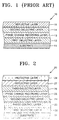
- FIG 1 is a vertical sectional view of a typical phase change optical disc.
- a conventional phase change optical disc has a multilayer structure in which a first dielectric layer 12, a phase change recording layer 13, which is formed of a phase change material whose optical characteristic varies with irradiation of a recording beam, a second dielectric layer 14 and reflective layer 15, are sequentially laminated on a transparent substrate 11, which is formed of, for example, acrylic acid resin or polycarbonate (PC).
- a transparent substrate 11 which is formed of, for example, acrylic acid resin or polycarbonate (PC).
- the first and second dielectric layers 12 and 14 are typically formed of ZnS-SiO 2 .
- the phase change recording layer 13 is formed of Ge 2 Sb 2 Te 5 .
- the reflective layer 15 is formed of aluminum (Al) or aluminum alloy.
- Information is recorded on or reproduced from this conventional phase change optical disc 10 having a multilayer structure. This is based on its characteristic that a part of the phase change recording layer 13, on which a laser beam is applied, becomes a crystalline or amorphous state depending on the power of the incident laser beam and the cooling speed, and thus the optical characteristic of the phase change recording layer 13 is changed. Information is recorded by generating a record mark by melting the phase change recording layer 13, which is initialized to a crystal phase by laser beam irradiation, using a recording pulse of high power and then rapidly cooling it into an amorphous state.
- the information of a record mark is reproduced as an electrical signal by a photodetector, which detects the difference between the reflectances.
- information is removed by removing a record mark by crystalizing the amorphous record mark using an erasing pulse of low power.
- the size of a record mark becomes smaller as the recording density increases.
- the size of a record mark becomes smaller, cross-talk occurs between adjacent marks during reproduction of a signal, thus deteriorating the characteristics of the reproduced signal.
- the resolving power for reproducing the signal becomes poor.
- the resolving power for reproducing the signal of a phase change optical disc depends on the wavelength ( ⁇ ) of a laser beam and numerical aperture (N.A.) of an object lens in an optical system.
- the characteristic of the reproduced signal is bad when the length of a record mark (or a pit) formed on an optical disc is smaller than the value of ⁇ /(2 N.A.), indicating a diffraction limit.
- the characteristic of the reproduced signal is good when the length of a record mark (or a pit) formed on an optical disc is greater than the value of ⁇ /(2 N.A.), indicating a diffraction limit. Accordingly, it is required to decrease the wavelength of a laser beam and to increase the numerical aperture of an objective lens for the purpose of recording information on a phase change optical disc at a high density.
- a phase change optical disc including at least one first dielectric layer thinly formed on a transparent substrate; a phase change recording layer which reversibly converts between a crystal phase and an amorphous phase by irradiation with a recording beam; a reflective layer; and a phase control layer disposed between the substrate and the reflective layer, the phase control layer having two areas where a phase difference occurs due to irradiation with a reproduction beam, thus altering the optical path of the reproduction beam, the two areas being defined in a laser spot.
- phase change optical disc on the transparent substrate are sequentially laminated the first dielectric layer, the phase control layer, on which the two areas where a phase difference occurs due to irradiation with the reproduction beam, thus altering the optical path of the reproduction beam, are defined in a laser spot, a second dielectric layer, the phase change recording layer, which reversibly converts between a crystal phase and an amorphous phase by irradiation with a recording beam, a third dielectric layer, the reflective layer, and a protective layer.
- the phase change optical disc may further comprise a fourth dielectric layer between the reflective layer and the protective layer.
- the phase control layer is formed of a phase change material which reversibly converts between a crystal phase and an amorphous phase or converts from a crystal phase of one structure to a crystal phase of another structure.
- the phase difference substantially has a minimum value of 0 degrees in one of the two areas defined on the phase control layer, and a maximum value of 180 degrees.
- the phase control layer is formed of a phase change material which reversibly converts between a crystal phase and an amorphous phase or converts from a crystal phase of one structure to a crystal phase of another structure.
- the phase control layer is preferably formed of a material selected among the GeSbTe family, InSbTe family, AgInSb family, Au and Ni.
- the phase change recording layer is formed of a material selected from the group consisting of the GeSbTe family, InSbTe family and the AgInSbTe family.
- each of the first, second and third dielectric layers is formed of a material selected from the group consisting of Al 2 O 3 , ZnS-SiO 2 , Si 3 N 4 , SiO 2 , MgF 2 , NaF 2 , LiF 2 , CaF 2 and AlF 2 .
- the reflective layer is formed of a material selected from the group consisting of Al, Al-Ti, Cu, Au and alloys of any of the above
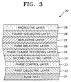
- a phase change optical disc 20 has a multilayer structure in which a first dielectric layer 22, a phase control layer 23, a second dielectric layer 24, a phase change recording layer 25, a third dielectric layer 26, a reflective layer 27 and a protective layer 29 are sequentially laminated on a transparent substrate 21, which is formed of, for example, a transparent acrylic acid resin material or a polycarbonate material.
- an optical disc 20' may further include a fourth dielectric layer 28 between the reflective layer 27 and the protective layer 29 in the multilayer structure shown in Figure 2.
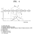
- the phase control layer 23 has the distribution of temperature shown in Figure 4 when a reproduction beam of high power is applied thereon. According to this distribution of temperature, the phase control layer 23 can be divided into a low temperature area and a high temperature area on the basis of a transition point TP. Since refractivity varies with the temperature, phase difference occurs. In other words, the high temperature area becomes a mask area (mark), and the low temperature area becomes an aperture area (space). In the mask area, the reflectance of a record mark is the same as that of the peripheral space, and the phase difference is 0 degrees, and thus the amount of reflected beam of the mask area is 0.
- the reflectance of a record mark is the same as that of the peripheral space, and the phase difference is 180 degrees, and thus the amount of reflected beam of the aperture area is maximum.
- phase difference occurs in two areas, and thus two areas, in which the optical path of the reproduction beam changes, are defined in a laser spot.
- the phase difference substantially has a minimum value of 0 degrees in one of the two areas and a maximum value of 180 degrees in the other area.
- the phase control layer 23 is formed of phase change material, such as a compound from the GeSbTe family, InSbTe family, AgInSbTe family, or Au or Ni, which reversibly converts between a crystal phase and an amorphous phase or converts from a crystal phase of one structure to a crystal phase of another structure by irradiation with a reproducing beam.
- phase change material such as a compound from the GeSbTe family, InSbTe family, AgInSbTe family, or Au or Ni, which reversibly converts between a crystal phase and an amorphous phase or converts from a crystal phase of one structure to a crystal phase of another structure by irradiation with a reproducing beam.
- the phase change recording layer 25 is formed of material, such as a compound from the GeSbTe family, InSbTe family or AgInSbTe family, which reversibly converts between a crystal phase and an amorphous phase by irradiation with a recording beam.
- the first through third dielectric layers 22, 24 and 26 are usually formed of a material having a low refractivity to correlatively control the light absorptances and reflectances of the crystalline and amorphous phases of the phase change recording layer 25.
- each of these layers 22, 24 and 26 may be formed of Al 2 O 3 , ZnS-SiO 2 , Si 3 N 4 , SiO 2 , MgF 2 , NaF 2 , LiF 2 , CaF 2 or AlF 2 .
- the reflective layer 27 is formed of metal of excellent quality, for example, Al, a compound from the Al-Ti family, Cu, Au or an alloy thereof.
- phase change optical disc having a multilayer structure as described above, information is recorded by generating a record mark by melting the phase change recording layer 25, which is initialized to a crystal phase by laser beam irradiation, using a recording pulse of high power and then cooling it into an amorphous state.
- the refractivity of the phase control layer 23 changes due to an increase in a temperature, which results from the irradiation with a reproduction beam, and thus the optical path of the reproduction beam changes.
- two local areas where the phase difference occurs are defined within the spot LS of the reproduction beam, as shown in Figure 4.
- a mask area M and an aperture area A are defined, and the phase difference of a reflected beam in each area makes it possible to reproduce the information of the record mark (or pit).
- the record mark P in the mask area M has the same reflectance as a peripheral space and has a phase difference of 0 degrees, thereby making a mask effect. Accordingly, it is ideal that the amount of reflected beam in the mask area M is 0, but there exists, actually, a little amount of reflected beam.
- the record mark P in the aperture area A has the same reflectance as a peripheral space and has a phase difference of 180 degrees, and thus the amount of the incident reproduction beam which is reflected becomes maximum. Accordingly, the signal of the reflected beam from the aperture area A is read, and thus only the information of the record mark P in the aperture area A is read, thereby implementing reproduction.
- This makes it possible to use the reflected beam from only the partial spot area (i.e., aperture area) of a reproduction beam so that the size of the effective spot of a reproduction beam can be reduced.
- phase difference with respect to a reflected beam occurs in the mask area and the aperture area within a laser spot on a phase control layer when a reproduction beam is incident, and the information of a record mark can be reproduced due to the phase difference. Therefore, the size of the effective spot of a reproduction beam can be reduced. Accordingly, the mixing of the signals between the adjacent marks or the adjacent tracks is decreased, and influence of cross-talk is also decreased, thereby realizing a high density optical disc and improving the resolution power of a reproduction signal.
Landscapes
- Physics & Mathematics (AREA)
- Nonlinear Science (AREA)
- Chemical & Material Sciences (AREA)
- Inorganic Chemistry (AREA)
- Optical Record Carriers And Manufacture Thereof (AREA)
- Optical Recording Or Reproduction (AREA)
- Thermal Transfer Or Thermal Recording In General (AREA)
Abstract
Description
Claims (9)
- A multilayered phase change optical disc including at least one first dielectric layer (22) thinly formed on a transparent substrate (21), a phase change recording layer (25) which reversibly converts between a crystal phase and an amorphous phase by irradiation with a recording beam, and a reflective layer (27),the phase change optical disc being characterized in that a phase control layer (23) is disposed between the substrate (21) and the reflective layer (27), the phase control layer having two areas where a phase difference occurs due to irradiation with a reproduction beam, thus altering the optical path of the reproduction beam, the two areas being defined in a laser spot.
- The phase change optical disc of claim 1, wherein on the transparent substrate (21) are sequentially laminated the first dielectric layer (22), the phase control layer (23), on which the two areas where a phase difference occurs due to irradiation with the reproduction beam, thus altering the optical path of the reproduction beam, are defined in a laser spot, a second dielectric layer (24), the phase change recording layer (25), which reversibly converts between a crystal phase and an amorphous phase by irradiation with a recording beam, a third dielectric layer (26), the reflective layer (27), and a protective layer (29).
- The phase change optical disc of claim 2, further comprising a fourth dielectric layer (28) between the reflective layer (27) and the protective layer (29).
- The phase change optical disc of any of claims 1, 2 and 3, wherein the phase control layer (23) is formed of a phase change material which reversibly converts between a crystal phase and an amorphous phase or converts from a crystal phase of one structure to a crystal phase of another structure.
- The phase change optical disc of any of claims 1, 2 and 3, wherein the phase difference substantially has a minimum value of 0 degrees in one of the two areas defined on the phase control layer, and a maximum value of 180 degrees.
- The phase change optical disc of any of the preceding claims, wherein the phase control layer (23) is formed of a material selected from the group consisting of the GeSbTe family, InSbTe family, AgInSb family, Au and Ni.
- The phase change optical disc of any of the preceding claims, wherein the phase change recording layer (25) is formed of a material selected from the group consisting of the GeSbTe family, InSbTe family and the AgInSbTe family.
- The phase change optical disc of any of the preceding claims, wherein each of the first, second and third dielectric layers (22; 24; 26) is formed of a material selected from the group consisting of Al2O3, ZnS-SiO2, Si3N4, SiO2, MgF2, NaF2, LiF2, CaF2 and AlF2.
- The phase change optical disc of any of the preceding claims, wherein the reflective layer (27) is formed of a material selected from the group consisting of Al, Al-Ti, Cu, Au and alloys of any of the above.
Applications Claiming Priority (2)
| Application Number | Priority Date | Filing Date | Title |
|---|---|---|---|
| KR9929278 | 1999-07-20 | ||
| KR1019990029278A KR100338756B1 (en) | 1999-07-20 | 1999-07-20 | Phase change optical medium |
Publications (2)
| Publication Number | Publication Date |
|---|---|
| EP1071087A2 true EP1071087A2 (en) | 2001-01-24 |
| EP1071087A3 EP1071087A3 (en) | 2006-02-08 |
Family
ID=19602919
Family Applications (1)
| Application Number | Title | Priority Date | Filing Date |
|---|---|---|---|
| EP00306118A Ceased EP1071087A3 (en) | 1999-07-20 | 2000-07-18 | Phase change optical disc |
Country Status (5)
| Country | Link |
|---|---|
| US (1) | US6835531B1 (en) |
| EP (1) | EP1071087A3 (en) |
| JP (1) | JP2001052376A (en) |
| KR (1) | KR100338756B1 (en) |
| CN (1) | CN1168081C (en) |
Cited By (1)
| Publication number | Priority date | Publication date | Assignee | Title |
|---|---|---|---|---|
| CN103268768A (en) * | 2013-04-03 | 2013-08-28 | 中国科学院上海光学精密机械研究所 | Disposable recording optical disc with surface plasma enhancement effect |
Families Citing this family (6)
| Publication number | Priority date | Publication date | Assignee | Title |
|---|---|---|---|---|
| JP2003296985A (en) * | 2002-03-28 | 2003-10-17 | Samsung Electronics Co Ltd | Recording method using reaction diffusion, recording medium using this method, and recording / reproducing apparatus using this recording medium |
| JP3940709B2 (en) * | 2003-07-01 | 2007-07-04 | 株式会社東芝 | Phase change optical recording medium |
| KR100856326B1 (en) * | 2006-07-19 | 2008-09-03 | 삼성전기주식회사 | Method of manufacturing a printed circuit board with a thin film capacitor having a dielectric thin film using a laser lift-off, and a printed circuit board with a thin film capacitor manufactured therefrom |
| JPWO2010106972A1 (en) * | 2009-03-18 | 2012-09-20 | 日本電気株式会社 | Optical information recording medium |
| CN101797824B (en) * | 2009-12-30 | 2012-10-10 | 中国科学院上海光学精密机械研究所 | Metal nanoparticle composite material and preparation method thereof |
| CN107195779A (en) * | 2017-05-27 | 2017-09-22 | 江苏理工学院 | A kind of GeSb/SiO2Multi-layer phase change film material, preparation method and application |
Family Cites Families (27)
| Publication number | Priority date | Publication date | Assignee | Title |
|---|---|---|---|---|
| NL8801327A (en) * | 1988-05-24 | 1989-12-18 | Philips Nv | METHOD OF OPTICAL SCANNING OF AN INFORMATION SHEET AND OPTICAL RECORD CARRIERS AND SCANNING DEVICES SUITABLE FOR APPLICATION OF THE METHOD. |
| US5255260A (en) * | 1989-07-28 | 1993-10-19 | Matsushita Electric Industrial Co., Ltd. | Optical recording apparatus employing stacked recording media with spiral grooves and floating optical heads |
| JP2661293B2 (en) * | 1989-11-15 | 1997-10-08 | 松下電器産業株式会社 | Optical information recording medium |
| JPH03275382A (en) * | 1990-03-27 | 1991-12-06 | Fuji Photo Film Co Ltd | Optical recording medium and recording regeneration method |
| DE69127398T2 (en) * | 1990-05-22 | 1998-01-02 | Canon Kk | Method and apparatus for recording and reproducing information in cells that use multiple interference |
| US5346740A (en) * | 1990-09-25 | 1994-09-13 | Matsushita Electric Industrial Co., Ltd. | Optical information recording medium |
| EP0525192B1 (en) * | 1991-02-15 | 1998-02-04 | Sony Corporation | Magnetooptical reproducing method and device |
| JP3297928B2 (en) | 1992-03-13 | 2002-07-02 | ソニー株式会社 | Read-only optical disc |
| JPH06251422A (en) | 1993-03-01 | 1994-09-09 | Sony Corp | Optical disk |
| JP3566743B2 (en) * | 1993-12-13 | 2004-09-15 | Tdk株式会社 | Optical recording medium |
| JPH10502202A (en) * | 1994-06-23 | 1998-02-24 | フィリップス エレクトロニクス ネムローゼ フェンノートシャップ | Optical information carrier |
| JP3506491B2 (en) * | 1994-06-23 | 2004-03-15 | Tdk株式会社 | Optical information media |
| JPH0863789A (en) | 1994-08-18 | 1996-03-08 | Sony Corp | optical disk |
| JPH097224A (en) * | 1995-06-26 | 1997-01-10 | Hitachi Ltd | Recording member, recording method and recording apparatus using the same |
| JPH0917028A (en) | 1995-06-30 | 1997-01-17 | Sony Corp | Optical information recording medium and information reproducing method thereof |
| JPH09134546A (en) * | 1995-09-07 | 1997-05-20 | Pioneer Electron Corp | Optical recording medium and method for reproducing its information signal |
| US5949751A (en) * | 1995-09-07 | 1999-09-07 | Pioneer Electronic Corporation | Optical recording medium and a method for reproducing information recorded from same |
| JPH0991700A (en) * | 1995-09-25 | 1997-04-04 | Sony Corp | Optical recording medium initialization method and initialization device used therefor |
| JPH09128807A (en) | 1995-10-31 | 1997-05-16 | Sony Corp | optical disk |
| JPH09128803A (en) * | 1995-10-31 | 1997-05-16 | Sony Corp | optical disk |
| TW414892B (en) * | 1996-05-28 | 2000-12-11 | Ibm | Optical data storage system with multiple rewriteable phase-change recording layers |
| JPH10269627A (en) * | 1997-03-21 | 1998-10-09 | Toshiba Corp | Optical recording medium and super-resolution reproduction method |
| JP3761287B2 (en) * | 1997-05-29 | 2006-03-29 | Tdk株式会社 | Optical recording medium and manufacturing method thereof |
| US6411591B1 (en) * | 1997-09-18 | 2002-06-25 | Hitachi, Ltd. | Optical recording medium and optical memory device |
| JP3130847B2 (en) * | 1997-10-30 | 2001-01-31 | 日本電気株式会社 | Optical information recording medium |
| TW473712B (en) * | 1998-05-12 | 2002-01-21 | Koninkl Philips Electronics Nv | Rewritable double layer optical information medium |
| JP4145446B2 (en) * | 1998-12-09 | 2008-09-03 | Tdk株式会社 | How to use optical recording media |
-
1999
- 1999-07-20 KR KR1019990029278A patent/KR100338756B1/en not_active Expired - Fee Related
-
2000
- 2000-07-18 EP EP00306118A patent/EP1071087A3/en not_active Ceased
- 2000-07-19 CN CNB001202804A patent/CN1168081C/en not_active Expired - Fee Related
- 2000-07-19 JP JP2000219739A patent/JP2001052376A/en active Pending
- 2000-07-20 US US09/620,469 patent/US6835531B1/en not_active Expired - Fee Related
Cited By (2)
| Publication number | Priority date | Publication date | Assignee | Title |
|---|---|---|---|---|
| CN103268768A (en) * | 2013-04-03 | 2013-08-28 | 中国科学院上海光学精密机械研究所 | Disposable recording optical disc with surface plasma enhancement effect |
| CN103268768B (en) * | 2013-04-03 | 2016-09-21 | 中国科学院上海光学精密机械研究所 | There is the once record CD of surface plasma enhancement effect |
Also Published As
| Publication number | Publication date |
|---|---|
| KR100338756B1 (en) | 2002-05-30 |
| JP2001052376A (en) | 2001-02-23 |
| KR20010010401A (en) | 2001-02-15 |
| US6835531B1 (en) | 2004-12-28 |
| CN1281217A (en) | 2001-01-24 |
| EP1071087A3 (en) | 2006-02-08 |
| CN1168081C (en) | 2004-09-22 |
Similar Documents
| Publication | Publication Date | Title |
|---|---|---|
| KR100312365B1 (en) | Informat10n recording medium and information recording and reproducing apparatus using the same | |
| KR100486324B1 (en) | Multivalue recording and reproducing method and phase change multivalue recording medium | |
| KR100746263B1 (en) | Optical information carriers with separate recording layers | |
| TW476065B (en) | Optical disk medium | |
| KR100770768B1 (en) | Optical record carrier and recording method using the optical record carrier | |
| US7442424B2 (en) | Information storage medium having super resolution structure and apparatus for recording to and/or reproducing from the same | |
| KR100731472B1 (en) | Optical record reproducing method and optical recording medium | |
| EP1071087A2 (en) | Phase change optical disc | |
| KR100678301B1 (en) | Optical record reproducing method and optical recording medium | |
| JP2003162844A (en) | Optical information recording medium | |
| US20070263527A1 (en) | Method and apparatus for recording/reproducing optical information | |
| JP3297928B2 (en) | Read-only optical disc | |
| KR100662671B1 (en) | Optical record carrier with germanium-antimony-tellurium recording layer | |
| EP1103963A1 (en) | Phase change optical disc | |
| US20040246868A1 (en) | Optical recording medium | |
| JP2002237098A (en) | Optical recording medium | |
| KR100694031B1 (en) | Phase change optical disk | |
| JP3430610B2 (en) | optical disk | |
| JP2003173573A (en) | Optical information recording medium and optical disk drive | |
| JP4152497B2 (en) | Optical recording medium | |
| JPH0917032A (en) | Optical information recording medium | |
| KR20010029133A (en) | Phase change optical disc | |
| JPH09134546A (en) | Optical recording medium and method for reproducing its information signal | |
| JP2000113505A (en) | Phase change optical disk | |
| JPH07254154A (en) | Optical disc signal reproducing method and optical disc used therefor |
Legal Events
| Date | Code | Title | Description |
|---|---|---|---|
| PUAI | Public reference made under article 153(3) epc to a published international application that has entered the european phase |
Free format text: ORIGINAL CODE: 0009012 |
|
| 17P | Request for examination filed |
Effective date: 20000727 |
|
| AK | Designated contracting states |
Kind code of ref document: A2 Designated state(s): AT BE CH CY DE DK ES FI FR GB GR IE IT LI LU MC NL PT SE |
|
| AX | Request for extension of the european patent |
Free format text: AL;LT;LV;MK;RO;SI |
|
| PUAL | Search report despatched |
Free format text: ORIGINAL CODE: 0009013 |
|
| AK | Designated contracting states |
Kind code of ref document: A3 Designated state(s): AT BE CH CY DE DK ES FI FR GB GR IE IT LI LU MC NL PT SE |
|
| AX | Request for extension of the european patent |
Extension state: AL LT LV MK RO SI |
|
| RIC1 | Information provided on ipc code assigned before grant |
Ipc: G11B 7/24 20060101ALI20051222BHEP Ipc: G11B 7/005 20060101AFI20051222BHEP |
|
| 17Q | First examination report despatched |
Effective date: 20060726 |
|
| AKX | Designation fees paid |
Designated state(s): DE FR GB NL |
|
| STAA | Information on the status of an ep patent application or granted ep patent |
Free format text: STATUS: THE APPLICATION HAS BEEN REFUSED |
|
| 18R | Application refused |
Effective date: 20080616 |