EP1070909A1 - Lighting device - Google Patents
Lighting device Download PDFInfo
- Publication number
- EP1070909A1 EP1070909A1 EP00902136A EP00902136A EP1070909A1 EP 1070909 A1 EP1070909 A1 EP 1070909A1 EP 00902136 A EP00902136 A EP 00902136A EP 00902136 A EP00902136 A EP 00902136A EP 1070909 A1 EP1070909 A1 EP 1070909A1
- Authority
- EP
- European Patent Office
- Prior art keywords
- lighting device
- composite element
- light
- infra
- leds
- Prior art date
- Legal status (The legal status is an assumption and is not a legal conclusion. Google has not performed a legal analysis and makes no representation as to the accuracy of the status listed.)
- Granted
Links
Images

Classifications
-
- F—MECHANICAL ENGINEERING; LIGHTING; HEATING; WEAPONS; BLASTING
- F21—LIGHTING
- F21V—FUNCTIONAL FEATURES OR DETAILS OF LIGHTING DEVICES OR SYSTEMS THEREOF; STRUCTURAL COMBINATIONS OF LIGHTING DEVICES WITH OTHER ARTICLES, NOT OTHERWISE PROVIDED FOR
- F21V29/00—Protecting lighting devices from thermal damage; Cooling or heating arrangements specially adapted for lighting devices or systems
- F21V29/50—Cooling arrangements
- F21V29/56—Cooling arrangements using liquid coolants
-
- F—MECHANICAL ENGINEERING; LIGHTING; HEATING; WEAPONS; BLASTING
- F21—LIGHTING
- F21V—FUNCTIONAL FEATURES OR DETAILS OF LIGHTING DEVICES OR SYSTEMS THEREOF; STRUCTURAL COMBINATIONS OF LIGHTING DEVICES WITH OTHER ARTICLES, NOT OTHERWISE PROVIDED FOR
- F21V29/00—Protecting lighting devices from thermal damage; Cooling or heating arrangements specially adapted for lighting devices or systems
- F21V29/85—Protecting lighting devices from thermal damage; Cooling or heating arrangements specially adapted for lighting devices or systems characterised by the material
-
- F—MECHANICAL ENGINEERING; LIGHTING; HEATING; WEAPONS; BLASTING
- F21—LIGHTING
- F21V—FUNCTIONAL FEATURES OR DETAILS OF LIGHTING DEVICES OR SYSTEMS THEREOF; STRUCTURAL COMBINATIONS OF LIGHTING DEVICES WITH OTHER ARTICLES, NOT OTHERWISE PROVIDED FOR
- F21V5/00—Refractors for light sources
- F21V5/04—Refractors for light sources of lens shape
-
- F—MECHANICAL ENGINEERING; LIGHTING; HEATING; WEAPONS; BLASTING
- F21—LIGHTING
- F21V—FUNCTIONAL FEATURES OR DETAILS OF LIGHTING DEVICES OR SYSTEMS THEREOF; STRUCTURAL COMBINATIONS OF LIGHTING DEVICES WITH OTHER ARTICLES, NOT OTHERWISE PROVIDED FOR
- F21V7/00—Reflectors for light sources
- F21V7/22—Reflectors for light sources characterised by materials, surface treatments or coatings, e.g. dichroic reflectors
- F21V7/28—Reflectors for light sources characterised by materials, surface treatments or coatings, e.g. dichroic reflectors characterised by coatings
-
- F—MECHANICAL ENGINEERING; LIGHTING; HEATING; WEAPONS; BLASTING
- F21—LIGHTING
- F21V—FUNCTIONAL FEATURES OR DETAILS OF LIGHTING DEVICES OR SYSTEMS THEREOF; STRUCTURAL COMBINATIONS OF LIGHTING DEVICES WITH OTHER ARTICLES, NOT OTHERWISE PROVIDED FOR
- F21V9/00—Elements for modifying spectral properties, polarisation or intensity of the light emitted, e.g. filters
- F21V9/04—Elements for modifying spectral properties, polarisation or intensity of the light emitted, e.g. filters for filtering out infrared radiation
-
- F—MECHANICAL ENGINEERING; LIGHTING; HEATING; WEAPONS; BLASTING
- F21—LIGHTING
- F21W—INDEXING SCHEME ASSOCIATED WITH SUBCLASSES F21K, F21L, F21S and F21V, RELATING TO USES OR APPLICATIONS OF LIGHTING DEVICES OR SYSTEMS
- F21W2131/00—Use or application of lighting devices or systems not provided for in codes F21W2102/00-F21W2121/00
- F21W2131/20—Lighting for medical use
- F21W2131/202—Lighting for medical use for dentistry
-
- F—MECHANICAL ENGINEERING; LIGHTING; HEATING; WEAPONS; BLASTING
- F21—LIGHTING
- F21W—INDEXING SCHEME ASSOCIATED WITH SUBCLASSES F21K, F21L, F21S and F21V, RELATING TO USES OR APPLICATIONS OF LIGHTING DEVICES OR SYSTEMS
- F21W2131/00—Use or application of lighting devices or systems not provided for in codes F21W2102/00-F21W2121/00
- F21W2131/20—Lighting for medical use
- F21W2131/205—Lighting for medical use for operating theatres
-
- F—MECHANICAL ENGINEERING; LIGHTING; HEATING; WEAPONS; BLASTING
- F21—LIGHTING
- F21Y—INDEXING SCHEME ASSOCIATED WITH SUBCLASSES F21K, F21L, F21S and F21V, RELATING TO THE FORM OR THE KIND OF THE LIGHT SOURCES OR OF THE COLOUR OF THE LIGHT EMITTED
- F21Y2115/00—Light-generating elements of semiconductor light sources
- F21Y2115/10—Light-emitting diodes [LED]
-
- Y—GENERAL TAGGING OF NEW TECHNOLOGICAL DEVELOPMENTS; GENERAL TAGGING OF CROSS-SECTIONAL TECHNOLOGIES SPANNING OVER SEVERAL SECTIONS OF THE IPC; TECHNICAL SUBJECTS COVERED BY FORMER USPC CROSS-REFERENCE ART COLLECTIONS [XRACs] AND DIGESTS
- Y10—TECHNICAL SUBJECTS COVERED BY FORMER USPC
- Y10S—TECHNICAL SUBJECTS COVERED BY FORMER USPC CROSS-REFERENCE ART COLLECTIONS [XRACs] AND DIGESTS
- Y10S362/00—Illumination
- Y10S362/80—Light emitting diode
Definitions
- the present invention relates to a lighting device, in particular a lighting device that may be applied to a shadowless lamp or a portable lighting unit useful in dental or surgical diagnosis.
- shadowless lamps are commonly used for casting appropriate light on and around a working site.
- halogen lamps have conventionally been used.
- the halogen lamps generate heat when electric current flows through the filament, such that the surface temperature of the lamps rises to as high as 200 to 300°C, thereby having problems in safety.
- Such calefacient light also discomforts the patients and doctors.
- the halogen lamps are not resistant to vibration, short in service life, and expensive.
- a lighting device comprising a composite element having a plurality of light emitting diodes arranged in rows and columns.
- the composite element is in the form of a plate composed of a plurality of light emitting diodes (referred to as "LEDs" hereinbelow) arranged in rows and columns.
- the shape of the plate is not particularly limited, and may be circular, oval, or polygonal such as rectangular shape.
- the composite element compared to the halogen lamps, provides a higher light transforming rate and thus a remarkably less heat release value, thus being safe.
- the composite element is free of filaments, which structure results in high impact-resistance and long service life, and realizes light emission at low voltage and current, thus being advantageous in cost.
- the lighting device of the present invention may further have heat removing means for removing heat generated by the composite element, and light controlling means for controlling the light paths of the LEDs.
- the heat removing means removes the uncomfortable feeling of heat given by the light rays emitted by the LEDs.
- Examples of the heat removing means for this application include a layer having an infra-red cut-out layer for cutting out at least a portion of the infra-red rays of the light emitted by the LEDs, and a liquid cooling agent for cooling the surface of the LEDs of the composite element.
- the layer having an infra-red cut-out layer may preferably be a radiator plate that transmits only the infra-red rays, or a special coating that absorbs the infra-red rays.
- the cooling agent may preferably be a silicon oil.
- the lighting device of the present invention may further be provided with a reflector that reflects the light rays emitted by the LEDs of the composite element in the direction of the irradiation. With such a reflector, the present lighting device can be used as a shadowless lamp.
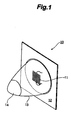
- Fig. 1 is a schematic explanatory view of a lighting device 10 according to the present invention.
- the lighting device 10 includes a composite element 11 having a plurality of LEDs as a light source, a radiator plate 12 carrying the composite element 11 in the center of its surface, a transparent casing 13 generally in the form of a conical cup projecting from the front surface of the radiator plate 12 and encasing the composite element 11 therein, and an aspheric lens 14 provided in the tip portion of the transparent casing 13 and functioning as light controlling means.
- the transparent casing 13 is sealingly filled with about 40cc of a silicon oil as a cooling agent, and the transparent casing 13 and the radiator plate 12 are sealed to each other in a water-tight manner.
- the composite element 11 has forty LEDs arranged in eight rows of five LEDs each.
- the electric power consumption of the element 11 is 3.2 W (3.2 V ⁇ 1 A).
- the radiator plate 12 is designed so as to transmit rearward through the plate 12 the infra-red rays of the light emitted by the LEDs of the composite element 11 and to reflect the visible light rays forward.
- the aspheric lens 14 is capable of controlling the light paths as desired.
- the heat release value of the composite element 11, when the LEDs are on, is such that one can touch the element 11 with its hands to feel hot, and is remarkably lower than that of the halogen lamps.
- the light rays emitted by the composite element 11 give uncomfortable feeling of heat. Such feeling of heat is, however, mitigated by placing the composite element 11 in contact with the silicon oil acting as a cooling agent sealingly contained in the transparent casing 13, to lower the surface temperature of the composite element 11 to about 40 °C.
- the uncomfortable feeling of heat is further removed effectively by the radiator plate 12 dissipating the infra-red rays emitted by the composite element.
- the radiator plate 12 and the silicon oil constitute the heat removing means.
- the lighting device 10 may be mounted on a suitable stand or arm.
- the lighting device 10 may be mounted for use on an arm 21 attached to a portable case 20 for accommodating medical instruments (22a-22c) as shown in Fig. 2.
- the radiator plate 12 is replaced with a reflector (not shown).
- the reflector is composed of a combination of special parabolic surfaces and corrugated curves designed to give light condensing and shadowless effects, and reflects more than 90 % of the visible light rays.
- the reflector may be provided on its rear surface with a special coating capable of absorbing the infra-red rays, to make the reflector function also as a radiator plate.
- the composite element including a plurality of LEDs as a light source provides the lighting device of the present invention with remarkably improved safety, durability, and economic efficiency, compared to the conventional lighting devices employing halogen lamps as a light source.
Landscapes
- Engineering & Computer Science (AREA)
- General Engineering & Computer Science (AREA)
- Physics & Mathematics (AREA)
- Spectroscopy & Molecular Physics (AREA)
- Arrangement Of Elements, Cooling, Sealing, Or The Like Of Lighting Devices (AREA)
- Led Device Packages (AREA)
- Led Devices (AREA)
- Non-Portable Lighting Devices Or Systems Thereof (AREA)
- Circuit Arrangement For Electric Light Sources In General (AREA)
- Vehicle Body Suspensions (AREA)
- Polarising Elements (AREA)
- Seal Device For Vehicle (AREA)
Abstract
Description
Claims (5)
- A lighting device comprising as a light source a composite element having a plurality of light emitting diodes arranged in rows and columns.
- The lighting device of claim 1 further comprising:heat removing means for removing heat generated by said composite element, andlight controlling means for controlling a path of light emitted by said composite element.
- The lighting device of claim 2 wherein said heat removing means comprises at least one of a layer having an infra-red cut-out layer for cutting out at least a portion of infra-red rays in light emitted by said composite element, and a liquid cooling agent for contacting and cooling a surface of said composite element.
- The lighting device of claim 3 wherein said liquid cooling agent is a silicon oil.
- The lighting device of claim 1 further comprising a reflector for reflecting light rays emitted by said composite element back in a direction of irradiation.
Applications Claiming Priority (3)
| Application Number | Priority Date | Filing Date | Title |
|---|---|---|---|
| JP3126199 | 1999-02-09 | ||
| JP03126199A JP3149402B2 (en) | 1999-02-09 | 1999-02-09 | Medical lighting equipment |
| PCT/JP2000/000670 WO2000047930A1 (en) | 1999-02-09 | 2000-02-08 | Lighting device |
Publications (3)
| Publication Number | Publication Date |
|---|---|
| EP1070909A1 true EP1070909A1 (en) | 2001-01-24 |
| EP1070909A4 EP1070909A4 (en) | 2007-05-23 |
| EP1070909B1 EP1070909B1 (en) | 2009-01-28 |
Family
ID=12326418
Family Applications (1)
| Application Number | Title | Priority Date | Filing Date |
|---|---|---|---|
| EP00902136A Expired - Lifetime EP1070909B1 (en) | 1999-02-09 | 2000-02-08 | Lighting device |
Country Status (6)
| Country | Link |
|---|---|
| US (1) | US6523979B1 (en) |
| EP (1) | EP1070909B1 (en) |
| JP (1) | JP3149402B2 (en) |
| AT (1) | ATE422033T1 (en) |
| DE (1) | DE60041474D1 (en) |
| WO (1) | WO2000047930A1 (en) |
Cited By (1)
| Publication number | Priority date | Publication date | Assignee | Title |
|---|---|---|---|---|
| US7722211B2 (en) | 2004-08-06 | 2010-05-25 | Koninklijke Philips Electronics N.V. | Light engine |
Families Citing this family (10)
| Publication number | Priority date | Publication date | Assignee | Title |
|---|---|---|---|---|
| US6709128B2 (en) * | 2001-03-26 | 2004-03-23 | Ocumed, Inc. | Curing system |
| JP2004309635A (en) * | 2003-04-03 | 2004-11-04 | Samsung Electronics Co Ltd | Optical scanning device |
| JP4735794B2 (en) * | 2003-06-30 | 2011-07-27 | 信越半導体株式会社 | Light emitting module |
| JP4451711B2 (en) * | 2004-05-17 | 2010-04-14 | 日油技研工業株式会社 | Underwater lighting equipment |
| USD510151S1 (en) * | 2004-06-24 | 2005-09-27 | Hamid Rashidi | Square frame trim ring |
| US8016470B2 (en) | 2007-10-05 | 2011-09-13 | Dental Equipment, Llc | LED-based dental exam lamp with variable chromaticity |
| US8459852B2 (en) | 2007-10-05 | 2013-06-11 | Dental Equipment, Llc | LED-based dental exam lamp |
| JP4609374B2 (en) * | 2006-05-01 | 2011-01-12 | パナソニック電工株式会社 | Luminescent panel lighting fixture |
| JP5148126B2 (en) * | 2007-02-09 | 2013-02-20 | スタンレー電気株式会社 | Color conversion light emitting device and manufacturing method thereof |
| WO2013138690A1 (en) | 2012-03-16 | 2013-09-19 | Forelight, Llc | Methods and materials for cultivation and/or propagation of a photosynthetic organism |
Family Cites Families (15)
| Publication number | Priority date | Publication date | Assignee | Title |
|---|---|---|---|---|
| US3596125A (en) * | 1969-06-09 | 1971-07-27 | Wayne A Seigel | Liquid cooled radiation source with filter |
| JPS558909U (en) * | 1978-07-03 | 1980-01-21 | ||
| US4254455A (en) * | 1979-12-21 | 1981-03-03 | Pelton & Crane Company | Reflector for dental, medical or the like lighting device |
| ATE47624T1 (en) * | 1984-11-15 | 1989-11-15 | Japan Traffic Manage Tech Ass | SIGNAL LIGHT UNIT WITH HEAT DISSIPATION. |
| JP2681133B2 (en) | 1989-08-17 | 1997-11-26 | 東京エレクトロン株式会社 | Processing method |
| JPH0777081B2 (en) * | 1990-03-26 | 1995-08-16 | 株式会社ゼニライトブイ | Lantern and lantern lens |
| KR100449129B1 (en) * | 1995-10-25 | 2005-01-24 | 인스트루먼츠 인코포레이티드 텍사스 | Investigation system |
| US5707139A (en) * | 1995-11-01 | 1998-01-13 | Hewlett-Packard Company | Vertical cavity surface emitting laser arrays for illumination |
| US5890794A (en) * | 1996-04-03 | 1999-04-06 | Abtahi; Homayoon | Lighting units |
| JPH10144964A (en) * | 1996-11-07 | 1998-05-29 | Metro Denki Kogyo Kk | Led lamp |
| JP3366199B2 (en) * | 1996-12-10 | 2003-01-14 | 株式会社長田中央研究所 | Dental lighting and monitoring equipment |
| JP3596208B2 (en) * | 1997-01-28 | 2004-12-02 | 松下電工株式会社 | Automatic lighting device |
| JPH10233534A (en) * | 1997-02-21 | 1998-09-02 | Nichia Chem Ind Ltd | LED display and display device using the same |
| US6200134B1 (en) * | 1998-01-20 | 2001-03-13 | Kerr Corporation | Apparatus and method for curing materials with radiation |
| JP3077674B2 (en) * | 1998-06-29 | 2000-08-14 | 日本電気株式会社 | Moving object approach prediction method |
-
1999
- 1999-02-09 JP JP03126199A patent/JP3149402B2/en not_active Expired - Lifetime
-
2000
- 2000-02-08 EP EP00902136A patent/EP1070909B1/en not_active Expired - Lifetime
- 2000-02-08 AT AT00902136T patent/ATE422033T1/en active
- 2000-02-08 DE DE60041474T patent/DE60041474D1/en not_active Expired - Lifetime
- 2000-02-08 WO PCT/JP2000/000670 patent/WO2000047930A1/en not_active Ceased
- 2000-10-05 US US09/679,920 patent/US6523979B1/en not_active Expired - Lifetime
Cited By (1)
| Publication number | Priority date | Publication date | Assignee | Title |
|---|---|---|---|---|
| US7722211B2 (en) | 2004-08-06 | 2010-05-25 | Koninklijke Philips Electronics N.V. | Light engine |
Also Published As
| Publication number | Publication date |
|---|---|
| JP3149402B2 (en) | 2001-03-26 |
| WO2000047930A1 (en) | 2000-08-17 |
| DE60041474D1 (en) | 2009-03-19 |
| EP1070909B1 (en) | 2009-01-28 |
| JP2000231802A (en) | 2000-08-22 |
| ATE422033T1 (en) | 2009-02-15 |
| EP1070909A4 (en) | 2007-05-23 |
| US6523979B1 (en) | 2003-02-25 |
Similar Documents
| Publication | Publication Date | Title |
|---|---|---|
| EP1070909B1 (en) | Lighting device | |
| US7207694B1 (en) | Light emitting diode operating and examination light system | |
| US20200154990A1 (en) | Dental light using leds | |
| JP5627795B2 (en) | Wearable headlight device and related methods | |
| EP1304977B2 (en) | Apparatus for curing materials with light radiation | |
| JP4056930B2 (en) | Medical light irradiation device | |
| US20050117327A1 (en) | Surgical headlight | |
| EP2042123A2 (en) | Curing light instrument | |
| JPH07147103A (en) | Light emitting equipment | |
| US7815342B2 (en) | Surgical headlamp | |
| CN1550223A (en) | Light irradiation device for medical use | |
| CN102812292A (en) | Improved LED type dental examination light | |
| WO2006033998A1 (en) | Thermal management system for solid state automotive lighting | |
| US7490949B2 (en) | Surgical headlamp | |
| US20070097703A1 (en) | Integral solid-state luminaire with dual light paths and coaxial optics | |
| US7425077B2 (en) | LED-powered dental operatory light | |
| JP2009050572A (en) | Antifog mirror apparatus | |
| EP1418837A2 (en) | A new light source for diagnostic instruments | |
| US20080144306A1 (en) | Surgical headlamp | |
| WO2006080918A1 (en) | Surgical headlight | |
| JP3084178U (en) | Surgical light | |
| CN207804219U (en) | LED cold light source for medical endoscope device and module | |
| WO2012018277A1 (en) | Lighting device | |
| CN202776235U (en) | LED medical cold light source | |
| JPWO2018193540A1 (en) | Head-mounted lighting device |
Legal Events
| Date | Code | Title | Description |
|---|---|---|---|
| PUAI | Public reference made under article 153(3) epc to a published international application that has entered the european phase |
Free format text: ORIGINAL CODE: 0009012 |
|
| 17P | Request for examination filed |
Effective date: 20001006 |
|
| AK | Designated contracting states |
Kind code of ref document: A1 Designated state(s): AT BE CH CY DE DK ES FI FR GB GR IE IT LI LU MC NL PT SE |
|
| RBV | Designated contracting states (corrected) |
Designated state(s): AT CH DE FR GB IT LI |
|
| A4 | Supplementary search report drawn up and despatched |
Effective date: 20070420 |
|
| 17Q | First examination report despatched |
Effective date: 20070907 |
|
| GRAP | Despatch of communication of intention to grant a patent |
Free format text: ORIGINAL CODE: EPIDOSNIGR1 |
|
| GRAS | Grant fee paid |
Free format text: ORIGINAL CODE: EPIDOSNIGR3 |
|
| GRAA | (expected) grant |
Free format text: ORIGINAL CODE: 0009210 |
|
| RAP1 | Party data changed (applicant data changed or rights of an application transferred) |
Owner name: NAKANISHI INC. |
|
| AK | Designated contracting states |
Kind code of ref document: B1 Designated state(s): AT CH DE FR GB IT LI |
|
| REG | Reference to a national code |
Ref country code: GB Ref legal event code: FG4D |
|
| REG | Reference to a national code |
Ref country code: CH Ref legal event code: NV Representative=s name: KATZAROV S.A. Ref country code: CH Ref legal event code: EP |
|
| REF | Corresponds to: |
Ref document number: 60041474 Country of ref document: DE Date of ref document: 20090319 Kind code of ref document: P |
|
| PLBE | No opposition filed within time limit |
Free format text: ORIGINAL CODE: 0009261 |
|
| STAA | Information on the status of an ep patent application or granted ep patent |
Free format text: STATUS: NO OPPOSITION FILED WITHIN TIME LIMIT |
|
| 26N | No opposition filed |
Effective date: 20091029 |
|
| PGFP | Annual fee paid to national office [announced via postgrant information from national office to epo] |
Ref country code: FR Payment date: 20140212 Year of fee payment: 15 Ref country code: AT Payment date: 20140227 Year of fee payment: 15 Ref country code: IT Payment date: 20140221 Year of fee payment: 15 |
|
| PGFP | Annual fee paid to national office [announced via postgrant information from national office to epo] |
Ref country code: GB Payment date: 20140310 Year of fee payment: 15 |
|
| PGFP | Annual fee paid to national office [announced via postgrant information from national office to epo] |
Ref country code: DE Payment date: 20140428 Year of fee payment: 15 Ref country code: CH Payment date: 20140513 Year of fee payment: 15 |
|
| REG | Reference to a national code |
Ref country code: DE Ref legal event code: R119 Ref document number: 60041474 Country of ref document: DE |
|
| REG | Reference to a national code |
Ref country code: CH Ref legal event code: PL |
|
| REG | Reference to a national code |
Ref country code: AT Ref legal event code: MM01 Ref document number: 422033 Country of ref document: AT Kind code of ref document: T Effective date: 20150208 |
|
| GBPC | Gb: european patent ceased through non-payment of renewal fee |
Effective date: 20150208 |
|
| PG25 | Lapsed in a contracting state [announced via postgrant information from national office to epo] |
Ref country code: CH Free format text: LAPSE BECAUSE OF NON-PAYMENT OF DUE FEES Effective date: 20150228 Ref country code: LI Free format text: LAPSE BECAUSE OF NON-PAYMENT OF DUE FEES Effective date: 20150228 |
|
| REG | Reference to a national code |
Ref country code: FR Ref legal event code: ST Effective date: 20151030 |
|
| PG25 | Lapsed in a contracting state [announced via postgrant information from national office to epo] |
Ref country code: AT Free format text: LAPSE BECAUSE OF NON-PAYMENT OF DUE FEES Effective date: 20150208 |
|
| PG25 | Lapsed in a contracting state [announced via postgrant information from national office to epo] |
Ref country code: IT Free format text: LAPSE BECAUSE OF NON-PAYMENT OF DUE FEES Effective date: 20150208 |
|
| PG25 | Lapsed in a contracting state [announced via postgrant information from national office to epo] |
Ref country code: GB Free format text: LAPSE BECAUSE OF NON-PAYMENT OF DUE FEES Effective date: 20150208 Ref country code: DE Free format text: LAPSE BECAUSE OF NON-PAYMENT OF DUE FEES Effective date: 20150901 |
|
| PG25 | Lapsed in a contracting state [announced via postgrant information from national office to epo] |
Ref country code: FR Free format text: LAPSE BECAUSE OF NON-PAYMENT OF DUE FEES Effective date: 20150302 |