EP1070861A2 - Coated fastener inserts and method of producing the same - Google Patents
Coated fastener inserts and method of producing the same Download PDFInfo
- Publication number
- EP1070861A2 EP1070861A2 EP00306143A EP00306143A EP1070861A2 EP 1070861 A2 EP1070861 A2 EP 1070861A2 EP 00306143 A EP00306143 A EP 00306143A EP 00306143 A EP00306143 A EP 00306143A EP 1070861 A2 EP1070861 A2 EP 1070861A2
- Authority
- EP
- European Patent Office
- Prior art keywords
- fastener
- coating
- insert
- coated
- fastener insert
- Prior art date
- Legal status (The legal status is an assumption and is not a legal conclusion. Google has not performed a legal analysis and makes no representation as to the accuracy of the status listed.)
- Granted
Links
- 238000000034 method Methods 0.000 title claims abstract description 37
- 239000011248 coating agent Substances 0.000 claims abstract description 31
- 238000000576 coating method Methods 0.000 claims abstract description 31
- 239000000203 mixture Substances 0.000 claims abstract description 15
- 229920002313 fluoropolymer Polymers 0.000 claims abstract description 14
- 239000004811 fluoropolymer Substances 0.000 claims abstract description 14
- 230000007797 corrosion Effects 0.000 claims abstract description 13
- 238000005260 corrosion Methods 0.000 claims abstract description 13
- 230000000712 assembly Effects 0.000 claims abstract description 8
- 238000000429 assembly Methods 0.000 claims abstract description 8
- 238000005507 spraying Methods 0.000 claims description 3
- 239000011347 resin Substances 0.000 abstract description 3
- 229920005989 resin Polymers 0.000 abstract description 3
- 229910052751 metal Inorganic materials 0.000 description 5
- 239000002184 metal Substances 0.000 description 5
- NDKWCCLKSWNDBG-UHFFFAOYSA-N zinc;dioxido(dioxo)chromium Chemical compound [Zn+2].[O-][Cr]([O-])(=O)=O NDKWCCLKSWNDBG-UHFFFAOYSA-N 0.000 description 5
- 238000009434 installation Methods 0.000 description 4
- 239000000758 substrate Substances 0.000 description 4
- ZWEHNKRNPOVVGH-UHFFFAOYSA-N 2-Butanone Chemical compound CCC(C)=O ZWEHNKRNPOVVGH-UHFFFAOYSA-N 0.000 description 3
- 239000000356 contaminant Substances 0.000 description 3
- 150000002739 metals Chemical class 0.000 description 3
- 239000002904 solvent Substances 0.000 description 3
- 239000007921 spray Substances 0.000 description 3
- 239000010935 stainless steel Substances 0.000 description 3
- 229910001220 stainless steel Inorganic materials 0.000 description 3
- 229920001221 xylan Polymers 0.000 description 3
- 150000004823 xylans Chemical class 0.000 description 3
- 238000004140 cleaning Methods 0.000 description 2
- 238000007796 conventional method Methods 0.000 description 2
- -1 i.e. Inorganic materials 0.000 description 2
- 229910052749 magnesium Inorganic materials 0.000 description 2
- 239000011777 magnesium Substances 0.000 description 2
- 239000000463 material Substances 0.000 description 2
- 239000010963 304 stainless steel Substances 0.000 description 1
- OYPRJOBELJOOCE-UHFFFAOYSA-N Calcium Chemical compound [Ca] OYPRJOBELJOOCE-UHFFFAOYSA-N 0.000 description 1
- FYYHWMGAXLPEAU-UHFFFAOYSA-N Magnesium Chemical compound [Mg] FYYHWMGAXLPEAU-UHFFFAOYSA-N 0.000 description 1
- 229910000589 SAE 304 stainless steel Inorganic materials 0.000 description 1
- 238000003916 acid precipitation Methods 0.000 description 1
- 239000000956 alloy Substances 0.000 description 1
- 229910045601 alloy Inorganic materials 0.000 description 1
- 229910052782 aluminium Inorganic materials 0.000 description 1
- XAGFODPZIPBFFR-UHFFFAOYSA-N aluminium Chemical compound [Al] XAGFODPZIPBFFR-UHFFFAOYSA-N 0.000 description 1
- 238000004873 anchoring Methods 0.000 description 1
- 238000005422 blasting Methods 0.000 description 1
- 229910052791 calcium Inorganic materials 0.000 description 1
- 239000011575 calcium Substances 0.000 description 1
- 239000003518 caustics Substances 0.000 description 1
- 239000008199 coating composition Substances 0.000 description 1
- 230000007547 defect Effects 0.000 description 1
- 238000005238 degreasing Methods 0.000 description 1
- 239000003599 detergent Substances 0.000 description 1
- 238000003618 dip coating Methods 0.000 description 1
- 238000009826 distribution Methods 0.000 description 1
- 239000003792 electrolyte Substances 0.000 description 1
- 238000006056 electrooxidation reaction Methods 0.000 description 1
- 230000007613 environmental effect Effects 0.000 description 1
- 239000004446 fluoropolymer coating Substances 0.000 description 1
- 239000004519 grease Substances 0.000 description 1
- 230000007246 mechanism Effects 0.000 description 1
- 230000004048 modification Effects 0.000 description 1
- 238000012986 modification Methods 0.000 description 1
- 239000003921 oil Substances 0.000 description 1
- 239000003208 petroleum Substances 0.000 description 1
- 230000002265 prevention Effects 0.000 description 1
- 238000003908 quality control method Methods 0.000 description 1
- 238000005488 sandblasting Methods 0.000 description 1
- 238000009987 spinning Methods 0.000 description 1
- 230000003068 static effect Effects 0.000 description 1
- 239000000126 substance Substances 0.000 description 1
- 238000011179 visual inspection Methods 0.000 description 1
Images

Classifications
-
- B—PERFORMING OPERATIONS; TRANSPORTING
- B05—SPRAYING OR ATOMISING IN GENERAL; APPLYING FLUENT MATERIALS TO SURFACES, IN GENERAL
- B05D—PROCESSES FOR APPLYING FLUENT MATERIALS TO SURFACES, IN GENERAL
- B05D5/00—Processes for applying liquids or other fluent materials to surfaces to obtain special surface effects, finishes or structures
- B05D5/08—Processes for applying liquids or other fluent materials to surfaces to obtain special surface effects, finishes or structures to obtain an anti-friction or anti-adhesive surface
- B05D5/083—Processes for applying liquids or other fluent materials to surfaces to obtain special surface effects, finishes or structures to obtain an anti-friction or anti-adhesive surface involving the use of fluoropolymers
-
- F—MECHANICAL ENGINEERING; LIGHTING; HEATING; WEAPONS; BLASTING
- F16—ENGINEERING ELEMENTS AND UNITS; GENERAL MEASURES FOR PRODUCING AND MAINTAINING EFFECTIVE FUNCTIONING OF MACHINES OR INSTALLATIONS; THERMAL INSULATION IN GENERAL
- F16B—DEVICES FOR FASTENING OR SECURING CONSTRUCTIONAL ELEMENTS OR MACHINE PARTS TOGETHER, e.g. NAILS, BOLTS, CIRCLIPS, CLAMPS, CLIPS OR WEDGES; JOINTS OR JOINTING
- F16B37/00—Nuts or like thread-engaging members
- F16B37/12—Nuts or like thread-engaging members with thread-engaging surfaces formed by inserted coil-springs, discs, or the like; Independent pieces of wound wire used as nuts; Threaded inserts for holes
-
- F—MECHANICAL ENGINEERING; LIGHTING; HEATING; WEAPONS; BLASTING
- F16—ENGINEERING ELEMENTS AND UNITS; GENERAL MEASURES FOR PRODUCING AND MAINTAINING EFFECTIVE FUNCTIONING OF MACHINES OR INSTALLATIONS; THERMAL INSULATION IN GENERAL
- F16B—DEVICES FOR FASTENING OR SECURING CONSTRUCTIONAL ELEMENTS OR MACHINE PARTS TOGETHER, e.g. NAILS, BOLTS, CIRCLIPS, CLAMPS, CLIPS OR WEDGES; JOINTS OR JOINTING
- F16B33/00—Features common to bolt and nut
- F16B33/004—Sealing; Insulation
-
- Y—GENERAL TAGGING OF NEW TECHNOLOGICAL DEVELOPMENTS; GENERAL TAGGING OF CROSS-SECTIONAL TECHNOLOGIES SPANNING OVER SEVERAL SECTIONS OF THE IPC; TECHNICAL SUBJECTS COVERED BY FORMER USPC CROSS-REFERENCE ART COLLECTIONS [XRACs] AND DIGESTS
- Y10—TECHNICAL SUBJECTS COVERED BY FORMER USPC
- Y10S—TECHNICAL SUBJECTS COVERED BY FORMER USPC CROSS-REFERENCE ART COLLECTIONS [XRACs] AND DIGESTS
- Y10S411/00—Expanded, threaded, driven, headed, tool-deformed, or locked-threaded fastener
- Y10S411/90—Fastener or fastener element composed of plural different materials
- Y10S411/901—Core and exterior of different materials
- Y10S411/902—Metal core
- Y10S411/903—Resinous exterior
Definitions
- the present invention relates to coated fastener inserts and a method for coating such fastener inserts and, more particularly, to coating fastener inserts to prevent the galvanic corrosion in fastener assemblies.
- Fastener assemblies come in a variety of shapes, sizes, designs and materials. Many fastener assemblies include not only a fastener such as a bolt, pin or screw, but also will include a fastener insert to be positioned within a tapped hole.
- tapped threads are strengthened due to the inherent flexibility of helically coiled wire inserts since the insert provides a more balanced distribution of dynamic and static loads throughout the length of thread engagement. This is especially important when the substrate including tapped holes is formed from a relatively soft metal, i.e., aluminum and magnesium. The inherent flexibility also compensates for variation in lead and angle error.
- Helically coiled wire inserts allow for the use of smaller bosses, flanges and fasteners than other inserts, thus presenting a cost savings, particularly for high volume applications.
- helically coiled wire inserts are generally useful as anchoring mechanisms for threaded fasteners in order to be used in high strength applications, such inserts must be formed from high strength metals such as 302/304 stainless steel.
- high strength metals such as 302/304 stainless steel.
- the use of stainless steel inserts in association with substrates or fasteners formed from other alloys leads to certain perceived problems such as the possibility of galvanic corrosion occurring over time.
- galvanic corrosion it is meant the electrochemical corrosion resulting from the current caused in a galvanic cell between two dissimilar metals in an electrolyte because of the difference in potential (emf) of the two metals.
- Stainless steel fastener inserts have been coated with zinc chromate in an effort to prevent galvanic corrosion.
- application of the zinc chromate requires strict quantitative controls and is considered labor intensive.
- the application of too much zinc chromate can restrict movement.
- the installation tools would require frequent cleaning to prevent build up of the zinc chromate on mandrels of the tool which is undesirable.
- the application of too little zinc chromate leads to certain other problems such as inadequate corrosion protection, for example.
- the present invention relates to a method for preventing galvanic corrosion in fastener assemblies employing a metallic fastener insert and a fastener for use in a tapped hole, said method comprising the steps of:
- the fastener insert is degreased prior to application of the fluoropolymer composition.
- the fastener insert surface to be coated may be abraded using a conventional technique such as grit blasting to enhance the coating's adhesion, wear resistance and overall durability. If the coated fastener insert is likely to be used in the presence of chemicals or corrosive agents, a primer composition may be employed after degreasing but prior to coating, as will be described in greater detail below.
- the present invention also relates to a coated metallic fastener insert for securing a fastener within a tapped hole, said insert comprising:
- the present invention further relates to a method of producing a fastener insert which is resistant to galvanic corrosion, said method comprising the steps of:
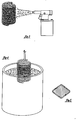
- a fastener assembly 10 for use in association with a substrate 12 having one or more tapped holes 14 including inwardly projecting threads 16.
- the fastener assembly 10 includes a fastener 20 and fastener insert 22 insertable within the tapped hole 14.
- the fastener 20 generally includes a head 24 and a shank 26 having radially outwardly projecting threads 28.
- the fastener insert 22 may be of any form capable of retaining the fastener within a tapped hole but preferably is in the form of a helically wound wire 30 including a body 32 having a plurality of convolutions 34 disposed between first and second ends, 36 and 38, respectively. At least one of the ends may be provided with a driving tang or notch for tangless embodiments for assistance in the installation or removal process.
- the fastener inserts 22 are larger in diameter, before installation than the tapped holes 14 such that upon installation they become firmly secured within the tapped holes, as shown most clearly in Fig. 2.
- the coils provide permanent convolution 60° internal screw threads which accommodate virtually any standard threaded bolt or screw.
- the insert Prior to inserting the fastener insert 22 within the tapped hole 14, the insert is coated with a resin bonded fluoropolymer composition such as XYLAN® 5251, available from Whitford Corporation of Westchester, Pennsylvania or E/M® 6219, which is available from Engineered Coating Solutions, Inc. of Peachtree City, Georgia, by way of non-limiting example.
- a resin bonded fluoropolymer composition such as XYLAN® 5251, available from Whitford Corporation of Westchester, Pennsylvania or E/M® 6219, which is available from Engineered Coating Solutions, Inc. of Peachtree City, Georgia, by way of non-limiting example.
- the composition be thoroughly agitated such that the fluoropolymer is adequately dispersed in solution.
- the fluoropolymer composition may be applied via dip spin or air spray techniques.
- the fluoropolymer composition may also serve to reduce galling. It is preferred that the dry film thickness be in the range of between 0.03 to about 0.5 mils. As such, it is preferred that under dip spin applications that at least two coats are applied to obtain the preferred thickness. Using conventional spray application techniques, a single coat of between about 0.6 to 1.0 mils. is possible.
- a preferred viscosity is generally in the range of between about 20 - 30 seconds at 25°C.
- the fastener inserts be free of contaminants such as oil, grease, metal shavings, etc., since contaminants may cause poor adhesion of the coating to the fastener insert or defects in the dry coating composition.
- the fastener inserts be cleaned, i.e., degreased prior to coating using a chlorinated or fluorinated solvent, detergents, or a high temperature burnout process wherein the part is exposed to temperatures roughly between 400 to 425°C for ten to twenty minutes to ensure that any petroleum based contaminants are fully carbonized.
- each fastener insert should be solvent rinsed to flush out any grit residue.
- the fastener inserts be pre-treated with a primer which is heat stable calcium or magnesium modified phosphate having a relatively fine crystalline structure.
- a primer which is heat stable calcium or magnesium modified phosphate having a relatively fine crystalline structure.
- Commercially available compositions which are useful as primers include Aerocoat #3 available from Aerocoat Corporation of Houston, Texas and Whitford's XYLAN® P-5211 primer or XYLAN® P-5212 primer, particularly wherein the fastener assembly will be subjected to acid rain conditions.
- each fastener insert is dipped for between about five to ten seconds and subsequently spun for five to fifteen seconds in each direction changing direction at least three times. Thereafter, the fastener insert is cured for between about 7 to 10 minutes at temperatures of between about 190°C to about 240°C. The part is preferably allowed to cool to ambient temperatures of less than about 38°C prior to carrying out the aforementioned dip spinning steps to apply the second coat.
- Air spray techniques generally involve application at line pressures of between 40 to 50 psi and pop pressures in the range of between 3 to 7 psi at ambient temperatures of less than about 38°C.
- the fastener inserts are cured for between about 7 to 10 minutes at temperatures of between about 180°C to about 240°C.
Landscapes
- Engineering & Computer Science (AREA)
- General Engineering & Computer Science (AREA)
- Mechanical Engineering (AREA)
- Application Of Or Painting With Fluid Materials (AREA)
- Laminated Bodies (AREA)
- Lining Or Joining Of Plastics Or The Like (AREA)
- Slide Fasteners, Snap Fasteners, And Hook Fasteners (AREA)
Abstract
Description
Claims (23)
- A method for preventing galvanic corrosion in fastener assemblies employing a metallic fastener insert and a fastener for use in a tapped hole, said method comprising the steps of:a) providing a fastener and a fastener insert for retaining the fastener within said tapped hole;b) coating said fastener insert with a fluoropolymer composition; andc) adjoining the fastener and coated fastener insert within said tapped hole.
- The method of Claim 1 wherein said fastener insert is cleaned prior to being coated.
- The method of Claim 1 wherein said fastener insert is abraded prior to being coated.
- The method of Claim 1 wherein said fastener insert is optionally pre-coated with a primer prior to applying said coating.
- The method of Claim 1 wherein said coating applied to said fastener insert has an average dry thickness of between about 0.03 to 0.5 mils.
- The method of Claim 5 wherein said coating is applied via a dip spin technique.
- The method of Claim 6 wherein said coating is applied in multiple layers.
- The method of Claim 5 wherein said coating is applied via spraying.
- The method of Claim 1 wherein said coating has an average viscosity at the time of application of between about 20 to 30 seconds at 25°C.
- The method of Claim 1 wherein said coating is cured upon said fastener insert by baking at a temperature of between about 180°C to about 240°C prior to being inserted into said tapped hole.
- A coated metallic fastener insert for securing a fastener within a tapped hole, said insert comprising:a substantially cylindrical body of helically wound wire including a plurality of convolutions wherein the entire outer surface is coated with a fluoropolymer composition.
- The coated metallic fastener insert of Claim 11 wherein said coating has an average dry thickness of between about 0.03 to 0.5 mils.
- The coated metallic fastener insert of Claim 11 wherein said coating has an average viscosity at the time of application of between about 20 to 30 seconds at 25°C.
- A method of producing a fastener insert which is resistant to galvanic corrosion in use, said method comprising the steps of:a) providing a metallic fastener insert; andb) coating the metallic fastener with a fluoropolymer composition to substantially encase the metallic fastener.
- The method of Claim 14 wherein said fastener insert is cleaned prior to being coated.
- The method of Claim 14 wherein said fastener insert is abraded prior to being coated.
- The method of Claim 14 wherein said fastener insert is optionally pre-coated with a primer prior to applying said coating.
- The method of Claim 14 wherein said coating applied to said fastener insert has an average dry thickness of between about 0.03 to 0.5 mils.
- The method of Claim 14 wherein said coating is applied via a dip spin technique.
- The method of Claim 19 wherein said coating is applied in multiple layers.
- The method of Claim 18 wherein said coating is applied via spraying.
- The method of Claim 14 wherein said coating has an average viscosity at the time of application of between about 20 to 30 seconds at 25°C.
- The method of Claim 14 wherein said coating is cured upon said fastener insert by baking at a temperature of between about 180°C to about 240°C.
Applications Claiming Priority (2)
| Application Number | Priority Date | Filing Date | Title |
|---|---|---|---|
| US09/356,988 US6224311B1 (en) | 1999-07-20 | 1999-07-20 | Coated fastener inserts and method of producing the same |
| US356988 | 1999-07-20 |
Publications (3)
| Publication Number | Publication Date |
|---|---|
| EP1070861A2 true EP1070861A2 (en) | 2001-01-24 |
| EP1070861A3 EP1070861A3 (en) | 2003-04-23 |
| EP1070861B1 EP1070861B1 (en) | 2009-05-20 |
Family
ID=23403826
Family Applications (1)
| Application Number | Title | Priority Date | Filing Date |
|---|---|---|---|
| EP00306143A Expired - Lifetime EP1070861B1 (en) | 1999-07-20 | 2000-07-19 | Coated fastener inserts and method of producing the same |
Country Status (5)
| Country | Link |
|---|---|
| US (1) | US6224311B1 (en) |
| EP (1) | EP1070861B1 (en) |
| JP (1) | JP2001059510A (en) |
| AT (1) | ATE431909T1 (en) |
| DE (1) | DE60042228D1 (en) |
Cited By (2)
| Publication number | Priority date | Publication date | Assignee | Title |
|---|---|---|---|---|
| WO2007147196A1 (en) * | 2006-06-19 | 2007-12-27 | Alcoa Fastening Systems - Australia Pty Ltd | Thread forming wire thread insert |
| WO2023244261A1 (en) * | 2022-06-16 | 2023-12-21 | Howmet Aerospace Inc. | Blind fastener |
Families Citing this family (13)
| Publication number | Priority date | Publication date | Assignee | Title |
|---|---|---|---|---|
| US6726422B2 (en) * | 2001-11-02 | 2004-04-27 | Newfrey Llc | Helically coiled titanium wire fastener inserts |
| US20030190213A1 (en) * | 2002-04-04 | 2003-10-09 | Lutkus William J. | Plated fastener inserts and method of producing the same |
| US20040020953A1 (en) * | 2002-08-02 | 2004-02-05 | Ed Kopidlansky | Motorcycle luggage rack system |
| US20040240188A1 (en) * | 2003-05-28 | 2004-12-02 | Cromwell Stephen Daniel | Protective coating for attach hardware for circuits |
| US20050238461A1 (en) * | 2004-04-21 | 2005-10-27 | Lutkus William J | Chromate free fluoropolymer coated fastener inserts |
| DE202004009409U1 (en) * | 2004-06-15 | 2004-08-12 | Böllhoff Verbindungstechnik GmbH | Wire thread insert made of magnesium or aluminum alloy |
| US20070054052A1 (en) * | 2005-06-01 | 2007-03-08 | Gregory Alaimo | Fluoropolymer coating compositions for threaded fasteners |
| EP1904752B1 (en) * | 2005-07-21 | 2009-10-28 | Pama Reiter Stefan | Fixing element for anchoring in massive bases |
| NZ551189A (en) * | 2006-01-24 | 2007-11-30 | Puku Ltd | Friction mechanism |
| EP1898107A1 (en) * | 2006-09-06 | 2008-03-12 | Bofag Fastener AG | Procedure for installing a screw and an threaded insert as well as arrangement for accomplishing the procedure |
| US7935138B1 (en) | 2010-07-28 | 2011-05-03 | Richelsoph Marc E | Active bone screw |
| FR2989144B1 (en) * | 2012-04-04 | 2014-05-09 | Technip France | ASSEMBLY OF A FLEXIBLE TUBULAR CONDUIT FOR TRANSPORTING HYDROCARBON FLUIDS WITH A SECONDARY METAL TUBE |
| US11821498B2 (en) * | 2021-09-28 | 2023-11-21 | Hamilton Sundstrand Corporation | Polymeric thread insert for high load leadscrew and nut |
Family Cites Families (15)
| Publication number | Priority date | Publication date | Assignee | Title |
|---|---|---|---|---|
| GB900672A (en) * | 1959-04-16 | 1962-07-11 | Yokohoma Rubber Company Ltd | Improved fastening assembly |
| FR1411410A (en) * | 1964-10-12 | 1965-09-17 | Process in particular for coating penetrating or joining elements as well as elements conforming to those obtained by the present process or similar process | |
| US3960610A (en) * | 1966-06-01 | 1976-06-01 | Amchem Products, Inc. | Process for coating metals |
| US3602975A (en) | 1968-11-14 | 1971-09-07 | Raymond L Thurston | Helical coil insert tool |
| FR2051891A5 (en) * | 1969-07-01 | 1971-04-09 | Hirigoyen Bernard | Fluoropolymer or polyamide coated - fastenings such as ferrous bolts and screws |
| JPS559566B2 (en) * | 1974-04-25 | 1980-03-11 | ||
| US4074011A (en) * | 1974-04-25 | 1978-02-14 | Nippon Steel Corporation | Topcoated phosphated bolts, nuts and washers |
| JPS5843307B2 (en) * | 1976-02-09 | 1983-09-26 | 株式会社吉野工業所 | Biaxially stretched polygonal container |
| US4645398A (en) | 1983-09-16 | 1987-02-24 | Rexnord Inc. | Tangless helically coiled insert |
| US4553302A (en) | 1984-02-21 | 1985-11-19 | Rexnord Inc. | Installation tool, tangless helically coiled insert |
| JPS63103008A (en) * | 1986-10-20 | 1988-05-07 | Nippon Steel Corp | Blast furnace operational method using high al2o3 ore |
| US4811618A (en) * | 1986-12-12 | 1989-03-14 | Nippon Gear Co., Ltd. | Motion conversion mechanism |
| JPS63175344A (en) * | 1987-01-16 | 1988-07-19 | Matsushita Electric Ind Co Ltd | Silver oxide battery manufacturing method |
| DE4000782A1 (en) | 1990-01-12 | 1991-08-08 | Boellhoff & Co | THREAD INSERT |
| US5511510A (en) * | 1994-01-26 | 1996-04-30 | Duffy; Richard J. | Resin coated fastener and apparatus and method for manufacture of same |
-
1999
- 1999-07-20 US US09/356,988 patent/US6224311B1/en not_active Expired - Lifetime
-
2000
- 2000-07-17 JP JP2000215572A patent/JP2001059510A/en active Pending
- 2000-07-19 AT AT00306143T patent/ATE431909T1/en not_active IP Right Cessation
- 2000-07-19 EP EP00306143A patent/EP1070861B1/en not_active Expired - Lifetime
- 2000-07-19 DE DE60042228T patent/DE60042228D1/en not_active Expired - Lifetime
Cited By (3)
| Publication number | Priority date | Publication date | Assignee | Title |
|---|---|---|---|---|
| WO2007147196A1 (en) * | 2006-06-19 | 2007-12-27 | Alcoa Fastening Systems - Australia Pty Ltd | Thread forming wire thread insert |
| WO2023244261A1 (en) * | 2022-06-16 | 2023-12-21 | Howmet Aerospace Inc. | Blind fastener |
| JP2025520291A (en) * | 2022-06-16 | 2025-07-03 | ハウメット エアロスペース インコーポレイテッド | Blind Fasteners |
Also Published As
| Publication number | Publication date |
|---|---|
| US6224311B1 (en) | 2001-05-01 |
| ATE431909T1 (en) | 2009-06-15 |
| JP2001059510A (en) | 2001-03-06 |
| EP1070861A3 (en) | 2003-04-23 |
| EP1070861B1 (en) | 2009-05-20 |
| DE60042228D1 (en) | 2009-07-02 |
Similar Documents
| Publication | Publication Date | Title |
|---|---|---|
| US6224311B1 (en) | Coated fastener inserts and method of producing the same | |
| CN100358642C (en) | Preparation of pre-coated aluminum alloy parts | |
| EP1589237B1 (en) | Chromate free fluoropolymer coated fastener inserts | |
| EP1440245B1 (en) | Helically coiled titanium wire fastener inserts | |
| US6499926B2 (en) | Fastener apparatus and method of fastening non-metallic structures | |
| US10465077B2 (en) | Articles having thermoset coatings and coating methods | |
| US6274200B1 (en) | Method for preparing pre-coated ferrous-alloy components and components prepared thereby | |
| KR100345100B1 (en) | Paint Composition and Resin Covered Metal Plate | |
| EP1490602B1 (en) | Plated fastener inserts and method of producing the same | |
| EA035552B1 (en) | Threaded tubular element provided with a metallic anti-corrosion and anti-galling coating | |
| JP7080099B2 (en) | The process of applying a solid lubricant to the surface of a tight-fitting fastener | |
| UA122144C2 (en) | THREADED PIPE JOINT PROVIDED WITH METAL COATINGS ON THE CUT AND ON THE SEALING SURFACE | |
| CN111212999A (en) | Threaded joint for pipe and method for manufacturing the same | |
| JPWO2020149310A1 (en) | Manufacturing method of threaded joints for pipes and threaded joints for pipes | |
| CN110637165B (en) | Fastener for attaching together workpieces having aligned apertures therethrough | |
| JP2007502370A (en) | Manufacturing method of slide bearing bush | |
| JP2001304219A (en) | Anticorrosive metallic bolt for locking | |
| CA2213065C (en) | Method of protecting aluminum skins of land vehicles from corrosion | |
| EP1735111A1 (en) | Method for preparing pre-coated, composite components and components prepared thereby | |
| JP4455424B2 (en) | Connecting structure using self-tapping screws | |
| Burt | Adhesive Bonding | |
| EP4726224A1 (en) | Method for manufacturing a hollow fastener with closed end and hollow fastener | |
| JPS63172019A (en) | Combined sliding member | |
| Egêa et al. | Development of friction coefficient controller for E-coat (KTL) | |
| Gresham | Bonded solid film lubricants |
Legal Events
| Date | Code | Title | Description |
|---|---|---|---|
| PUAI | Public reference made under article 153(3) epc to a published international application that has entered the european phase |
Free format text: ORIGINAL CODE: 0009012 |
|
| AK | Designated contracting states |
Kind code of ref document: A2 Designated state(s): AT BE CH CY DE DK ES FI FR GB GR IE IT LI LU MC NL PT SE |
|
| AX | Request for extension of the european patent |
Free format text: AL;LT;LV;MK;RO;SI |
|
| RAP1 | Party data changed (applicant data changed or rights of an application transferred) |
Owner name: EMHART LLC |
|
| RAP1 | Party data changed (applicant data changed or rights of an application transferred) |
Owner name: NEWFREY LLC |
|
| PUAL | Search report despatched |
Free format text: ORIGINAL CODE: 0009013 |
|
| RIC1 | Information provided on ipc code assigned before grant |
Ipc: 7B 05D 1/18 B Ipc: 7B 05D 1/02 B Ipc: 7F 16B 33/00 B Ipc: 7B 05D 7/00 B Ipc: 7F 16B 37/12 A |
|
| AK | Designated contracting states |
Designated state(s): AT BE CH CY DE DK ES FI FR GB GR IE IT LI LU MC NL PT SE |
|
| AX | Request for extension of the european patent |
Extension state: AL LT LV MK RO SI |
|
| 17P | Request for examination filed |
Effective date: 20031015 |
|
| AKX | Designation fees paid |
Designated state(s): AT BE CH CY DE DK ES FI FR GB GR IE IT LI LU MC NL PT SE |
|
| RAP1 | Party data changed (applicant data changed or rights of an application transferred) |
Owner name: NEWFREY LLC |
|
| 17Q | First examination report despatched |
Effective date: 20040419 |
|
| 17Q | First examination report despatched |
Effective date: 20040419 |
|
| GRAP | Despatch of communication of intention to grant a patent |
Free format text: ORIGINAL CODE: EPIDOSNIGR1 |
|
| GRAS | Grant fee paid |
Free format text: ORIGINAL CODE: EPIDOSNIGR3 |
|
| GRAA | (expected) grant |
Free format text: ORIGINAL CODE: 0009210 |
|
| AK | Designated contracting states |
Kind code of ref document: B1 Designated state(s): AT BE CH CY DE DK ES FI FR GB GR IE IT LI LU MC NL PT SE |
|
| REG | Reference to a national code |
Ref country code: GB Ref legal event code: FG4D |
|
| REG | Reference to a national code |
Ref country code: CH Ref legal event code: EP |
|
| REG | Reference to a national code |
Ref country code: IE Ref legal event code: FG4D |
|
| REF | Corresponds to: |
Ref document number: 60042228 Country of ref document: DE Date of ref document: 20090702 Kind code of ref document: P |
|
| PG25 | Lapsed in a contracting state [announced via postgrant information from national office to epo] |
Ref country code: AT Free format text: LAPSE BECAUSE OF FAILURE TO SUBMIT A TRANSLATION OF THE DESCRIPTION OR TO PAY THE FEE WITHIN THE PRESCRIBED TIME-LIMIT Effective date: 20090520 Ref country code: PT Free format text: LAPSE BECAUSE OF FAILURE TO SUBMIT A TRANSLATION OF THE DESCRIPTION OR TO PAY THE FEE WITHIN THE PRESCRIBED TIME-LIMIT Effective date: 20090920 Ref country code: FI Free format text: LAPSE BECAUSE OF FAILURE TO SUBMIT A TRANSLATION OF THE DESCRIPTION OR TO PAY THE FEE WITHIN THE PRESCRIBED TIME-LIMIT Effective date: 20090520 Ref country code: ES Free format text: LAPSE BECAUSE OF FAILURE TO SUBMIT A TRANSLATION OF THE DESCRIPTION OR TO PAY THE FEE WITHIN THE PRESCRIBED TIME-LIMIT Effective date: 20090831 |
|
| NLV1 | Nl: lapsed or annulled due to failure to fulfill the requirements of art. 29p and 29m of the patents act | ||
| PG25 | Lapsed in a contracting state [announced via postgrant information from national office to epo] |
Ref country code: SE Free format text: LAPSE BECAUSE OF FAILURE TO SUBMIT A TRANSLATION OF THE DESCRIPTION OR TO PAY THE FEE WITHIN THE PRESCRIBED TIME-LIMIT Effective date: 20090820 Ref country code: NL Free format text: LAPSE BECAUSE OF FAILURE TO SUBMIT A TRANSLATION OF THE DESCRIPTION OR TO PAY THE FEE WITHIN THE PRESCRIBED TIME-LIMIT Effective date: 20090520 |
|
| PG25 | Lapsed in a contracting state [announced via postgrant information from national office to epo] |
Ref country code: DK Free format text: LAPSE BECAUSE OF FAILURE TO SUBMIT A TRANSLATION OF THE DESCRIPTION OR TO PAY THE FEE WITHIN THE PRESCRIBED TIME-LIMIT Effective date: 20090520 |
|
| PG25 | Lapsed in a contracting state [announced via postgrant information from national office to epo] |
Ref country code: BE Free format text: LAPSE BECAUSE OF FAILURE TO SUBMIT A TRANSLATION OF THE DESCRIPTION OR TO PAY THE FEE WITHIN THE PRESCRIBED TIME-LIMIT Effective date: 20090520 Ref country code: MC Free format text: LAPSE BECAUSE OF NON-PAYMENT OF DUE FEES Effective date: 20090731 |
|
| REG | Reference to a national code |
Ref country code: CH Ref legal event code: PL |
|
| PLBE | No opposition filed within time limit |
Free format text: ORIGINAL CODE: 0009261 |
|
| STAA | Information on the status of an ep patent application or granted ep patent |
Free format text: STATUS: NO OPPOSITION FILED WITHIN TIME LIMIT |
|
| 26N | No opposition filed |
Effective date: 20100223 |
|
| REG | Reference to a national code |
Ref country code: IE Ref legal event code: MM4A |
|
| PG25 | Lapsed in a contracting state [announced via postgrant information from national office to epo] |
Ref country code: CH Free format text: LAPSE BECAUSE OF NON-PAYMENT OF DUE FEES Effective date: 20090731 Ref country code: LI Free format text: LAPSE BECAUSE OF NON-PAYMENT OF DUE FEES Effective date: 20090731 |
|
| PG25 | Lapsed in a contracting state [announced via postgrant information from national office to epo] |
Ref country code: IE Free format text: LAPSE BECAUSE OF NON-PAYMENT OF DUE FEES Effective date: 20090719 |
|
| PG25 | Lapsed in a contracting state [announced via postgrant information from national office to epo] |
Ref country code: GR Free format text: LAPSE BECAUSE OF FAILURE TO SUBMIT A TRANSLATION OF THE DESCRIPTION OR TO PAY THE FEE WITHIN THE PRESCRIBED TIME-LIMIT Effective date: 20090821 |
|
| PG25 | Lapsed in a contracting state [announced via postgrant information from national office to epo] |
Ref country code: LU Free format text: LAPSE BECAUSE OF NON-PAYMENT OF DUE FEES Effective date: 20090719 |
|
| PG25 | Lapsed in a contracting state [announced via postgrant information from national office to epo] |
Ref country code: CY Free format text: LAPSE BECAUSE OF FAILURE TO SUBMIT A TRANSLATION OF THE DESCRIPTION OR TO PAY THE FEE WITHIN THE PRESCRIBED TIME-LIMIT Effective date: 20090520 |
|
| PGFP | Annual fee paid to national office [announced via postgrant information from national office to epo] |
Ref country code: FR Payment date: 20130717 Year of fee payment: 14 Ref country code: GB Payment date: 20130729 Year of fee payment: 14 |
|
| PGFP | Annual fee paid to national office [announced via postgrant information from national office to epo] |
Ref country code: IT Payment date: 20130725 Year of fee payment: 14 |
|
| GBPC | Gb: european patent ceased through non-payment of renewal fee |
Effective date: 20140719 |
|
| REG | Reference to a national code |
Ref country code: FR Ref legal event code: ST Effective date: 20150331 |
|
| PG25 | Lapsed in a contracting state [announced via postgrant information from national office to epo] |
Ref country code: IT Free format text: LAPSE BECAUSE OF NON-PAYMENT OF DUE FEES Effective date: 20140719 |
|
| PG25 | Lapsed in a contracting state [announced via postgrant information from national office to epo] |
Ref country code: GB Free format text: LAPSE BECAUSE OF NON-PAYMENT OF DUE FEES Effective date: 20140719 Ref country code: FR Free format text: LAPSE BECAUSE OF NON-PAYMENT OF DUE FEES Effective date: 20140731 |
|
| PGFP | Annual fee paid to national office [announced via postgrant information from national office to epo] |
Ref country code: DE Payment date: 20160816 Year of fee payment: 17 |
|
| REG | Reference to a national code |
Ref country code: DE Ref legal event code: R119 Ref document number: 60042228 Country of ref document: DE |
|
| PG25 | Lapsed in a contracting state [announced via postgrant information from national office to epo] |
Ref country code: DE Free format text: LAPSE BECAUSE OF NON-PAYMENT OF DUE FEES Effective date: 20180201 |