EP1070674A2 - Apparatus for separating and picking out thin board type objects - Google Patents
Apparatus for separating and picking out thin board type objects Download PDFInfo
- Publication number
- EP1070674A2 EP1070674A2 EP00305898A EP00305898A EP1070674A2 EP 1070674 A2 EP1070674 A2 EP 1070674A2 EP 00305898 A EP00305898 A EP 00305898A EP 00305898 A EP00305898 A EP 00305898A EP 1070674 A2 EP1070674 A2 EP 1070674A2
- Authority
- EP
- European Patent Office
- Prior art keywords
- objects
- piled
- projection
- board type
- picking out
- Prior art date
- Legal status (The legal status is an assumption and is not a legal conclusion. Google has not performed a legal analysis and makes no representation as to the accuracy of the status listed.)
- Withdrawn
Links
- 238000007664 blowing Methods 0.000 claims description 2
- 230000003028 elevating effect Effects 0.000 claims 1
- 238000000034 method Methods 0.000 claims 1
- NJPPVKZQTLUDBO-UHFFFAOYSA-N novaluron Chemical compound C1=C(Cl)C(OC(F)(F)C(OC(F)(F)F)F)=CC=C1NC(=O)NC(=O)C1=C(F)C=CC=C1F NJPPVKZQTLUDBO-UHFFFAOYSA-N 0.000 description 14
- 238000010586 diagram Methods 0.000 description 5
- 230000037431 insertion Effects 0.000 description 5
- 238000003780 insertion Methods 0.000 description 5
- XEEYBQQBJWHFJM-UHFFFAOYSA-N Iron Chemical compound [Fe] XEEYBQQBJWHFJM-UHFFFAOYSA-N 0.000 description 2
- 238000005452 bending Methods 0.000 description 2
- 230000000903 blocking effect Effects 0.000 description 2
- 230000001681 protective effect Effects 0.000 description 2
- HCHKCACWOHOZIP-UHFFFAOYSA-N Zinc Chemical compound [Zn] HCHKCACWOHOZIP-UHFFFAOYSA-N 0.000 description 1
- 229910052782 aluminium Inorganic materials 0.000 description 1
- XAGFODPZIPBFFR-UHFFFAOYSA-N aluminium Chemical compound [Al] XAGFODPZIPBFFR-UHFFFAOYSA-N 0.000 description 1
- 238000010276 construction Methods 0.000 description 1
- 229910052742 iron Inorganic materials 0.000 description 1
- JEIPFZHSYJVQDO-UHFFFAOYSA-N iron(III) oxide Inorganic materials O=[Fe]O[Fe]=O JEIPFZHSYJVQDO-UHFFFAOYSA-N 0.000 description 1
- 239000000463 material Substances 0.000 description 1
- 239000007769 metal material Substances 0.000 description 1
- 239000004033 plastic Substances 0.000 description 1
- 239000004417 polycarbonate Substances 0.000 description 1
- 229920000515 polycarbonate Polymers 0.000 description 1
- 238000006748 scratching Methods 0.000 description 1
- 230000002393 scratching effect Effects 0.000 description 1
- 229910052725 zinc Inorganic materials 0.000 description 1
- 239000011701 zinc Substances 0.000 description 1
Images



Classifications
-
- B—PERFORMING OPERATIONS; TRANSPORTING
- B65—CONVEYING; PACKING; STORING; HANDLING THIN OR FILAMENTARY MATERIAL
- B65H—HANDLING THIN OR FILAMENTARY MATERIAL, e.g. SHEETS, WEBS, CABLES
- B65H1/00—Supports or magazines for piles from which articles are to be separated
- B65H1/08—Supports or magazines for piles from which articles are to be separated with means for advancing the articles to present the articles to the separating device
- B65H1/22—Supports or magazines for piles from which articles are to be separated with means for advancing the articles to present the articles to the separating device moving in direction of plane of articles, e.g. for bodily advancement of fanned-out piles
-
- B—PERFORMING OPERATIONS; TRANSPORTING
- B65—CONVEYING; PACKING; STORING; HANDLING THIN OR FILAMENTARY MATERIAL
- B65H—HANDLING THIN OR FILAMENTARY MATERIAL, e.g. SHEETS, WEBS, CABLES
- B65H3/00—Separating articles from piles
- B65H3/08—Separating articles from piles using pneumatic force
- B65H3/0808—Suction grippers
- B65H3/0816—Suction grippers separating from the top of pile
-
- B—PERFORMING OPERATIONS; TRANSPORTING
- B65—CONVEYING; PACKING; STORING; HANDLING THIN OR FILAMENTARY MATERIAL
- B65H—HANDLING THIN OR FILAMENTARY MATERIAL, e.g. SHEETS, WEBS, CABLES
- B65H3/00—Separating articles from piles
- B65H3/46—Supplementary devices or measures to assist separation or prevent double feed
- B65H3/48—Air blast acting on edges of, or under, articles
Definitions
- the present invention relates to an apparatus for separating and picking out thin board type objects one by one from the top.
- the thin board type objects such as IC cards, after being produced, are stored in a container and carried.
- the IC cards When necessary data is written within the IC card by, for example, an IC recorder, the IC cards are separated and picked out one by one from the container.
- certain symbols and so on are inscribed on the surface of the IC card by use of a marking machine, the IC cards are separated and picked out one by one from the container.
- certain patterns or characters are printed on the surface of the IC card by a printer, the IC cards are separated and picked out one by one from the container.
- the separating and picking out apparatus when the IC cards need to be worked, is used to separate and pick out the IC cards one by one from the container.
- the known separating and picking out apparatus include the top-side picking out type and bottom-side picking out type.
- the top-side picking out type pushes the IC cards within the container top from bottom.
- This apparatus blows air on the top of the IC cards of the container. Under this condition, the apparatus causes a suction pad to stick fast to the top, IC card and lift it. At this time, that IC card is forcibly bent by a blocking plate to separate from the others, and picked out.
- the bottom-side picking out type pushes the IC cards bottom from top.
- This apparatus forces a rotating first roller to push the underside of the lowest one of the IC cards of the container, picking out that IC card from the container.
- a second roller provided outside the container is rotated in the opposite direction to the first roller, and made in contact with the upper surface of that picked out IC card.
- the above-mentioned top-side picking out type has the drawback that it cannot be used for thin board type objects that are flat enough to firmly stick to each other.
- the two sides of the IC card is made of a plastic material such as polycarbonate.
- the surfaces of each of the IC cards, before characters and so on are printed on the surfaces, have no irregularities, or so flat as to be in extremely intimate contact with the other IC cards.
- the gap between the two upper and lower rollers need to be adjusted according to the thickness of the objects to be separated and picked out.
- the IC cards have various different thickness values of, for example, 0.25 mm, 0.45 mm, 0.5 mm, and 0.76 mm. If IC cards of different thickness values are mixed within a container, this apparatus cannot collectively separate and pick out the IC cards. For this reason, the gap between the rollers must be adjusted each time the card thickness is different, and thus this apparatus is not all-purpose.
- a separating and picking out apparatus having a projection and a suction pad both disposed above a plurality of piled up thin board type objects.
- the projection is made in contact with ones of the objects moved upward one after another, pushing them in the horizontal direction.
- the suction pad sticks fast to the top of the objects moved by the projection, and picks it out.
- the projection horizontally shifts the piled up thin board type objects, thereby effectively separating those objects, so that the suction pad can easily pick out the objects one by one.
- IC cards are hereinafter used as an example of the thin board type objects, the present invention can be similarly applied to other elastic thin board type objects than IC cards.
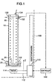
- Fig. 1 is a side view of the whole structure of the separating and picking out apparatus of this embodiment according to the invention.
- a cassette 10 holds a plurality of IC cards 20 therein.
- the cassette 10 is set within a separating and picking out apparatus 100.
- the separating and picking out apparatus 100 is disposed near an IC card marking machine or the like.
- the separating and picking out apparatus 100 also has an elevator mechanism 110 provided therein.
- the elevator mechanism 110 has an arm 112 that is movable up and down in the Z-direction.
- the arm 112 has a pusher 114 provided at its tip.
- the pusher 114 can be inserted in the inside of the cassette 10 because of having a smaller size than the inner diameter of the cassette 10.
- the pusher 114 can engage with the IC cards 20 as thin board type objects within the cassette 10 or with a protective plate that is located under the lowest one of the IC cards, pushing the IC cards 20 upward so that they can be taken out one by one.
- the separating and picking out apparatus 100 also has fixed rollers 120, 122.
- the fixed rollers 120, 122 are pressed against cassette fixing holes 16 that are provided in the cassette 10.
- the cassette 10 is fixedly positioned within the separating and picking out apparatus 100.
- the separating and picking out apparatus 100 also has a ratchet 130 and a pedestal 132.
- the ratchet 130 and pedestal 132 are inserted in the cassette 10 at the upper portion of the cassette 10.
- Use of the ratchet 130 and pedestal 132 can allow a plurality of IC cards 20 to be shifted in the horizontal direction. Under this condition, the suction pad 134 sticks fast to the top, IC card, thus separating that IC card from the other IC cards.
- the detailed structures of the ratchet 130 and pedestal 132 will be described later with reference to Fig. 3.
- the ratchet 130 has a light emitting device, and the pedestal 132 has a photo sensor.
- a signal generated from the photo sensor is received by a controller 140.
- the controller 140 controls the elevator mechanism 110 to locate the top, IC card 20 at the top of the cassette 10.
- Fig. 2 is a perspective view of the structure of the cassette 10 to be used in the apparatus of this embodiment according to the invention.
- the cassette 10 is formed in a rectangular pipe shape by bending an iron thin plate, for example, SPC.
- the cassette 10 is formed not to have any projections on its surfaces.
- the IC cards as thin board type objects to be placed within the cassette 10 are, for example, 85.6 mm long, 54.0 mm wide, 0.45 to 0.76 mm thick.
- the cassette 10 can hold 1000 sheets of IC cards of which the thickness is 0.45 mm, and its total length L1 is 500 mm.
- the cassette 10 has an enough size to smoothly accept the IC cards.
- the gap between the inner wall of the cassette and all the sides of the IC cards is about 1 mm.
- the length L2 of the cross-section of the cassette 10 is 88 mm, and the width L3 thereof is 56 mm. If gaps of 0.5 mm or above can be left between these dimensions and those of the IC cards, there is no particular problem.
- the wall thickness t of the cassette 10 is 2mm.
- the surfaces of the cassette 10 are plated with zinc for rust protection.
- the cassette 10 have stopping holes 12 formed in the side walls. Eighteen groups of stopping holes 12 are formed at a pitch P of 27 mm in the longitudinal direction of the cassette 10. Four stopping holes 12a, 12b, 12c and 12d are formed as each group at the same level in the longitudinal direction. Four ratchets provided on a stopper are engaged with these stopping holes 12a, 12b, 12c and 12d, so that the stopper can be fixed to the cassette 10.
- the cassette 10 also has bent tabs 14a, 14b, 14c and 14d formed at the four corners of its bottom. A protective plate is placed on these bent tabs 14, and the IC cards as thin board type objects are piled up on the plate, thus being prevented from falling out through the bottom of the cassette 10.
- cassette fixing holes 16a, 16b and 16c are formed in the bottom side walls of the cassette 10.
- the cassette 10 is used to hold and carry thin board type objects.
- the cassette 10 can be directly set on an IC card recorder or marking machine.
- the fixing holes 16a, 16b and 16c are used for fixing the cassette 10.
- the fixing roller 120 is pressed against the cassette fixing hole 16a, and the fixing roller 122 against the fixing holes 16b, 16c so that the cassette 10 is positioned and fixed within the apparatus 100.
- an arm insertion window 18 is provided in one side of the cassette 10.
- the arm 112 of the elevator mechanism 110 is inserted in the arm insertion window 18.
- the arm 112 is free to move up and down within the cassette 10.
- the pedestal 132 shown in Fig. 1 is inserted in the arm insertion window 18.
- a window 19 is also formed in the side of the upper portion of cassette 10 to oppose the arm insertion window.
- the window 19 is provided to accept the ratchet 130 of the apparatus 100.
- Fig. 3 is an enlarged side view of the main part of the apparatus of the embodiment according to the invention.
- Fig. 4 is an enlarged plan view of the main part of the apparatus of the embodiment according to the invention.
- a plurality of IC cards 20 are stored in the cassette 10.
- the tip of the ratchet 130 of the apparatus 100 is inserted through the window 19 into the cassette 10.
- the ratchet 130 has a slope 130A provided on its lower side.
- the slope 130A acts to block the IC cards 20 from being moved up (in the Z-direction in the figure) from below, and mechanically shift the upper IC cards 20A, 20B, 20C in the longitudinal direction (X-direction in the figure) of the IC cards 20. Therefore, the ratchet 30 functions as a projection or mover for the IC cards 20.
- the ratchet 130 also has communicating apertures B1, B2, B3, B4 for air-blow.
- the air-blow communicating apertures B1, B2, B3, B4 are provided at positions that are deviated above relative to the center line that intersects with the lateral sides of the IC cards 20 as shown in Fig. 4.
- the air-blow communicating apertures B1, B2, B3, B4 have their one ends opened relative to the slope 130A of the ratchet 130, and their other ends connected to an air blower 136.
- the air compressed by the blower 136 is blown out from the openings of the air blow communicating apertures B1, B2, B3, B4 that are formed in the slope 130A of ratchet 130.
- the air blown out from the openings hits the edges of the IC cards 20A, 20B, 20C shifted by the slope 130A and is blown into the gaps between those edges, thereby separating the IC cards 20A, 20B, 20C.
- the gas blown out from the openings of the air flow communicating apertures B1, B2, B3, B4 may be any kinds of gas other than air.
- the kinds of gas are selected according to the kinds of thin board type objects. Hereinafter, we treats air as a gas.
- the tip of the pedestal 132 of the apparatus 100 is inserted into the cassette 10 through the arm insertion window 18 provided on the side of cassette 10 shown in Fig. 2.
- the pedestal 132 has a slope 132A provided at its upper side to oppose the slope 130A of the ratchet 130.
- the slope 132A acts to keep the IC cards 20 shifted by the slope 130A of ratchet 130 be left as they are. Therefore, the pedestal 132 functions as a recess or as a movement acceptor.
- the top, IC card 20A separated from the other IC cards by the slope 130A and the air blow is attracted and picked out by the Suction pad 134.
- the suction pad 134 is, as shown in Fig. 4, disposed below the center line relative to the lateral sides of the IC card 20, or at the position deviated in the opposite direction to the openings of the air blow communicating apertures B1, B2, B3, B4. In other words, the suction pads 134 is provided at a diagonal position relative to the air blow openings.
- the suction pad 134 is tilted to the direction in which the IC cards 20 are piled up, or to the Z-direction in the figure. If the suction pad 134 lifts the top, IC card 20A together with the next IC card 20B, the brush 138 mounted on the pedestal 132 comes in contact with the edge of the next IC card 20B, causing the IC card 20B to fall by scratching. Thus, only the IC card 20A can be picked out.
- the brush 138 functions to prevent the under IC card 20B from beginning to fly out together with the top, IC card 20A.
- the ratchet 130 of the apparatus 100 has a light emitting device 150, such as a light emitting diode, provided on its top.
- the pedestal 132 has a photo sensor 150, such as a photosensitive diode, provided to oppose the light emitting device 150.
- the light emitting device 150 and the photo sensor 152 constitute a position detecting sensor.
- the photo sensor 152 always receives the light emitted from the light emitting device 150.
- the top, IC card 20A obstructs the light path through which the light from the light emitting device 150 passes to the photo sensor 152. Then, the photo sensor 152 generates a signal indicating that it cannot receive the light from the light emitting device.
- the signal from the photo sensor 152 is supplied to the controller 140.
- the controller 140 controls the elevator mechanism 110 to stop in response to the signal from the photo sensor 152. Consequently, the elevator mechanism 110 is controlled so that the top, IC card of the IC cards 20 can be located at a predetermined position.
- the ratchet 130 and pedestal 132 are made of a metal material such as SUS or aluminum.
- the length L4 of the projection of the ratchet 130 is selected to be 10 mm if the longitudinal length of the IC cards 20 is assumed to be 85.6 mm. If the projection size L4 is too short, two stuck IC cards cannot be sometimes mechanically shifted enough. This aspect will be described later with reference to Fig. 8.
- the distance between the ratchet 130 and pedestal 132 is adjusted to substantially equal to the size of IC card 20.
- the distance L6 between the ratchet 130 and pedestal 132 is selected to be, for example, 86 mm.
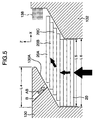
- the ratchet 130 has the slope 130A on its under-side.
- the slope 130A blocks the IC cards 20 from moving up from below (in the Z-direction in the figure).
- the slope 130A serves to mechanically shift the overlapped upper IC cards 20A, 20B, 20C in turn in the longitudinal direction of the IC cards 20 (in the X-direction, or in the horizontal direction in the figure).
- the ratchet 130 also has the air blow communicating aperture B.
- the air blow communicating aperture B has its one end opened to the slope 130A of ratchet 130, and its other end connected to the blower.
- the air compressed by the blower is blown out from the opening of the air blow communicating aperture that is provided in the slope 130A of the ratchet 130.
- the blown air hits the edges of the IC cards 20A, 20B, 20C shifted by the slope 130A and is blown into the gaps between those edges, thereby separating the IC cards 20A, 20B, 20C.
- a position detecting sensor is provided that is constituted by the light emitting device 150 and photo sensor 152.
- the controller 140 controls the elevator mechanism 110 so that the top, IC card 20A comes at near the air blow opening of the ratchet 130.
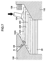
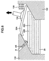
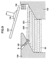
- the four air blow communicating apertures B1, B2, B3, B4 are provided as in Figs. 3 and 4, only one thereof is shown as the air blow communicating aperture B in Figs. 5 through 9.
- the suction pad 134 mounted tilted, as illustrated in Fig. 7, is pushed against the IC card 20 at a position deviated from the center of the IC card 20, particularly at a diagonal position relative to the air blow outlet as shown in Fig. 3, thus sticking fast to the top, IC card 20A. Therefore, the IC card 20A separated from the IC card 20B by air blow can be prevented from being again stuck to the under IC card 20B by the pushing force the suction pad 134 exerts.
- the projection size L4 of the ratchet 130 is selected to 10 mm, the two stuck IC cards are greatly bent by the tip of the projection. Therefore, the suction pad 134 is stopped from being lifted, and the two stuck IC cards are left bent for a while. Then, the stuck IC cards will be naturally separated, and as a result the under IC card 20B falls.
- the IC card 20A bent by touching the ratchet 130 passes away from the ratchet 130, and is then restored to the original flat shape.
- the IC card 20A can be completely picked out.
- the suction pad 134 is lifted, the edge of the IC card 20A is rubbed by the brush 138. Therefore, even if the IC card 20B is lifted together with the IC card 20A in a stuck state when the suction pad 134 fast sticks to the top, IC card 20A, the edges of the IC cards 20A, 20B are rubbed by the brush 138.
- the under IC card 20B is scratched down by the brush 138 to fall away from the IC card 20A as well. Consequently, only the IC card 20A attracted by the suction pad 134 can be picked out.
- the brush 138 prevents the under IC card 20B from flying away to the outside.
- the controller 140 controls the elevator mechanism 110 to operate, thus raising the IC cards held within the cassette 10.
- the controller 140 stops the operation of the elevator mechanism 110 as we described previously. Then, as with the IC card 20A, the apparatus 100 picks out the IC card 20B.
- the slope 130A of the ratchet 130 in the apparatus 100 of this embodiment is used to mechanical shift the overlapped and stuck thin board type objects, such as IC cards, in the horizontal direction. Therefore, the thin board type objects, even when firmly stuck together, can be effectively separated from each other.
- top side picking out type since the top side picking out type is employed, it is not necessary to adjust the gap between the rollers unlike the bottom side picking out type even when the thin board type objects like IC cards that have different thickness are picked out.
- the suction pad 134 is pushed against the top, thin object, such as the top, IC card, at a position deviated from the center of the surface of the object. This position is diagonal to the air blow outlet. Therefore, the thin board type object pressed down by the suction pad does not again stick to the underlying body.
- the suction pad 134 is pressed against the thin board type objects in a tilted direction relative to the direction in which the thin board type objects are piled up. Therefore, the top, object can be prevented from again sticking to the under object.
- the overlapped objects are separated by horizontally shifting those objects and blowing air into the gap between the edges thereof. Then, this separating and picking out apparatus picks out each thin board type object by use of the suction pad. Therefore, the apparatus of this embodiment is able to precisely separate the thin board type objects, such as IC cards, that tend to firmly stick to each other, into each one, and fast pick it out. Moreover, different kinds of objects with different thickness can be correctly treated by the same mechanism, and thus the apparatus of this embodiment is versatile.
Landscapes
- Engineering & Computer Science (AREA)
- Mechanical Engineering (AREA)
- Sheets, Magazines, And Separation Thereof (AREA)
- De-Stacking Of Articles (AREA)
Abstract
Description
Claims (15)
- An apparatus (100) for separating and picking out one of a plurality of piled up thin board type objects (20), comprising:a projection (130) provided above said plurality of piled up thin board type objects (20), said projection being made in contact with upper ones of said thin board type objects moved up from below, to thereby move each of said contacted objects in the horizontal direction; anda suction pad (134) provided above said plurality of piled up thin board type objects, said suction pad sticking fast to and picking out the top of said upper objects horizontally moved by said projection.
- An apparatus according to claim 1, further comprising:a gas blow outlet (136, B) from which gas is blown into at least a gap between a first one, or said top and a second one just under said first object, of said upper objects horizontally moved by said projection.
- An apparatus according to claim 1, wherein said suction pad sticks fast to the surface of said first object piled on top, at a position deviated away from its center.
- An apparatus according to claim 1, wherein said projection has a slope (130A) provided to come in contact with said objects, said slope having a gradient relative to the horizontal direction of said objects so that said objects, when moved up from below, are sequentially made in contact with said slope to thereby be moved in the horizontal direction.
- An apparatus according to claim 2, wherein said projection has a slope (130A) provided to come in contact with said objects, said slope having a gradient relative to the horizontal direction of said objects so that said objects, when moved up from below, are sequentially made in contact with said slope to thereby be moved in the horizontal direction, and said gas blow outlet is provided in said slope.
- An apparatus according to claim 1, further comprising a recess (132) provided above said plurality of piled up thin board type objects to oppose said projection, wherein said projection having a light emitting device (150), and said recess has a photo sensor (152) for receiving light emitted from said light emitting device so that said photo sensor detects whether the light emitted from said light emitting device is blocked by said objects or not.
- An apparatus according to claim 6, further comprising:an elevator (110) for lifting said plurality of piled up objects; anda controller (140) for controlling the operation of said elevator,
wherein said photo sensor generates a signal when detecting that the light emitted from said light emitting device is blocked by said objects, and said controller receives said signal generated from said photo sensor, and stops said elevator from lifting. - An apparatus according to claim 1, further comprising a recess (132) provided above said plurality of piled up objects to oppose said projection, wherein said recess has a flying-away preventing device (138) for preventing said objects other than said object attracted by said suction pad from flying away.
- An apparatus according to claim 8, wherein said flying-away preventing device is like a brush.
- An apparatus according to claim 3, wherein the absorbing surface of said suction pad is tilted relative to the horizontal direction of said objets, said suction pad being pushed against said object with said tilt kept, to stick fast to said object.
- An apparatus (100) for separating and picking out one of a plurality of piled up thin board type objects (20), comprising:moving means (130) for moving each of said objects in the horizontal direction by touching said objects moved up from below; andsuction means (134) for sticking fast to the top of said objects horizontally moved by said moving means, and picking out it.
- An apparatus according to claim 11, further comprising a gas blow outlet (136, B) from which gas is blown into at least a gap between a first one, or said top and a second one just under said first object, of said objects horizontally moved by said moving means.
- An apparatus according to claim 11, wherein said suction means sticks fast to the surface of said top at a position deviated from its center.
- An apparatus according to claim 11, further comprising:elevating means (110) for lifting said plurality of piled up objects;control means (140) for controlling the operation of said elevator;light emitting means (150) for emitting light; andphoto sensitive means (152) for receiving light generated from said light emitting means,
wherein said photo sensitive means generates a signal when detecting that the light emitted from said light emitting device is blocked by said object, and said control means receives said signal emitted from said photo sensitive means and stops said elevator from lifting. - A method for separating and picking out one of a plurality of piled up thin board type objects (20), comprising the steps of:moving said objects up from below;moving said objects in piled-up order in the horizontal direction;blowing gas into at least a gap between a first one, or top and a second one just under said first object, of said objects horizontally moved; andsticking fast to the surface of said top at a position deviated from its center, and picking out said top.
Applications Claiming Priority (2)
| Application Number | Priority Date | Filing Date | Title |
|---|---|---|---|
| JP20342799 | 1999-07-16 | ||
| JP11203427A JP2001026321A (en) | 1999-07-16 | 1999-07-16 | Separation cutting device |
Publications (2)
| Publication Number | Publication Date |
|---|---|
| EP1070674A2 true EP1070674A2 (en) | 2001-01-24 |
| EP1070674A3 EP1070674A3 (en) | 2002-04-17 |
Family
ID=16473913
Family Applications (1)
| Application Number | Title | Priority Date | Filing Date |
|---|---|---|---|
| EP00305898A Withdrawn EP1070674A3 (en) | 1999-07-16 | 2000-07-12 | Apparatus for separating and picking out thin board type objects |
Country Status (2)
| Country | Link |
|---|---|
| EP (1) | EP1070674A3 (en) |
| JP (1) | JP2001026321A (en) |
Cited By (5)
| Publication number | Priority date | Publication date | Assignee | Title |
|---|---|---|---|---|
| US7954624B2 (en) | 2006-05-16 | 2011-06-07 | Rorze Corporation | Shuttle type conveying device, microplate feeding and collecting device, pickup device for microplate, cassette for microplate, and shelf for containing microplate |
| CN103395641A (en) * | 2013-07-31 | 2013-11-20 | 钜鼎(扬州)光电显示科技有限公司 | Diaphragm separating and grabbing device and diaphragm separating and grabbing method |
| CN113682592A (en) * | 2021-09-03 | 2021-11-23 | 林州致远电子科技有限公司 | Technical method for preventing cushion pad from adhesion |
| CN115092699A (en) * | 2022-07-19 | 2022-09-23 | 合肥固泰自动化有限公司 | Defeated spacing platform of plastic of transfusing of cement wrapping bag of sticking with paste end |
| CN116924113A (en) * | 2023-07-04 | 2023-10-24 | 东莞市彤光电子科技有限公司 | Monolithic feeding device for improving feeding speed of transparent film material |
Families Citing this family (7)
| Publication number | Priority date | Publication date | Assignee | Title |
|---|---|---|---|---|
| JP4552846B2 (en) * | 2005-12-21 | 2010-09-29 | パナソニック電工株式会社 | Plate material suction transfer device and method |
| CN103057983B (en) * | 2013-01-21 | 2015-12-02 | 广州华工环源绿色包装技术有限公司 | Paper mould product disengagement gear |
| JP6819986B2 (en) * | 2016-06-30 | 2021-01-27 | 株式会社ワールドベンチャー | Automatic continuous image engraving device |
| KR102346333B1 (en) | 2016-06-30 | 2021-12-31 | 가부시키가이샤 월드 벤처 | Automatic continuous image engraving device |
| JP7272301B2 (en) * | 2019-09-27 | 2023-05-12 | 株式会社デンソー | clipping device |
| JP2021079476A (en) * | 2019-11-18 | 2021-05-27 | 興和株式会社 | Work sorting system and work sorting robot |
| CN115922184B (en) * | 2023-03-15 | 2023-05-05 | 长春华翔汽车金属部件有限公司 | Thermoforming patch board welding workstation |
Family Cites Families (3)
| Publication number | Priority date | Publication date | Assignee | Title |
|---|---|---|---|---|
| US4003567A (en) * | 1976-04-07 | 1977-01-18 | Union Camp Corporation | Sheet pick-up and feeder |
| GB1561264A (en) * | 1976-10-05 | 1980-02-20 | Htb Ltd | Sheet feeding machines |
| JP2536968B2 (en) * | 1990-12-20 | 1996-09-25 | 川崎製鉄株式会社 | A device for preventing double hanging of stacked thin plates |
-
1999
- 1999-07-16 JP JP11203427A patent/JP2001026321A/en active Pending
-
2000
- 2000-07-12 EP EP00305898A patent/EP1070674A3/en not_active Withdrawn
Cited By (8)
| Publication number | Priority date | Publication date | Assignee | Title |
|---|---|---|---|---|
| US7954624B2 (en) | 2006-05-16 | 2011-06-07 | Rorze Corporation | Shuttle type conveying device, microplate feeding and collecting device, pickup device for microplate, cassette for microplate, and shelf for containing microplate |
| US8118153B2 (en) | 2006-05-16 | 2012-02-21 | Rorze Corporation | Shuttle-type conveying device, microplate feeding and collecting device, pickup device for microplate, cassette for microplate, and shelf for containing microplate |
| CN103395641A (en) * | 2013-07-31 | 2013-11-20 | 钜鼎(扬州)光电显示科技有限公司 | Diaphragm separating and grabbing device and diaphragm separating and grabbing method |
| CN103395641B (en) * | 2013-07-31 | 2015-10-28 | 许翔 | Diaphragm burst and grabbing device and the grasping means of diaphragm burst |
| CN113682592A (en) * | 2021-09-03 | 2021-11-23 | 林州致远电子科技有限公司 | Technical method for preventing cushion pad from adhesion |
| CN115092699A (en) * | 2022-07-19 | 2022-09-23 | 合肥固泰自动化有限公司 | Defeated spacing platform of plastic of transfusing of cement wrapping bag of sticking with paste end |
| CN115092699B (en) * | 2022-07-19 | 2023-11-21 | 合肥固泰自动化有限公司 | Conveying and shaping limiting platform for paste bottom cement packaging bag |
| CN116924113A (en) * | 2023-07-04 | 2023-10-24 | 东莞市彤光电子科技有限公司 | Monolithic feeding device for improving feeding speed of transparent film material |
Also Published As
| Publication number | Publication date |
|---|---|
| JP2001026321A (en) | 2001-01-30 |
| EP1070674A3 (en) | 2002-04-17 |
Similar Documents
| Publication | Publication Date | Title |
|---|---|---|
| EP1070674A2 (en) | Apparatus for separating and picking out thin board type objects | |
| EP0035890A1 (en) | A system and method for controlling the relative positioning of two objects such as an article handling vehicle and a storage location | |
| JPH0464275B2 (en) | ||
| JPS61273441A (en) | Wafer transfer device | |
| CN118083435A (en) | A slide assembly and distribution wall | |
| EP0109991B1 (en) | Gravity feed chute | |
| CN100430688C (en) | Inclination detection method and inclination detection device | |
| JPS61248839A (en) | Takeout device for housed wafer | |
| JPH05246608A (en) | Actuator device for sheet-detection | |
| JPH06171802A (en) | Flexible substrate supplier | |
| US6776338B2 (en) | IC card reader | |
| EP0129599A1 (en) | Method and apparatus for handling magnetic recording disks | |
| JPH08157123A (en) | Aligning stacking device for work body | |
| JPH0839447A (en) | Screw aligner | |
| KR100438095B1 (en) | Automatic Medal Transfer Device For Vending Machine, By Using Medal Processing Printer | |
| JPH07320382A (en) | Disc player | |
| JPH0817199B2 (en) | Wafer transfer device | |
| JP2873071B2 (en) | Prize dispensing machine | |
| JPH09272095A (en) | Plate-shaped object conveying robot | |
| JP2000100921A (en) | Semiconductor substrate carrier and method of manufacturing semiconductor device | |
| JP2001097557A (en) | Tray separating apparatus | |
| JP2002261144A (en) | Substrate delivery method and apparatus | |
| JP2520919B2 (en) | Probe device | |
| CN219098065U (en) | Carrying device is inhaled to subregion magnetism | |
| JP2500205B2 (en) | Wafer transfer device |
Legal Events
| Date | Code | Title | Description |
|---|---|---|---|
| PUAI | Public reference made under article 153(3) epc to a published international application that has entered the european phase |
Free format text: ORIGINAL CODE: 0009012 |
|
| 17P | Request for examination filed |
Effective date: 20000801 |
|
| AK | Designated contracting states |
Kind code of ref document: A2 Designated state(s): AT BE CH CY DE DK ES FI FR GB GR IE IT LI LU MC NL PT SE Kind code of ref document: A2 Designated state(s): DE FR GB |
|
| AX | Request for extension of the european patent |
Free format text: AL;LT;LV;MK;RO;SI |
|
| PUAL | Search report despatched |
Free format text: ORIGINAL CODE: 0009013 |
|
| AK | Designated contracting states |
Kind code of ref document: A3 Designated state(s): AT BE CH CY DE DK ES FI FR GB GR IE IT LI LU MC NL PT SE |
|
| AX | Request for extension of the european patent |
Free format text: AL;LT;LV;MK;RO;SI |
|
| RIC1 | Information provided on ipc code assigned before grant |
Free format text: 7B 65H 3/08 A, 7B 65H 3/48 B, 7B 65H 1/22 B |
|
| AKX | Designation fees paid |
Free format text: DE FR GB |
|
| 17Q | First examination report despatched |
Effective date: 20030331 |
|
| STAA | Information on the status of an ep patent application or granted ep patent |
Free format text: STATUS: THE APPLICATION IS DEEMED TO BE WITHDRAWN |
|
| 18D | Application deemed to be withdrawn |
Effective date: 20030812 |