EP1070663B1 - Drive system for a tiltrotor aircraft - Google Patents
Drive system for a tiltrotor aircraft Download PDFInfo
- Publication number
- EP1070663B1 EP1070663B1 EP00115465A EP00115465A EP1070663B1 EP 1070663 B1 EP1070663 B1 EP 1070663B1 EP 00115465 A EP00115465 A EP 00115465A EP 00115465 A EP00115465 A EP 00115465A EP 1070663 B1 EP1070663 B1 EP 1070663B1
- Authority
- EP
- European Patent Office
- Prior art keywords
- gears
- propeller
- power plant
- pair
- gear
- Prior art date
- Legal status (The legal status is an assumption and is not a legal conclusion. Google has not performed a legal analysis and makes no representation as to the accuracy of the status listed.)
- Expired - Lifetime
Links
Images
Classifications
-
- B—PERFORMING OPERATIONS; TRANSPORTING
- B64—AIRCRAFT; AVIATION; COSMONAUTICS
- B64D—EQUIPMENT FOR FITTING IN OR TO AIRCRAFT; FLIGHT SUITS; PARACHUTES; ARRANGEMENTS OR MOUNTING OF POWER PLANTS OR PROPULSION TRANSMISSIONS IN AIRCRAFT
- B64D35/00—Transmitting power from power plant to propellers or rotors; Arrangements of transmissions
-
- B—PERFORMING OPERATIONS; TRANSPORTING
- B64—AIRCRAFT; AVIATION; COSMONAUTICS
- B64C—AEROPLANES; HELICOPTERS
- B64C27/00—Rotorcraft; Rotors peculiar thereto
- B64C27/22—Compound rotorcraft, i.e. aircraft using in flight the features of both aeroplane and rotorcraft
- B64C27/28—Compound rotorcraft, i.e. aircraft using in flight the features of both aeroplane and rotorcraft with forward-propulsion propellers pivotable to act as lifting rotors
-
- B—PERFORMING OPERATIONS; TRANSPORTING
- B64—AIRCRAFT; AVIATION; COSMONAUTICS
- B64C—AEROPLANES; HELICOPTERS
- B64C29/00—Aircraft capable of landing or taking-off vertically, e.g. vertical take-off and landing [VTOL] aircraft
- B64C29/0008—Aircraft capable of landing or taking-off vertically, e.g. vertical take-off and landing [VTOL] aircraft having its flight directional axis horizontal when grounded
- B64C29/0016—Aircraft capable of landing or taking-off vertically, e.g. vertical take-off and landing [VTOL] aircraft having its flight directional axis horizontal when grounded the lift during taking-off being created by free or ducted propellers or by blowers
- B64C29/0033—Aircraft capable of landing or taking-off vertically, e.g. vertical take-off and landing [VTOL] aircraft having its flight directional axis horizontal when grounded the lift during taking-off being created by free or ducted propellers or by blowers the propellers being tiltable relative to the fuselage
-
- Y—GENERAL TAGGING OF NEW TECHNOLOGICAL DEVELOPMENTS; GENERAL TAGGING OF CROSS-SECTIONAL TECHNOLOGIES SPANNING OVER SEVERAL SECTIONS OF THE IPC; TECHNICAL SUBJECTS COVERED BY FORMER USPC CROSS-REFERENCE ART COLLECTIONS [XRACs] AND DIGESTS
- Y10—TECHNICAL SUBJECTS COVERED BY FORMER USPC
- Y10T—TECHNICAL SUBJECTS COVERED BY FORMER US CLASSIFICATION
- Y10T74/00—Machine element or mechanism
- Y10T74/19—Gearing
- Y10T74/19014—Plural prime movers selectively coupled to common output
-
- Y—GENERAL TAGGING OF NEW TECHNOLOGICAL DEVELOPMENTS; GENERAL TAGGING OF CROSS-SECTIONAL TECHNOLOGIES SPANNING OVER SEVERAL SECTIONS OF THE IPC; TECHNICAL SUBJECTS COVERED BY FORMER USPC CROSS-REFERENCE ART COLLECTIONS [XRACs] AND DIGESTS
- Y10—TECHNICAL SUBJECTS COVERED BY FORMER USPC
- Y10T—TECHNICAL SUBJECTS COVERED BY FORMER US CLASSIFICATION
- Y10T74/00—Machine element or mechanism
- Y10T74/19—Gearing
- Y10T74/19023—Plural power paths to and/or from gearing
- Y10T74/19074—Single drive plural driven
- Y10T74/19079—Parallel
- Y10T74/19093—Spur and bevel
-
- Y—GENERAL TAGGING OF NEW TECHNOLOGICAL DEVELOPMENTS; GENERAL TAGGING OF CROSS-SECTIONAL TECHNOLOGIES SPANNING OVER SEVERAL SECTIONS OF THE IPC; TECHNICAL SUBJECTS COVERED BY FORMER USPC CROSS-REFERENCE ART COLLECTIONS [XRACs] AND DIGESTS
- Y10—TECHNICAL SUBJECTS COVERED BY FORMER USPC
- Y10T—TECHNICAL SUBJECTS COVERED BY FORMER US CLASSIFICATION
- Y10T74/00—Machine element or mechanism
- Y10T74/19—Gearing
- Y10T74/19628—Pressure distributing
Definitions
- the present invention relates to a power plant for propeller aircraft.
- a power plant according to the preamble of claim 1 is known from DE 39 17 499 A.
- Aircraft are known which are powered by a power plant comprising two propeller devices, each of which in turn comprises an engine, a propeller, and a gear transmission interposed between the engine and the propeller and having an output shaft to which the propeller is fitted.
- Each propeller device rotates, about a substantially horizontal axis, between a first work position in which the respective output shaft is vertical and the propellers permit vertical takeoff of the aircraft in the same way as a helicopter, and a second work position in which the output shaft extends substantially horizontally and the propellers permit forward flight of the aircraft.
- the two propeller devices are connected by a countershaft, so that, in the event either of the engines breaks down, the other provides for rotating both propellers.
- a power plant for propeller aircraft comprising two propulsion devices; each propulsion device comprising a respective propeller, a respective engine for powering the propeller, and a gear transmission interposed between the engine and the propeller and comprising a power input shaft connected directly to said engine, and a power output shaft supporting said propeller and rotated with respect to said input shaft about a hinge axis substantially perpendicular to the output shaft characterized by said gear transmission also comprising a single gear fitted to said output shaft and comprising two opposed sets of teeth, a pair of pinions, each meshing with a respective said set of teeth, and, for each said pinion, a single respective gear meshing directly with the gear of the other pinion; and in that one of said pinions is disposed coaxially with said hinge axis, and is connected to said input shaft by a single pair of gears.
- the gears in said single pair of gears are preferably bevel gears.
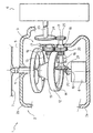
- Number 1 in the accompanying drawing indicates as a whole a power plant for a propeller aircraft (not shown).
- the power plant comprises a frame 2, in turn comprising a structure 2a fixed to a frame of the aircraft (not shown, for the sake of simplicity), and a movable structure 2b connected to structure 2a by a known hinge assembly (not shown) so as to rotate with respect to structure 2a about a fixed hinge axis 3.
- power plant 1 comprises two identical propulsion devices 5 and 6, one of which is shown partly in section, and the other schematically.
- Each device is normally connected to a wing of the aircraft, and comprises a respective propeller 7, a respective engine 8 for powering propeller 7 and connected integrally to fixed structure 2a, and a gear transmission 9 interposed between engine 8 and propeller 7.
- Transmission 9 comprises a power input shaft 10 connected directly in known manner to engine 8 and perpendicular to hinge axis 3; and a power output shaft 11, which extends perpendicular to hinge axis 3, is connected in rotary and axially-fixed manner to movable structure 2b, projects outwards through structure 2b, and is fitted in known manner with propeller 7.
- Each transmission 9 also comprises a single gear 12, preferably a face gear, fitted to output shaft 11 and having two opposite rings of teeth 13 and 14; and a single pair of pinions 15 and 16 located on opposite axial sides of gear 12 and each meshing with a respective ring of teeth 13, 14. Pinions 15 and 16 are fitted to respective parallel shafts 17 and 18, which are also fitted with respective identical, mutually meshing spur gears 19 and 20.
- Shaft 18 extends coaxially with hinge axis 3, and is connected to input shaft 10 by a single pair of bevel gears 21 and 22, preferably face gears, one of which is fitted to shaft 18 and the other to input shaft 10.
- the power plant also comprises a countershaft 23, which extends between the transmissions, eccentrically with respect to hinge axis 3, and is connected to each of shafts 18 by a single pair of spur gears 24 and 25, one of which is fitted to shaft 23 and the other to shaft 18, on the opposite side of respective pinion 16 with respect to respective bevel gear 21.
- structure 2b can be rotated, with respect to respective structure 2a, about respective hinge axis 3 to rotate output shaft 11, gear 12 and pinion 15 - which rotates in contact with pinion 16 - into a position in which output shaft 11 is substantially horizontal and propeller 7 moves the aircraft forward.
- Transmissions 9 described therefore not only provide for rotating shafts 11 of propellers 7, with respect to respective engines 8, about substantially horizontal axes 3, while leaving engines 8 stationary, but are also extremely lightweight and cheap to produce.
- This is substantially due to the fact that, in each device, a single gear 12 meshing with a single pair of pinions 15 and 16 is interposed between respective input shaft 10 and respective output shaft 11, and, above all, to the fact that one of the pinions is connected to engine 8 by a single pair of gears 21 and 22, and is also connected to the corresponding pinion on the other device by a single pair of conveniently spur gears 24 and 25.
- the presence of an extremely small number of gears and, in particular, of gears movable together with structure 2b provides, with respect to known solutions, for considerably reducing the force required to rotate the output shaft between said operating positions.
- bevel gears may be replaced by a different pair of gears, and the spur gears replaced by other, e.g. bevel, gears.
Abstract
Description
- The present invention relates to a power plant for propeller aircraft. A power plant according to the preamble of
claim 1 is known from DE 39 17 499 A. - Aircraft are known which are powered by a power plant comprising two propeller devices, each of which in turn comprises an engine, a propeller, and a gear transmission interposed between the engine and the propeller and having an output shaft to which the propeller is fitted. Each propeller device rotates, about a substantially horizontal axis, between a first work position in which the respective output shaft is vertical and the propellers permit vertical takeoff of the aircraft in the same way as a helicopter, and a second work position in which the output shaft extends substantially horizontally and the propellers permit forward flight of the aircraft.
- In most applications, the two propeller devices are connected by a countershaft, so that, in the event either of the engines breaks down, the other provides for rotating both propellers.
- Though widely used, known power plants of the above type leave considerable room for improvement, on account of the considerable force required and the relatively long time taken to rotate between said two positions, mainly due to the weight of the components for rotation.
- Solutions are known in which the engines remain stationary with respect to the aircraft. Such solutions, however, only provide for partly solving the problem, on account of most of the components of each propeller device still being rotated about the respective horizontal axis. Moreover, the movement of the propeller with respect to the relative engine makes the transmission extremely complex, expensive, and, in some case, heavier than movable-engine transmissions.
- It is an object of the present invention to provide a power plant for propeller aircraft, designed to provide a straightforward, low-cost solution to the problems typically associated with the known state of the art.
- According to the present invention, there is provided a power plant for propeller aircraft, comprising two propulsion devices; each propulsion device comprising a respective propeller, a respective engine for powering the propeller, and a gear transmission interposed between the engine and the propeller and comprising a power input shaft connected directly to said engine, and a power output shaft supporting said propeller and rotated with respect to said input shaft about a hinge axis substantially perpendicular to the output shaft characterized by said gear transmission also comprising a single gear fitted to said output shaft and comprising two opposed sets of teeth, a pair of pinions, each meshing with a respective said set of teeth, and, for each said pinion, a single respective gear meshing directly with the gear of the other pinion; and in that one of said pinions is disposed coaxially with said hinge axis, and is connected to said input shaft by a single pair of gears.
- The gears in said single pair of gears are preferably bevel gears.
- This therefore provides for obtaining a power plant for propeller aircraft, in which the propellers rotate with respect to the aircraft, while the respective engines remain stationary, and in which the loads involved in effecting rotation are considerably reduced, thus permitting faster, more reliable rotation of the propellers with respect to the aircraft.
- Moreover, the gear transmission of the power plant according to' the invention is considerably reduced with respect to that of the known state of the art, thus reducing the weight of the power plant as a whole.
- A non-limiting embodiment of the present invention will be described by way of example with reference to the accompanying drawing, which shows an overall view in perspective of the power plant according to the present invention.
-
Number 1 in the accompanying drawing indicates as a whole a power plant for a propeller aircraft (not shown). The power plant comprises aframe 2, in turn comprising astructure 2a fixed to a frame of the aircraft (not shown, for the sake of simplicity), and amovable structure 2b connected tostructure 2a by a known hinge assembly (not shown) so as to rotate with respect tostructure 2a about a fixed hinge axis 3. - With reference to the accompanying drawing,
power plant 1 comprises twoidentical propulsion devices respective propeller 7, arespective engine 8 for poweringpropeller 7 and connected integrally tofixed structure 2a, and a gear transmission 9 interposed betweenengine 8 andpropeller 7. Transmission 9 comprises apower input shaft 10 connected directly in known manner toengine 8 and perpendicular to hinge axis 3; and apower output shaft 11, which extends perpendicular to hinge axis 3, is connected in rotary and axially-fixed manner tomovable structure 2b, projects outwards throughstructure 2b, and is fitted in known manner withpropeller 7. - Each transmission 9 also comprises a
single gear 12, preferably a face gear, fitted tooutput shaft 11 and having two opposite rings ofteeth pinions gear 12 and each meshing with a respective ring ofteeth Pinions parallel shafts spur gears -
Shaft 18 extends coaxially with hinge axis 3, and is connected toinput shaft 10 by a single pair ofbevel gears shaft 18 and the other to inputshaft 10. - As shown in the accompanying drawing, the power plant also comprises a
countershaft 23, which extends between the transmissions, eccentrically with respect to hinge axis 3, and is connected to each ofshafts 18 by a single pair ofspur gears shaft 23 and the other toshaft 18, on the opposite side ofrespective pinion 16 with respect torespective bevel gear 21. - In actual use, as of a first operating position shown in the accompanying drawing, wherein
shafts respective propeller 7 lifts the aircraft,structure 2b can be rotated, with respect torespective structure 2a, about respective hinge axis 3 to rotateoutput shaft 11,gear 12 and pinion 15 - which rotates in contact with pinion 16 - into a position in whichoutput shaft 11 is substantially horizontal andpropeller 7 moves the aircraft forward. - Transmissions 9 described therefore not only provide for rotating
shafts 11 ofpropellers 7, with respect torespective engines 8, about substantially horizontal axes 3, while leavingengines 8 stationary, but are also extremely lightweight and cheap to produce. This is substantially due to the fact that, in each device, asingle gear 12 meshing with a single pair ofpinions respective input shaft 10 andrespective output shaft 11, and, above all, to the fact that one of the pinions is connected toengine 8 by a single pair ofgears spur gears structure 2b, provides, with respect to known solutions, for considerably reducing the force required to rotate the output shaft between said operating positions. - Clearly, changes may be made to the power plant as described herein without, however, departing from the scope of the accompanying Claims. In particular, the bevel gears may be replaced by a different pair of gears, and the spur gears replaced by other, e.g. bevel, gears.
Claims (7)
- A power plant (1) for propeller aircraft, comprising two propulsion devices (5, 6); each propulsion device comprising a respective propeller (7), a respective engine (8) for powering the propeller (7), and a gear transmission (9) interposed between the engine (8) and the propeller (7) and comprising a power input shaft (10) connected directly to said engine (8), and a power output shaft (11) supporting said propeller (7) and rotated with respect to said input shaft (10) about a hinge axis (3) substantially perpendicular to the output shaft (11) characterized by said gear transmission (9) also comprising a single gear (12) fitted to said output shaft (11) and comprising two opposed sets of teeth (13, 14), a pair of pinions (15, 16), each meshing with a respective said set of teeth (13, 14), and, for each said pinion (15, 16), a single respective gear (19, 20) meshing directly with the gear (19, 20) of the other pinion (15, 16) and in that one of said pinions (15, 16) is disposed coaxially with said hinge axis (3), and is connected to said input shaft (10) by a single pair of gears (21, 22).
- A power plant as claimed in Claim 1, characterized in that the gears (21, 22) in said single pair of gears are bevel gears.
- A power plant as claimed in Claim 1 or 2, characterized in that said pair of gears (21, 22) is a pair of face gears.
- A power plant as claimed in Claim 1 or 2, characterized by also comprising a countershaft (23) extending between said two transmissions (9) and connected to one of said pinions (15, 16) of each transmission by a single further pair of gears (24, 25).
- A power plant as claimed in Claim 3, characterized in that one gear in said further pair of gears (24, 25) is disposed coaxially with said hinge axis.
- A power plant as claimed in Claim 3 or 4, characterized in that said countershaft (23) extends eccentrically with respect to said hinge axis (3).
- A power plant as claimed in one of Claims 3 to 5, characterized in that the gears (24, 25) in said further single pair of gears are spur gears.
Applications Claiming Priority (2)
| Application Number | Priority Date | Filing Date | Title |
|---|---|---|---|
| ITTO990648 | 1999-07-20 | ||
| IT1999TO000648A IT1310132B1 (en) | 1999-07-20 | 1999-07-20 | PROPULSION GROUP FOR PROPELLER VEHICLES. |
Publications (3)
| Publication Number | Publication Date |
|---|---|
| EP1070663A2 EP1070663A2 (en) | 2001-01-24 |
| EP1070663A3 EP1070663A3 (en) | 2001-10-04 |
| EP1070663B1 true EP1070663B1 (en) | 2003-09-17 |
Family
ID=11417989
Family Applications (1)
| Application Number | Title | Priority Date | Filing Date |
|---|---|---|---|
| EP00115465A Expired - Lifetime EP1070663B1 (en) | 1999-07-20 | 2000-07-18 | Drive system for a tiltrotor aircraft |
Country Status (7)
| Country | Link |
|---|---|
| US (1) | US6634861B1 (en) |
| EP (1) | EP1070663B1 (en) |
| JP (1) | JP2001063696A (en) |
| AT (1) | ATE249966T1 (en) |
| CA (1) | CA2314570C (en) |
| DE (1) | DE60005261T2 (en) |
| IT (1) | IT1310132B1 (en) |
Families Citing this family (7)
| Publication number | Priority date | Publication date | Assignee | Title |
|---|---|---|---|---|
| FR2830307B1 (en) * | 2001-10-02 | 2003-12-05 | Eurocopter France | ROCKING POWER TRANSMISSION WITH PERIPHERAL FRONT TOOTHING WHEELS OF THE "FAR GEAR" TYPE |
| US7698816B2 (en) * | 2006-06-22 | 2010-04-20 | The Boeing Company | Method of making a pinion meshing with a given face gear in accordance with altered design parameters |
| CN102730193B (en) * | 2012-06-20 | 2014-05-07 | 清华大学 | Helicopter power system and helicopter with system |
| US9278760B2 (en) | 2013-09-04 | 2016-03-08 | Sikorsky Aircraft Corporation | Torque split gearbox for rotary wing aircraft |
| CN103742377A (en) * | 2014-01-07 | 2014-04-23 | 丁兴龙 | Directive force generation device |
| CN108138912A (en) * | 2015-07-21 | 2018-06-08 | 翟柱光 | Zero clearance right-angle drive system and method |
| CN111038695B (en) * | 2019-12-04 | 2022-11-29 | 江西洪都航空工业集团有限责任公司 | Cross-medium aircraft power device |
Family Cites Families (9)
| Publication number | Priority date | Publication date | Assignee | Title |
|---|---|---|---|---|
| US2479406A (en) * | 1946-03-29 | 1949-08-16 | United Aircraft Corp | Bevel gear drive |
| CH388110A (en) * | 1959-10-28 | 1965-02-15 | Aero Consultor Ag | Propeller-driven conversion aircraft with fixed wing |
| CA1017729A (en) * | 1968-09-12 | 1977-09-20 | Evan A. Fradenburgh | Mechanism for synchronously varying diameter of a plurality of rotors and for limiting the diameters thereof |
| DE2903389A1 (en) * | 1978-03-22 | 1979-10-04 | Breinlich Richard Dr | AIRCRAFT WITH PROPELLERS DRIVEN BY FLUID MOTORS, WHICH CAN BE CHANGED IN ITS POSITION |
| DE3917499A1 (en) * | 1989-05-30 | 1990-12-06 | Herbert Zemann | Vertical take-off aircraft - has front and rear propellers which can be swung through 90 deg. NoAbstract |
| DE4422987C2 (en) * | 1994-06-30 | 1996-07-18 | Wilmowsky Freiherr Von Kaspar | Tilt rotor helicopter |
| US5823470A (en) * | 1996-07-16 | 1998-10-20 | Mcdonnell Douglas Helicopter Co. | Split torque proprotor transmission |
| IT1297939B1 (en) * | 1997-12-23 | 1999-12-20 | Fiatavio Spa | GEAR TRANSMISSION GROUP |
| IT1308096B1 (en) * | 1999-06-02 | 2001-11-29 | Finmeccanica Spa | TILTROTOR |
-
1999
- 1999-07-20 IT IT1999TO000648A patent/IT1310132B1/en active
-
2000
- 2000-07-18 EP EP00115465A patent/EP1070663B1/en not_active Expired - Lifetime
- 2000-07-18 AT AT00115465T patent/ATE249966T1/en not_active IP Right Cessation
- 2000-07-18 DE DE60005261T patent/DE60005261T2/en not_active Expired - Lifetime
- 2000-07-20 US US09/619,952 patent/US6634861B1/en not_active Expired - Lifetime
- 2000-07-20 CA CA002314570A patent/CA2314570C/en not_active Expired - Lifetime
- 2000-07-21 JP JP2000220670A patent/JP2001063696A/en not_active Withdrawn
Also Published As
| Publication number | Publication date |
|---|---|
| EP1070663A3 (en) | 2001-10-04 |
| IT1310132B1 (en) | 2002-02-11 |
| ITTO990648A1 (en) | 2001-01-20 |
| EP1070663A2 (en) | 2001-01-24 |
| US6634861B1 (en) | 2003-10-21 |
| DE60005261D1 (en) | 2003-10-23 |
| CA2314570C (en) | 2008-09-16 |
| DE60005261T2 (en) | 2004-07-01 |
| JP2001063696A (en) | 2001-03-13 |
| ATE249966T1 (en) | 2003-10-15 |
| CA2314570A1 (en) | 2001-01-20 |
Similar Documents
| Publication | Publication Date | Title |
|---|---|---|
| US9126678B2 (en) | Spindle mounted tiltrotor pylon with fixed engine arrangement | |
| US8397603B2 (en) | Split-torque gear box | |
| EP3041737B1 (en) | Rotary wing aircraft with a torque split gearbox | |
| EP2005030B1 (en) | Multi-path rotary wing aircraft gearbox | |
| RU2359875C1 (en) | Reduction gear with separation of torque for rotary-wing aircraft with system of forward traction | |
| US5823470A (en) | Split torque proprotor transmission | |
| EP0473583B1 (en) | Gear transmission between an input shaft and two contra-rotating concentric output shafts | |
| EP3428065B1 (en) | Variable-speed drive system for tiltrotor with fixed engine and rotating proprotor | |
| GB1461069A (en) | Aircraft with variable diameter rotors | |
| EP1070663B1 (en) | Drive system for a tiltrotor aircraft | |
| US4660437A (en) | Differential gear box | |
| US10724625B2 (en) | Torsionally compliant geartrain carrier assembly | |
| US11498670B2 (en) | Coaxial split torque gear box | |
| KR101840762B1 (en) | A variable pitch-propeller dron with dual power source | |
| US20040214682A1 (en) | Dual stage differential speed transmission | |
| US10240662B2 (en) | Power transmission gearbox and an aircraft | |
| US11009118B1 (en) | Epicyclic gearing torque reduction mechanism | |
| US10941836B2 (en) | Rotorcraft internal transfer member transmission | |
| CN111137435A (en) | Double-acting wing | |
| CN115771614B (en) | Large-scale gyroplane transmission system that verts | |
| US11801939B2 (en) | Rotor system with belt driven propulsion and stowing | |
| US2649920A (en) | Cable drive for airplanes | |
| KR20050071844A (en) | Mechanism of rotary wing type for unmanned aerial vehicle | |
| CN111319754A (en) | Offset double-acting wing | |
| GB2316148A (en) | Gearing arrangement for coupling two concentric shafts to a solitary driving shaft |
Legal Events
| Date | Code | Title | Description |
|---|---|---|---|
| PUAI | Public reference made under article 153(3) epc to a published international application that has entered the european phase |
Free format text: ORIGINAL CODE: 0009012 |
|
| AK | Designated contracting states |
Kind code of ref document: A2 Designated state(s): AT BE CH CY DE DK ES FI FR GB GR IE IT LI LU MC NL PT SE |
|
| AX | Request for extension of the european patent |
Free format text: AL;LT;LV;MK;RO;SI |
|
| PUAL | Search report despatched |
Free format text: ORIGINAL CODE: 0009013 |
|
| AK | Designated contracting states |
Kind code of ref document: A3 Designated state(s): AT BE CH CY DE DK ES FI FR GB GR IE IT LI LU MC NL PT SE |
|
| AX | Request for extension of the european patent |
Free format text: AL;LT;LV;MK;RO;SI |
|
| 17P | Request for examination filed |
Effective date: 20020403 |
|
| AKX | Designation fees paid |
Free format text: AT BE CH CY DE DK ES FI FR GB GR IE IT LI LU MC NL PT SE |
|
| GRAH | Despatch of communication of intention to grant a patent |
Free format text: ORIGINAL CODE: EPIDOS IGRA |
|
| RTI1 | Title (correction) |
Free format text: DRIVE SYSTEM FOR A TILTROTOR AIRCRAFT |
|
| GRAH | Despatch of communication of intention to grant a patent |
Free format text: ORIGINAL CODE: EPIDOS IGRA |
|
| GRAA | (expected) grant |
Free format text: ORIGINAL CODE: 0009210 |
|
| AK | Designated contracting states |
Kind code of ref document: B1 Designated state(s): AT BE CH CY DE DK ES FI FR GB GR IE IT LI LU MC NL PT SE |
|
| PG25 | Lapsed in a contracting state [announced via postgrant information from national office to epo] |
Ref country code: ES Free format text: LAPSE BECAUSE OF FAILURE TO SUBMIT A TRANSLATION OF THE DESCRIPTION OR TO PAY THE FEE WITHIN THE PRESCRIBED TIME-LIMIT Effective date: 20030917 Ref country code: FI Free format text: LAPSE BECAUSE OF FAILURE TO SUBMIT A TRANSLATION OF THE DESCRIPTION OR TO PAY THE FEE WITHIN THE PRESCRIBED TIME-LIMIT Effective date: 20030917 Ref country code: LI Free format text: LAPSE BECAUSE OF FAILURE TO SUBMIT A TRANSLATION OF THE DESCRIPTION OR TO PAY THE FEE WITHIN THE PRESCRIBED TIME-LIMIT Effective date: 20030917 Ref country code: NL Free format text: LAPSE BECAUSE OF FAILURE TO SUBMIT A TRANSLATION OF THE DESCRIPTION OR TO PAY THE FEE WITHIN THE PRESCRIBED TIME-LIMIT Effective date: 20030917 Ref country code: AT Free format text: LAPSE BECAUSE OF FAILURE TO SUBMIT A TRANSLATION OF THE DESCRIPTION OR TO PAY THE FEE WITHIN THE PRESCRIBED TIME-LIMIT Effective date: 20030917 Ref country code: BE Free format text: LAPSE BECAUSE OF FAILURE TO SUBMIT A TRANSLATION OF THE DESCRIPTION OR TO PAY THE FEE WITHIN THE PRESCRIBED TIME-LIMIT Effective date: 20030917 Ref country code: CH Free format text: LAPSE BECAUSE OF FAILURE TO SUBMIT A TRANSLATION OF THE DESCRIPTION OR TO PAY THE FEE WITHIN THE PRESCRIBED TIME-LIMIT Effective date: 20030917 Ref country code: CY Free format text: LAPSE BECAUSE OF FAILURE TO SUBMIT A TRANSLATION OF THE DESCRIPTION OR TO PAY THE FEE WITHIN THE PRESCRIBED TIME-LIMIT Effective date: 20030917 |
|
| REG | Reference to a national code |
Ref country code: GB Ref legal event code: FG4D |
|
| REG | Reference to a national code |
Ref country code: CH Ref legal event code: EP |
|
| REF | Corresponds to: |
Ref document number: 60005261 Country of ref document: DE Date of ref document: 20031023 Kind code of ref document: P |
|
| REG | Reference to a national code |
Ref country code: IE Ref legal event code: FG4D |
|
| RAP2 | Party data changed (patent owner data changed or rights of a patent transferred) |
Owner name: AVIO S.P.A. |
|
| PG25 | Lapsed in a contracting state [announced via postgrant information from national office to epo] |
Ref country code: SE Free format text: LAPSE BECAUSE OF FAILURE TO SUBMIT A TRANSLATION OF THE DESCRIPTION OR TO PAY THE FEE WITHIN THE PRESCRIBED TIME-LIMIT Effective date: 20031217 Ref country code: DK Free format text: LAPSE BECAUSE OF FAILURE TO SUBMIT A TRANSLATION OF THE DESCRIPTION OR TO PAY THE FEE WITHIN THE PRESCRIBED TIME-LIMIT Effective date: 20031217 Ref country code: GR Free format text: LAPSE BECAUSE OF FAILURE TO SUBMIT A TRANSLATION OF THE DESCRIPTION OR TO PAY THE FEE WITHIN THE PRESCRIBED TIME-LIMIT Effective date: 20031217 |
|
| PG25 | Lapsed in a contracting state [announced via postgrant information from national office to epo] |
Ref country code: PT Free format text: LAPSE BECAUSE OF FAILURE TO SUBMIT A TRANSLATION OF THE DESCRIPTION OR TO PAY THE FEE WITHIN THE PRESCRIBED TIME-LIMIT Effective date: 20031226 |
|
| NLT2 | Nl: modifications (of names), taken from the european patent patent bulletin |
Owner name: AVIO S.P.A. |
|
| REG | Reference to a national code |
Ref country code: GB Ref legal event code: 732E |
|
| NLV1 | Nl: lapsed or annulled due to failure to fulfill the requirements of art. 29p and 29m of the patents act | ||
| REG | Reference to a national code |
Ref country code: CH Ref legal event code: PL |
|
| ET | Fr: translation filed | ||
| PG25 | Lapsed in a contracting state [announced via postgrant information from national office to epo] |
Ref country code: LU Free format text: LAPSE BECAUSE OF NON-PAYMENT OF DUE FEES Effective date: 20040718 |
|
| PG25 | Lapsed in a contracting state [announced via postgrant information from national office to epo] |
Ref country code: IE Free format text: LAPSE BECAUSE OF NON-PAYMENT OF DUE FEES Effective date: 20040719 |
|
| PLBE | No opposition filed within time limit |
Free format text: ORIGINAL CODE: 0009261 |
|
| STAA | Information on the status of an ep patent application or granted ep patent |
Free format text: STATUS: NO OPPOSITION FILED WITHIN TIME LIMIT |
|
| PG25 | Lapsed in a contracting state [announced via postgrant information from national office to epo] |
Ref country code: MC Free format text: LAPSE BECAUSE OF NON-PAYMENT OF DUE FEES Effective date: 20040731 |
|
| 26N | No opposition filed |
Effective date: 20040618 |
|
| REG | Reference to a national code |
Ref country code: IE Ref legal event code: MM4A |
|
| REG | Reference to a national code |
Ref country code: FR Ref legal event code: TP |
|
| REG | Reference to a national code |
Ref country code: FR Ref legal event code: CA |
|
| REG | Reference to a national code |
Ref country code: GB Ref legal event code: 732E |
|
| REG | Reference to a national code |
Ref country code: FR Ref legal event code: GC |
|
| REG | Reference to a national code |
Ref country code: GB Ref legal event code: 732E |
|
| REG | Reference to a national code |
Ref country code: FR Ref legal event code: TP Ref country code: FR Ref legal event code: CD Ref country code: FR Ref legal event code: GC |
|
| REG | Reference to a national code |
Ref country code: GB Ref legal event code: 732E Free format text: REGISTERED BETWEEN 20120830 AND 20120905 |
|
| REG | Reference to a national code |
Ref country code: FR Ref legal event code: AU Effective date: 20120905 Ref country code: FR Ref legal event code: GC Effective date: 20120905 |
|
| REG | Reference to a national code |
Ref country code: DE Ref legal event code: R082 Ref document number: 60005261 Country of ref document: DE Representative=s name: ANDREJEWSKI - HONKE PATENT- UND RECHTSANWAELTE, DE Effective date: 20131212 Ref country code: DE Ref legal event code: R081 Ref document number: 60005261 Country of ref document: DE Owner name: GE AVIO S.R.L., IT Free format text: FORMER OWNER: AVIO S.P.A., TORINO, IT Effective date: 20131212 |
|
| REG | Reference to a national code |
Ref country code: FR Ref legal event code: RG Effective date: 20140207 |
|
| REG | Reference to a national code |
Ref country code: GB Ref legal event code: 732E Free format text: REGISTERED BETWEEN 20140828 AND 20140903 |
|
| REG | Reference to a national code |
Ref country code: FR Ref legal event code: TP Owner name: GE AVIO S.R.L., IT Effective date: 20150310 |
|
| REG | Reference to a national code |
Ref country code: FR Ref legal event code: PLFP Year of fee payment: 17 |
|
| REG | Reference to a national code |
Ref country code: FR Ref legal event code: PLFP Year of fee payment: 18 |
|
| REG | Reference to a national code |
Ref country code: FR Ref legal event code: PLFP Year of fee payment: 19 |
|
| REG | Reference to a national code |
Ref country code: DE Ref legal event code: R082 Ref document number: 60005261 Country of ref document: DE Representative=s name: HAFNER & KOHL PATENTANWALTSKANZLEI RECHTSANWAL, DE Ref country code: DE Ref legal event code: R082 Ref document number: 60005261 Country of ref document: DE Representative=s name: HAFNER & KOHL PATENT- UND RECHTSANWAELTE PARTN, DE Ref country code: DE Ref legal event code: R082 Ref document number: 60005261 Country of ref document: DE Representative=s name: HAFNER & KOHL PARTMBB, DE |
|
| PGFP | Annual fee paid to national office [announced via postgrant information from national office to epo] |
Ref country code: IT Payment date: 20190624 Year of fee payment: 20 |
|
| PGFP | Annual fee paid to national office [announced via postgrant information from national office to epo] |
Ref country code: FR Payment date: 20190621 Year of fee payment: 20 |
|
| PGFP | Annual fee paid to national office [announced via postgrant information from national office to epo] |
Ref country code: GB Payment date: 20190624 Year of fee payment: 20 Ref country code: DE Payment date: 20190620 Year of fee payment: 20 |
|
| REG | Reference to a national code |
Ref country code: DE Ref legal event code: R071 Ref document number: 60005261 Country of ref document: DE |
|
| REG | Reference to a national code |
Ref country code: GB Ref legal event code: PE20 Expiry date: 20200717 |
|
| PG25 | Lapsed in a contracting state [announced via postgrant information from national office to epo] |
Ref country code: GB Free format text: LAPSE BECAUSE OF EXPIRATION OF PROTECTION Effective date: 20200717 |