EP1070652A2 - Clamping device for a steering column - Google Patents
Clamping device for a steering column Download PDFInfo
- Publication number
- EP1070652A2 EP1070652A2 EP00202250A EP00202250A EP1070652A2 EP 1070652 A2 EP1070652 A2 EP 1070652A2 EP 00202250 A EP00202250 A EP 00202250A EP 00202250 A EP00202250 A EP 00202250A EP 1070652 A2 EP1070652 A2 EP 1070652A2
- Authority
- EP
- European Patent Office
- Prior art keywords
- aperture
- arms
- bracket
- insert
- clamping device
- Prior art date
- Legal status (The legal status is an assumption and is not a legal conclusion. Google has not performed a legal analysis and makes no representation as to the accuracy of the status listed.)
- Withdrawn
Links
Images


Classifications
-
- B—PERFORMING OPERATIONS; TRANSPORTING
- B62—LAND VEHICLES FOR TRAVELLING OTHERWISE THAN ON RAILS
- B62D—MOTOR VEHICLES; TRAILERS
- B62D1/00—Steering controls, i.e. means for initiating a change of direction of the vehicle
- B62D1/02—Steering controls, i.e. means for initiating a change of direction of the vehicle vehicle-mounted
- B62D1/16—Steering columns
- B62D1/18—Steering columns yieldable or adjustable, e.g. tiltable
- B62D1/184—Mechanisms for locking columns at selected positions
Definitions
- the present invention relates to a clamping device for the steering column of a motor vehicle, and in particular to a clamping device which allows the steering column to rake and telescope relative to the vehicle body.
- the object of the present invention is to provide an improvement to this previously known arrangement.
- the clamping device 10 comprises a first bracket 12 which, in use, is secured to the vehicle body in any suitable arrangement; and a second bracket 14 which is secured (in any suitable manner) to a portion of the steering column, typically by way of a tubular jacket 16.
- a clamping mechanism 30 is used to releasably clamp the first and second brackets 12,14.
- the clamping mechanism 30 comprises a toothed plate 32 which is secured on one of the arms 24 of the first bracket 12.
- the toothed plate 32 comprises a substantially rectangular aperture 34 having teeth 36 formed in one edge 38 of the aperture.
- the toothed plate 32 also has an aperture 40 therethrough which either defines, or aligns with and is substantially identical to, the aperture 28 in the arm 24 on which the toothed plate is mounted.
- a substantially rectangular insert 50 is positioned inside the rectangular aperture 34 and is sized to allow movement of the insert relative to the toothed plate 32 in any direction.
- the insert 50 has teeth 56 formed in one edge 57 which correspond with and are engageable with the teeth 36 of the toothed plate 32.
- the insert 50 also has a shaped aperture 58 within which an eccentric cam 60 is rotatably mounted.
- a spring 62 is mounted in the shaped aperture 58 and acts on the eccentric cam 60 to normally bias the teeth 56 on the insert 50 away from the teeth 36 in the toothed plate 32.
- the adjacent arms 24, 18 of the first and second brackets 12, 14 frictionally engage one another to secure the first bracket 12 relative to the second bracket 14.
- the teeth 56 on the insert 50 interengage with the teeth 36 on the toothed plate 32 to increase the clamping or holding load, with a first surface 64 of the eccentric cam 60 in engagement with a first edge 66 of the shaped aperture 58 to lock the teeth together.
- the movement of the eccentric cam 60 is such that the first surface 64 of the eccentric cam becomes disengaged from the first edge 66 of the shaped aperture 58, and a second surface 68 of the eccentric cam becomes engaged with a second edge 70 of the shaped aperture.
- the engagement of the second surface 68 with the second edge 70 moves the insert 50 relative to the toothed plate 32 (due to the bias of the spring 62) to disengage the teeth 36, 56 ( Figure 5).
- the second bracket 14 is capable of telescopic and/or rake movement relative to the first bracket 12.
- the lever 42 In order to move the clamping mechanism 30 back to the clamping position, the lever 42 is rotated in the opposite direction to the first direction about the pivot axis B. Such action has the reverse effect to that described above during release, and the cam 44 moves away from the nut 80 to bring the arms 24, 18 back into frictional engagement, and the teeth 36, 56 move back into engagement with one another.
- the rectangular aperture 34 of the toothed plate 32 has teeth 36,36' formed along two adjacent edges 38,38'.
- a second insert 50' is positioned in the rectangular aperture 34 of the toothed plate 32 axially adjacent the first insert 50.
- the second insert 50' has a substantially identical shape to the first insert 50, with a spring 62' positioned in the shaped aperture 58' of the second insert.
- the second insert 50' has teeth 56' which are engageable with the teeth 36' of the toothed plate 32.
- the eccentric cam 60 extends into the shaped aperture 58,58' of both the first insert 50 and the second insert 50', and acts on the inserts in the same manner, and in the manner described above in respect of Figures 1 to 5.
- a second eccentric cam may be positioned in the shaped aperture 58' of the second insert 50'.
- the present invention provides a clamping device with a clamping mechanism which is simple and easy to assemble, which is capable of providing an increase in clamping force over previously known arrangements, and which can easily be added to current designs having a friction grip between the arms of the brackets.
- the increase in clamping load is either in the telescope direction or in the rake direction dependent on the position of the teeth 36,56 relative to the first and second brackets 12,14.
- the increase in clamping load is in both the telescope direction and the rake direction.
- the teeth are preferably at an angle ⁇ ( Figure 5) to the respective edges of the rectangular aperture and the insert, the angle ⁇ preferably being substantially the same as the angle through which the eccentric cam rotates between the clamped and released positions.
- the toothed plate 32 is separately formed and secured to the arm 24 of the first bracket 12, with the aperture 40 in the toothed plate defining the elongate aperture 28 in the arm.
- the toothed plate may be separately formed and secured on the outer surface of the arm of the first bracket, in which case the elongate aperture in the arm and the aperture in the toothed plate will be separately formed.
- the toothed plate 32 may be integrally formed with the arm 24 of the first bracket 12.
- a similar toothed plate, insert, and eccentric cam may be associated with the other arm of the first bracket, or with one or both arms of the second bracket. The holding clamping force can be altered by changing the profile and/or the dimensions of the teeth on the toothed plate and the teeth on the insert, and/or the profile of the eccentric cam.
Landscapes
- Engineering & Computer Science (AREA)
- Chemical & Material Sciences (AREA)
- Combustion & Propulsion (AREA)
- Transportation (AREA)
- Mechanical Engineering (AREA)
- Clamps And Clips (AREA)
- Power Steering Mechanism (AREA)
Abstract
Description
- The present invention relates to a clamping device for the steering column of a motor vehicle, and in particular to a clamping device which allows the steering column to rake and telescope relative to the vehicle body.
- It is known to provide a clamping device for a steering column which allows the steering column to rake and telescope relative to the vehicle body. The clamping device generally comprises a first bracket which is secured to the vehicle body, and a second bracket which is secured to the steering column. The first and second brackets are secured together by a clamping mechanism including a bolt and a nut, with the bolt passing through aligned apertures in the first and second brackets. The apertures in the first bracket are shaped to allow the steering column to have a rake movement (height adjustment or tilt) when the clamping mechanism is loose. The apertures in the second bracket are shaped to allow the steering column to telescope (move in an axial direction) when the clamping mechanism is loose.
- The object of the present invention is to provide an improvement to this previously known arrangement.
- A clamping device in accordance with the present invention for the steering column of a motor vehicle, comprises a first bracket securable to the vehicle, the first bracket having a pair of spaced arms, each arm having an elongate aperture, the apertures being substantially aligned; a second bracket securable to the steering column, the second bracket having a pair of spaced arms, each arm having an elongate aperture, the apertures being substantially aligned; each arm of the first bracket being positioned adjacent one of the arms of the second bracket, with the apertures in the arms of the first bracket being at an angle to the apertures in the arms of the second bracket; and a clamping mechanism including a bolt member having an enlarged head and a threaded shank extending through the apertures in the arms of the first and second brackets; a nut threaded on the shank; a pivotable member having a cam surface mounted on the shank; a cam follower rotatably mounted on the shank and having a cam surface in engagement with the cam surface on the pivotable member, the pivotable member being rotatable relative to the cam follower between a clamped position of the clamping mechanism in which the arms of the bracket frictionally engage, and a release position in which the arms are frictionally disengaged; the clamping mechanism further including a substantially rectangular aperture on one of the arms of one of the brackets aligned with the aperture in the arm; a substantially rectangular insert positioned in the rectangular aperture and having a shaped aperture; and an eccentric cam secured to the shank and positioned in the shaped aperture; the rectangular aperture and the insert having corresponding teeth formed in adjacent edges, the eccentric cam acting on the insert to cause the teeth to interengage in the clamped position and to disengage in the release position.
- The present invention provides a clamping device in which the holding load of the clamping mechanism is increased simply and cheaply.
- The present invention will now be described, by way of example, with reference to the accompanying drawings, in which:-
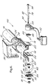
- Figure 1 is an exploded view of a clamping device in accordance with the present invention;
- Figures 2 is a cross-sectional view of the clamping device of Figure 1;
- Figure 3 is a perspective view of the clamping mechanism of the clamping device of Figure 1 in the clamped position;
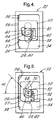
- Figure 4 is a side view of the clamping mechanism of Figure 3 in the clamped position;
- Figure 5 is a side view of the clamping mechanism of Figure 3 in the released position; and
- Figure 6 is an exploded view of a second embodiment of a clamping device in accordance with the present invention.
-
- Referring to Figures 1 to 5 of the drawings, the
clamping device 10 of the present invention is for use with a steering column (not shown) of a motor vehicle. Theclamping device 10 is such as to allow the steering column to rake and/or telescope relative to the vehicle body (not shown) on which the column is mounted. - The
clamping device 10 comprises afirst bracket 12 which, in use, is secured to the vehicle body in any suitable arrangement; and asecond bracket 14 which is secured (in any suitable manner) to a portion of the steering column, typically by way of atubular jacket 16. - The
second bracket 14 includes a pair of spacedarms 18 which are normally positioned on either side of the steering column and are preferably connected by abridge member 20. Eacharm 18 of thesecond bracket 14 has anelongate aperture 22 formed therein which extends in a direction substantially parallel to the axis A of the steering column. Theapertures 22 in eacharm 18 are substantially aligned. - The
first bracket 12 includes a pair of spacedarms 24, each of which is positioned adjacent one of thearms 18 of thesecond bracket 14. Thearms 24 of thefirst bracket 12 are preferably connected by abridge member 26. Eacharm 24 of thefirst bracket 12 has anelongate aperture 28 formed therein which extends in a direction at an angle to, and substantially perpendicular to, theaperture 22 in theadjacent arm 18 of thesecond bracket 14. Theapertures 28 in thearms 24 are substantially aligned. - A
clamping mechanism 30 is used to releasably clamp the first andsecond brackets clamping mechanism 30 comprises atoothed plate 32 which is secured on one of thearms 24 of thefirst bracket 12. Thetoothed plate 32 comprises a substantiallyrectangular aperture 34 havingteeth 36 formed in oneedge 38 of the aperture. Thetoothed plate 32 also has anaperture 40 therethrough which either defines, or aligns with and is substantially identical to, theaperture 28 in thearm 24 on which the toothed plate is mounted. A substantiallyrectangular insert 50 is positioned inside therectangular aperture 34 and is sized to allow movement of the insert relative to thetoothed plate 32 in any direction. Theinsert 50 hasteeth 56 formed in oneedge 57 which correspond with and are engageable with theteeth 36 of thetoothed plate 32. Theinsert 50 also has ashaped aperture 58 within which aneccentric cam 60 is rotatably mounted. Aspring 62 is mounted in theshaped aperture 58 and acts on theeccentric cam 60 to normally bias theteeth 56 on theinsert 50 away from theteeth 36 in thetoothed plate 32. - The
clamping mechanism 30 further comprises alever 42 which can pivot about an axis B which extends through theapertures arms second brackets apertures toothed plate 32; and theaperture 58 in theinsert 50. Thelever 42 is secured to acam 44 which is rotatable about the pivot axis B.A cam follower 46 is positioned next to thecam 44. Thecam follower 46 hasguide pegs 51 which extend into (and slide in) theaperture 28 in theadjacent arm 24, and which substantially prevent rotation of the cam follower about the pivot axis B. Thecam follower 46 has acam surface 48 adjacent acorresponding cam surface 52 on thecam 44. Thecam surfaces - The
clamping mechanism 30 is secured together and in place on thebrackets bolt 78 andnut 80. Thebolt 78 has ashank 82 which extends along the pivot axis B through thecam 44, thecam follower 46, theapertures brackets apertures toothed plate 32, and theaperture 58 in theinsert 50. Thebolt 78 has an enlargedhead 84 at one end of theshank 82, and thenut 80 is threaded on the other end of the shank. Thehead 84 of thebolt 78 engages thelever 42. Theeccentric cam 60 is secured to, and rotates with, theshank 82 of thebolt 78 about the pivot axis B. Thethrust washer 54 is positioned between, and engages, thenut 80 and the toothed plate 32 (or theadjacent arm 24 of thefirst bracket 12 on which the toothed plate is secured) to bias thecam surfaces - In the clamped position of the
clamping mechanism 30, as shown in Figure 2, theadjacent arms second brackets first bracket 12 relative to thesecond bracket 14. Additionally, (as shown in Figures 3 and 4), theteeth 56 on theinsert 50 interengage with theteeth 36 on thetoothed plate 32 to increase the clamping or holding load, with afirst surface 64 of theeccentric cam 60 in engagement with afirst edge 66 of theshaped aperture 58 to lock the teeth together. - In order to move the
clamping mechanism 30 to a released position, thelever 42 is rotated in a first direction about the pivot axis B. Such rotation of thelever 42 rotates thecam surface 52 on thecam 44, about the pivot axis B, relative to thecam surface 48 on thecam follower 46. As thecam surfaces cam 44 moves axially along the pivot axis B towards thenut 80 to release the frictional engagement between theadjacent arms second brackets lever 42 causes theshank 82 of thebolt 78 to rotate about the pivot axis B, thereby causing theeccentric cam 60 to rotate about the pivot axis relative to theinsert 50. The movement of theeccentric cam 60 is such that thefirst surface 64 of the eccentric cam becomes disengaged from thefirst edge 66 of theshaped aperture 58, and asecond surface 68 of the eccentric cam becomes engaged with asecond edge 70 of the shaped aperture. The engagement of thesecond surface 68 with thesecond edge 70 moves theinsert 50 relative to the toothed plate 32 (due to the bias of the spring 62) to disengage theteeth 36, 56 (Figure 5). In the released position of theclamping mechanism 30, thesecond bracket 14 is capable of telescopic and/or rake movement relative to thefirst bracket 12. - In order to move the
clamping mechanism 30 back to the clamping position, thelever 42 is rotated in the opposite direction to the first direction about the pivot axis B. Such action has the reverse effect to that described above during release, and thecam 44 moves away from thenut 80 to bring thearms teeth - In the second embodiment of
clamping device 100 shown in Figure 6, like parts have been given the same reference numeral as in Figures 1 to 5. In the second embodiment, therectangular aperture 34 of thetoothed plate 32 hasteeth 36,36' formed along twoadjacent edges 38,38'. A second insert 50' is positioned in therectangular aperture 34 of thetoothed plate 32 axially adjacent thefirst insert 50. The second insert 50' has a substantially identical shape to thefirst insert 50, with a spring 62' positioned in the shaped aperture 58' of the second insert. The second insert 50' has teeth 56' which are engageable with the teeth 36' of thetoothed plate 32. Theeccentric cam 60 extends into theshaped aperture 58,58' of both thefirst insert 50 and the second insert 50', and acts on the inserts in the same manner, and in the manner described above in respect of Figures 1 to 5. Alternatively, a second eccentric cam may be positioned in the shaped aperture 58' of the second insert 50'. In the clamped position of theclamping mechanism 30, theteeth 56 on thefirst insert 50 engage theteeth 36 of thetoothed plate 32, and the teeth 56' of the second insert 50' engage the teeth 36' of the toothed plate. In the released position of the clampingmember 30, theteeth 56,56'; 36,36' are disengaged. - The present invention provides a clamping device with a clamping mechanism which is simple and easy to assemble, which is capable of providing an increase in clamping force over previously known arrangements, and which can easily be added to current designs having a friction grip between the arms of the brackets. In the arrangement of Figures 1 to 5, the increase in clamping load is either in the telescope direction or in the rake direction dependent on the position of the
teeth second brackets - To reduce the risk of peak-to-peak engagement of the teeth during clamping, the teeth are preferably at an angle α (Figure 5) to the respective edges of the rectangular aperture and the insert, the angle α preferably being substantially the same as the angle through which the eccentric cam rotates between the clamped and released positions. In the above described embodiments, the
toothed plate 32 is separately formed and secured to thearm 24 of thefirst bracket 12, with theaperture 40 in the toothed plate defining theelongate aperture 28 in the arm. Alternatively, the toothed plate may be separately formed and secured on the outer surface of the arm of the first bracket, in which case the elongate aperture in the arm and the aperture in the toothed plate will be separately formed. In a further alternative, thetoothed plate 32 may be integrally formed with thearm 24 of thefirst bracket 12. A similar toothed plate, insert, and eccentric cam may be associated with the other arm of the first bracket, or with one or both arms of the second bracket. The holding clamping force can be altered by changing the profile and/or the dimensions of the teeth on the toothed plate and the teeth on the insert, and/or the profile of the eccentric cam.
Claims (13)
- A clamping device for the steering column of a motor vehicle comprising a first bracket securable to the vehicle, the first bracket having a pair of spaced arms, each arm having an elongate aperture, the apertures being substantially aligned; a second bracket securable to the steering column, the second bracket having a pair of spaced arms, each arm having an elongate aperture, the apertures being substantially aligned; each arm of the first bracket being positioned adjacent one of the arms of the second bracket, with the apertures in the arms of the first bracket being at an angle to the apertures in the arms of the second bracket; and a clamping mechanism including a bolt member having an enlarged head and a threaded shank extending through the apertures in the arms of the first and second brackets; a nut threaded on the shank; a pivotable member having a cam surface mounted on the shank; a cam follower rotatably mounted on the shank and having a cam surface in engagement with the cam surface on the pivotable member, the pivotable member being rotatable relative to the cam follower between a clamped position of the clamping mechanism in which the arms of the bracket frictionally engage, and a release position in which the arms are frictionally disengaged; the clamping mechanism further including a substantially rectangular aperture on one of the arms of one of the brackets aligned with the aperture in the arm; a substantially rectangular insert positioned in the rectangular aperture and having a shaped aperture; and an eccentric cam secured to the shank and positioned in the shaped aperture; the rectangular aperture and the insert having corresponding teeth formed in adjacent edges, the eccentric cam acting on the insert to cause the teeth to interengage in the clamped position and to disengage in the release position.
- A clamping device as claimed in Claim 1, wherein a first surface on the eccentric cam engages a first edge of the shaped aperture in the clamped position and a second surface of the eccentric cam engages a second edge of the shaped aperture in the release position.
- A clamping device as claimed in Claim 1 or Claim 2, wherein a spring is positioned in the shaped aperture and acts on the eccentric cam to normally bias the teeth away from one another.
- A clamping device as claimed in any one of Claims 1 to 3, further comprising a second substantially rectangular insert positioned in the rectangular aperture and having a shaped aperture; and a second eccentric cam secured to the shank and positioned in the shaped aperture of the second insert; the rectangular aperture and the second insert having corresponding teeth formed in adjacent edges, the second eccentric cam acting on the second insert to cause the teeth to interengage in the clamped position and to disengage in the release position.
- A clamping device as claimed in Claim 4, wherein a first surface on the second eccentric cam engages a first edge of the shaped aperture of the second insert in the clamped position and a second surface of the second eccentric cam engages a second edge of the shaped aperture in the second insert in the release position.
- A clamping device as claimed in Claim 4 or Claim 5, wherein a spring is positioned in the shaped aperture of the second insert and acts on the second eccentric cam to normally bias the teeth away from one another.
- A clamping device as claimed in any one of Claims 4 to 6, wherein the first and second eccentric cams are integrally formed in one piece.
- A clamping device as claimed in any one of Claims 1 to 7, wherein the rectangular aperture is formed in a separately formed plate member which is secured to said one of the arms of one of the brackets, the plate member having an aperture corresponding to the elongate aperture in said one arm.
- A clamping device as claimed in Claim 8, wherein the aperture in the plate member defines the elongate aperture in said one of the arms of one of the brackets.
- A clamping device as claimed in any one of Claims 1 to 7, wherein the rectangular aperture is integrally formed in said one of the arms of one of the brackets.
- A clamping device as claimed in any one of Claims 1 to 10, wherein the teeth extend at an angle to the edges in which the teeth are formed.
- A clamping device as claimed in Claim 11, wherein the angle of the teeth is substantially the same as the angle through which the or each eccentric cam rotates between the clamped position and the release position.
- A clamping device as claimed in any one of Claims 1 to 12, wherein the pivotable member comprises a lever and a cam, the cam having the cam surface engaged with the cam follower.
Applications Claiming Priority (2)
| Application Number | Priority Date | Filing Date | Title |
|---|---|---|---|
| GB9916921A GB2352284A (en) | 1999-07-19 | 1999-07-19 | Clamping device for a steering column |
| GB9916921 | 1999-07-19 |
Publications (2)
| Publication Number | Publication Date |
|---|---|
| EP1070652A2 true EP1070652A2 (en) | 2001-01-24 |
| EP1070652A3 EP1070652A3 (en) | 2004-03-24 |
Family
ID=10857522
Family Applications (1)
| Application Number | Title | Priority Date | Filing Date |
|---|---|---|---|
| EP00202250A Withdrawn EP1070652A3 (en) | 1999-07-19 | 2000-06-27 | Clamping device for a steering column |
Country Status (2)
| Country | Link |
|---|---|
| EP (1) | EP1070652A3 (en) |
| GB (1) | GB2352284A (en) |
Cited By (17)
| Publication number | Priority date | Publication date | Assignee | Title |
|---|---|---|---|---|
| EP1110844A1 (en) * | 1999-12-10 | 2001-06-27 | Faurecia Industries | Position locking device for an adjustable steering column, especially for an automotive vehicle, and steering column with such a device |
| EP1445168A1 (en) * | 2003-02-10 | 2004-08-11 | NACAM France S.A. | Vertical locking device for a steering column of an automotive vehicle |
| FR2886605A1 (en) * | 2005-06-02 | 2006-12-08 | Timken Co | STEERING COLUMN LOCKING MODULE AND CORRESPONDING STEERING COLUMN |
| KR20070074948A (en) * | 2006-01-11 | 2007-07-18 | 주식회사 만도 | Steering system having tilt-apparatus equipped with lever |
| EP1857346A3 (en) * | 2006-05-19 | 2008-12-10 | Mando Corporation | Tilt-type steering apparatus equipped with radial fixed gear |
| US7533594B2 (en) | 2006-12-13 | 2009-05-19 | Delphi Technologies, Inc. | Position control apparatus for steering column |
| EP1975036A3 (en) * | 2007-03-30 | 2009-11-25 | Delphi Technologies, Inc. | Lock mechanism for an adjustable steering column assembly |
| US7861615B2 (en) | 2005-04-19 | 2011-01-04 | Gm Global Technology Operations, Inc. | Adjustable steering column assembly |
| US8037782B2 (en) | 2007-10-31 | 2011-10-18 | Fuji Kiko Co., Ltd. | Steering column assembly |
| US8056437B2 (en) | 2005-04-19 | 2011-11-15 | Nexteer (Beijing) Technology Co., Ltd. | Electric steering column lock with single direction actuator travel |
| US8201475B2 (en) | 2005-04-19 | 2012-06-19 | Steering Solutions Ip Holding Corporation | Steering column with rake and telescope adjustment |
| CN103253292A (en) * | 2012-02-15 | 2013-08-21 | 操纵技术Ip控股公司 | Steering column telescope and e/a locking device |
| DE10222070B4 (en) * | 2001-05-23 | 2014-05-28 | Nsk Steering Systems Europe Limited | actuating lever |
| CN113007222A (en) * | 2021-02-22 | 2021-06-22 | 陈明光 | Make things convenient for fixed mounting structure of bearing frame |
| CN114104084A (en) * | 2020-08-28 | 2022-03-01 | 吉林世宝机械制造有限公司 | Device for improving holding power by adjusting angle of automobile steering column |
| CN114104083A (en) * | 2020-08-27 | 2022-03-01 | Zf汽车德国有限公司 | Support unit for fastening a steering column in a vehicle |
| CN117680647A (en) * | 2023-12-13 | 2024-03-12 | 连云港江南精工机械有限公司 | Injection punch stop device and stop method |
Families Citing this family (6)
| Publication number | Priority date | Publication date | Assignee | Title |
|---|---|---|---|---|
| DE102014111606B3 (en) * | 2014-08-14 | 2016-01-21 | Thyssenkrupp Ag | Steering column for a motor vehicle |
| KR101603020B1 (en) | 2014-12-18 | 2016-03-21 | 주식회사 만도 | Steering Column Of Vehicle |
| GB201604976D0 (en) * | 2016-03-23 | 2016-05-04 | Trw Das A S | A steering column assembly |
| GB201604977D0 (en) * | 2016-03-23 | 2016-05-04 | Trw Das A S | A steering column assembly |
| GB201604974D0 (en) * | 2016-03-23 | 2016-05-04 | Trw Das A S | A steering column assembly |
| GB201616323D0 (en) * | 2016-09-26 | 2016-11-09 | Trw Limited | A steering column assembly |
Family Cites Families (4)
| Publication number | Priority date | Publication date | Assignee | Title |
|---|---|---|---|---|
| DE3619125C1 (en) * | 1986-06-06 | 1987-10-22 | Daimler Benz Ag | Receiving device for an adjustable steering column of a motor vehicle |
| GB2240383A (en) * | 1990-01-27 | 1991-07-31 | Ford Motor Co | Adjustable steering column mechanism. |
| US5655413A (en) * | 1994-06-22 | 1997-08-12 | The Torrington Company | Antifriction element for use between relatively sliding components of an adjustable steering column |
| US5722299A (en) * | 1994-06-30 | 1998-03-03 | Fuji Kiko Co., Ltd. | Adjustable steering column assembly for a vehicle |
-
1999
- 1999-07-19 GB GB9916921A patent/GB2352284A/en not_active Withdrawn
-
2000
- 2000-06-27 EP EP00202250A patent/EP1070652A3/en not_active Withdrawn
Non-Patent Citations (1)
| Title |
|---|
| None |
Cited By (20)
| Publication number | Priority date | Publication date | Assignee | Title |
|---|---|---|---|---|
| EP1110844A1 (en) * | 1999-12-10 | 2001-06-27 | Faurecia Industries | Position locking device for an adjustable steering column, especially for an automotive vehicle, and steering column with such a device |
| DE10222070B4 (en) * | 2001-05-23 | 2014-05-28 | Nsk Steering Systems Europe Limited | actuating lever |
| EP1445168A1 (en) * | 2003-02-10 | 2004-08-11 | NACAM France S.A. | Vertical locking device for a steering column of an automotive vehicle |
| FR2850935A1 (en) * | 2003-02-10 | 2004-08-13 | Nacam | VERTICAL BLOCKING DEVICE FOR A STEERING COLUMN OF A MOTOR VEHICLE |
| US8056437B2 (en) | 2005-04-19 | 2011-11-15 | Nexteer (Beijing) Technology Co., Ltd. | Electric steering column lock with single direction actuator travel |
| US8220355B2 (en) | 2005-04-19 | 2012-07-17 | Steering Solutions Ip Holding Corporation | Electric steering column lock with single direction actuator travel |
| US7861615B2 (en) | 2005-04-19 | 2011-01-04 | Gm Global Technology Operations, Inc. | Adjustable steering column assembly |
| US8201475B2 (en) | 2005-04-19 | 2012-06-19 | Steering Solutions Ip Holding Corporation | Steering column with rake and telescope adjustment |
| FR2886605A1 (en) * | 2005-06-02 | 2006-12-08 | Timken Co | STEERING COLUMN LOCKING MODULE AND CORRESPONDING STEERING COLUMN |
| KR20070074948A (en) * | 2006-01-11 | 2007-07-18 | 주식회사 만도 | Steering system having tilt-apparatus equipped with lever |
| EP1857346A3 (en) * | 2006-05-19 | 2008-12-10 | Mando Corporation | Tilt-type steering apparatus equipped with radial fixed gear |
| US7533594B2 (en) | 2006-12-13 | 2009-05-19 | Delphi Technologies, Inc. | Position control apparatus for steering column |
| US8047096B2 (en) | 2007-03-30 | 2011-11-01 | Nexteer (Beijing) Technology Co., Ltd. | Lock mechanism for an adjustable steering column assembly |
| EP1975036A3 (en) * | 2007-03-30 | 2009-11-25 | Delphi Technologies, Inc. | Lock mechanism for an adjustable steering column assembly |
| US8037782B2 (en) | 2007-10-31 | 2011-10-18 | Fuji Kiko Co., Ltd. | Steering column assembly |
| CN103253292A (en) * | 2012-02-15 | 2013-08-21 | 操纵技术Ip控股公司 | Steering column telescope and e/a locking device |
| CN114104083A (en) * | 2020-08-27 | 2022-03-01 | Zf汽车德国有限公司 | Support unit for fastening a steering column in a vehicle |
| CN114104084A (en) * | 2020-08-28 | 2022-03-01 | 吉林世宝机械制造有限公司 | Device for improving holding power by adjusting angle of automobile steering column |
| CN113007222A (en) * | 2021-02-22 | 2021-06-22 | 陈明光 | Make things convenient for fixed mounting structure of bearing frame |
| CN117680647A (en) * | 2023-12-13 | 2024-03-12 | 连云港江南精工机械有限公司 | Injection punch stop device and stop method |
Also Published As
| Publication number | Publication date |
|---|---|
| EP1070652A3 (en) | 2004-03-24 |
| GB2352284A (en) | 2001-01-24 |
| GB9916921D0 (en) | 1999-09-22 |
Similar Documents
| Publication | Publication Date | Title |
|---|---|---|
| EP1070652A2 (en) | Clamping device for a steering column | |
| KR101520818B1 (en) | Clamp assembly for a steering column assembly | |
| US8006587B2 (en) | Adjustable steering column for a motor vehicle | |
| US6375257B1 (en) | Chair tablet arm apparatus | |
| US5213003A (en) | Locking device for an adjustable steering column assembly | |
| US7815220B2 (en) | Tilting and telescoping steering column assembly | |
| EP1442940A1 (en) | Rail Bar roof rack | |
| WO2001042706A1 (en) | Improved tripod, in particular for optical and photographic use | |
| US7914043B2 (en) | Adjustable steering column assembly for a vehicle | |
| US5884887A (en) | Lock for slide adjustment of boat seat or table top | |
| US7798037B2 (en) | Wedge arm positive rake lock | |
| GB2352286A (en) | Clamping device for a steering column | |
| EP1995149A2 (en) | Tilt steering apparatus | |
| US20070295144A1 (en) | Steering device | |
| GB2465179A (en) | Clamping device for an adjustable vehicle steering column | |
| IE910105A1 (en) | Clamping device | |
| GB2352285A (en) | Clamping device for a steering column | |
| NL1028758C2 (en) | Assembly provided with a bicycle lock. | |
| US6959622B2 (en) | Rotary tilt locking mechanism | |
| FR2850935A1 (en) | VERTICAL BLOCKING DEVICE FOR A STEERING COLUMN OF A MOTOR VEHICLE | |
| EP0881137B1 (en) | Clamping device. | |
| JPH04110671U (en) | Fixed adjustment structure of telescopic steering | |
| JPS6325265Y2 (en) | ||
| JP2006327355A (en) | Steering device | |
| EP1020326A2 (en) | Clamp for mounting rear view mirrors |
Legal Events
| Date | Code | Title | Description |
|---|---|---|---|
| PUAI | Public reference made under article 153(3) epc to a published international application that has entered the european phase |
Free format text: ORIGINAL CODE: 0009012 |
|
| AK | Designated contracting states |
Kind code of ref document: A2 Designated state(s): AT BE CH CY DE DK ES FI FR GB GR IE IT LI LU MC NL PT SE |
|
| AX | Request for extension of the european patent |
Free format text: AL;LT;LV;MK;RO;SI |
|
| PUAL | Search report despatched |
Free format text: ORIGINAL CODE: 0009013 |
|
| AK | Designated contracting states |
Kind code of ref document: A3 Designated state(s): AT BE CH CY DE DK ES FI FR GB GR IE IT LI LU MC NL PT SE |
|
| AX | Request for extension of the european patent |
Extension state: AL LT LV MK RO SI |
|
| STAA | Information on the status of an ep patent application or granted ep patent |
Free format text: STATUS: THE APPLICATION IS DEEMED TO BE WITHDRAWN |
|
| 18D | Application deemed to be withdrawn |
Effective date: 20040103 |