EP1070533B1 - Method for manufacturing filter having ceramic porous film as separating film - Google Patents
Method for manufacturing filter having ceramic porous film as separating film Download PDFInfo
- Publication number
- EP1070533B1 EP1070533B1 EP00902024A EP00902024A EP1070533B1 EP 1070533 B1 EP1070533 B1 EP 1070533B1 EP 00902024 A EP00902024 A EP 00902024A EP 00902024 A EP00902024 A EP 00902024A EP 1070533 B1 EP1070533 B1 EP 1070533B1
- Authority
- EP
- European Patent Office
- Prior art keywords
- film
- slurry
- deposition
- substrate
- porous substrate
- Prior art date
- Legal status (The legal status is an assumption and is not a legal conclusion. Google has not performed a legal analysis and makes no representation as to the accuracy of the status listed.)
- Expired - Lifetime
Links
Images


Classifications
-
- B—PERFORMING OPERATIONS; TRANSPORTING
- B01—PHYSICAL OR CHEMICAL PROCESSES OR APPARATUS IN GENERAL
- B01D—SEPARATION
- B01D67/00—Processes specially adapted for manufacturing semi-permeable membranes for separation processes or apparatus
- B01D67/0039—Inorganic membrane manufacture
- B01D67/0046—Inorganic membrane manufacture by slurry techniques, e.g. die or slip-casting
-
- B—PERFORMING OPERATIONS; TRANSPORTING
- B01—PHYSICAL OR CHEMICAL PROCESSES OR APPARATUS IN GENERAL
- B01D—SEPARATION
- B01D67/00—Processes specially adapted for manufacturing semi-permeable membranes for separation processes or apparatus
- B01D67/0002—Organic membrane manufacture
- B01D67/0004—Organic membrane manufacture by agglomeration of particles
- B01D67/00046—Organic membrane manufacture by agglomeration of particles by deposition by filtration through a support or base layer
-
- B—PERFORMING OPERATIONS; TRANSPORTING
- B01—PHYSICAL OR CHEMICAL PROCESSES OR APPARATUS IN GENERAL
- B01D—SEPARATION
- B01D69/00—Semi-permeable membranes for separation processes or apparatus characterised by their form, structure or properties; Manufacturing processes specially adapted therefor
- B01D69/10—Supported membranes; Membrane supports
- B01D69/105—Support pretreatment
-
- B—PERFORMING OPERATIONS; TRANSPORTING
- B01—PHYSICAL OR CHEMICAL PROCESSES OR APPARATUS IN GENERAL
- B01D—SEPARATION
- B01D69/00—Semi-permeable membranes for separation processes or apparatus characterised by their form, structure or properties; Manufacturing processes specially adapted therefor
- B01D69/10—Supported membranes; Membrane supports
- B01D69/108—Inorganic support material
-
- B—PERFORMING OPERATIONS; TRANSPORTING
- B01—PHYSICAL OR CHEMICAL PROCESSES OR APPARATUS IN GENERAL
- B01D—SEPARATION
- B01D71/00—Semi-permeable membranes for separation processes or apparatus characterised by the material; Manufacturing processes specially adapted therefor
- B01D71/02—Inorganic material
- B01D71/024—Oxides
-
- C—CHEMISTRY; METALLURGY
- C04—CEMENTS; CONCRETE; ARTIFICIAL STONE; CERAMICS; REFRACTORIES
- C04B—LIME, MAGNESIA; SLAG; CEMENTS; COMPOSITIONS THEREOF, e.g. MORTARS, CONCRETE OR LIKE BUILDING MATERIALS; ARTIFICIAL STONE; CERAMICS; REFRACTORIES; TREATMENT OF NATURAL STONE
- C04B41/00—After-treatment of mortars, concrete, artificial stone or ceramics; Treatment of natural stone
- C04B41/45—Coating or impregnating, e.g. injection in masonry, partial coating of green or fired ceramics, organic coating compositions for adhering together two concrete elements
- C04B41/4582—Porous coatings, e.g. coating containing porous fillers
-
- C—CHEMISTRY; METALLURGY
- C04—CEMENTS; CONCRETE; ARTIFICIAL STONE; CERAMICS; REFRACTORIES
- C04B—LIME, MAGNESIA; SLAG; CEMENTS; COMPOSITIONS THEREOF, e.g. MORTARS, CONCRETE OR LIKE BUILDING MATERIALS; ARTIFICIAL STONE; CERAMICS; REFRACTORIES; TREATMENT OF NATURAL STONE
- C04B41/00—After-treatment of mortars, concrete, artificial stone or ceramics; Treatment of natural stone
- C04B41/80—After-treatment of mortars, concrete, artificial stone or ceramics; Treatment of natural stone of only ceramics
- C04B41/81—Coating or impregnation
-
- B—PERFORMING OPERATIONS; TRANSPORTING
- B01—PHYSICAL OR CHEMICAL PROCESSES OR APPARATUS IN GENERAL
- B01D—SEPARATION
- B01D2325/00—Details relating to properties of membranes
- B01D2325/04—Characteristic thickness
-
- C—CHEMISTRY; METALLURGY
- C04—CEMENTS; CONCRETE; ARTIFICIAL STONE; CERAMICS; REFRACTORIES
- C04B—LIME, MAGNESIA; SLAG; CEMENTS; COMPOSITIONS THEREOF, e.g. MORTARS, CONCRETE OR LIKE BUILDING MATERIALS; ARTIFICIAL STONE; CERAMICS; REFRACTORIES; TREATMENT OF NATURAL STONE
- C04B2111/00—Mortars, concrete or artificial stone or mixtures to prepare them, characterised by specific function, property or use
- C04B2111/00474—Uses not provided for elsewhere in C04B2111/00
- C04B2111/00793—Uses not provided for elsewhere in C04B2111/00 as filters or diaphragms
Definitions
- the Present invention relates to a method for manufacturing a filter utilizing a ceramic porous membrane (referred as a porous membrane hereinafter) as a separation film.
- the present invention particularly relates to a method for manufacturing a filter having a uniform film thickness and smooth film face, as well as being able to form a porous membrane with a sharp micro-pore size distribution.
- Filters utilizing a ceramic porous membrane as a separation film is useful as solid-liquid separation filters as compared with the filters utilizing a polymer membrane as a separation film, since the ceramic filter is highly reliable due to its excellent physical strength and durability and has high corrosion resistance to hardly cause degradation by cleaning with an acid or alkali, in addition to an advantages that its micro-pore size that determines filtration ability is precisely controllable.
- the separation filter that has been frequently used comprises a ceramic porous membrane formed on a porous substrate, wherein the ceramic porous membrane has a far more finer pore size than the porous substrate for improving filtration performance while maintaining a given level of water permeation rate.
- the filter described above may be manufactured by allowing a slurry containing framework particles to deposit to form a film by a conventional slurry deposition method, for example a dipping method, followed by firing the deposited film
- a conventional slurry deposition method for example a dipping method
- the inventors of the present invention have disclosed an excellent slurry deposition method - a filtration deposition method - by which film defects such as pin holes can be prevented from being generated (Japanese Examined Patent Application Publication No. 63-66566).
- the face to be provided with a separation film is isolated to be airtight from the face not provided with the separation film, after substituting the fine pores inside of the porous substrate with a liquid. Then, a film deposition slurry containing ceramic framework particles is allowed to contact the face to be provided with the separation film by continuously feeding the slurry, and a filtration differential filtration pressure is applied between the face to be provided with the separation film and the face not provided with the separation film, thereby depositing a slurry film on the surface of the porous substrate.
- a slurry is deposited on an inner wall of a through-hole of a porous substrate prepared by forming a single through-hole along the longitudinal direction of a cylinder (referred as a tubular substrate hereinafter).
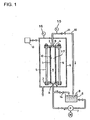
- a tubular substrate As shown in Fig. 1, the inside and the outer circumference side of the through-hole of the porous substrate 1 whose fine pores are substituted with a liquid is secured with flanges 2 and 3 , and bolts 5 in an apparatus comprising a vacuum chamber 6 , a reservoir 8 , a pump 7 , the flanges 2 and 3 , and a tubing 10 , so that one side is isolated from the other side to be airtight.
- the inside of the vacuum chamber 6 is evacuated with a vacuum pump 13 so that the pressure at the outer circumference side of the porous substrate 1 is reduced, while allowing a slurry 9 in the reservoir 8 to contact the inner wall 12 of the through-hole by continuously feeding the slurry into the through-hole of the porous substrate 1 .
- a slurry film is deposited on the inner wall 12 of the through-hole of the porous substrate 1 by the operation as described above, because a differential filtration pressure is applied between the outer circumference side of the porous substrate 1 and the inner wall 12 of the through-hole, and water in the slurry is discharged as a filtrate from the outer circumference side of the porous substrate 1 .
- Film defects such as pin-holes may be prevented from generating in the filtration deposition method as described above since a pre-treatment for substituting the remaining air in the fine-pores of the porous substrate 1 is applied.
- Continuously feeding the slurry into the through-hole permits a deposition film having a uniform thickness and quality to be formed because framework particles in the slurry are slowly deposited. Accordingly, a filter with better quality may be obtained as compared with a filter obtained by a film deposition method such as a dipping method.
- the advantage of the filtration deposition method that a film with a uniform thickness and quality can be formed is apt to be offset due to the recent tendency to make the filtration area, or the filter size itself, large for the purpose of improving the filtration ability of the filter.
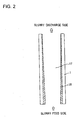
- the film deposition is more easily proceeded at the slurry feed side than at the slurry discharge side where the film deposition is hardly proceeded as shown in Fig. 2, thereby it was difficult to deposit the slurry in the through-hole with a uniform film thickness.
- the filtration deposition method When the filtration deposition method is applied to the porous substrate having a plurality of the through-holes formed in parallel relation to one another along the longitudinal direction of the cylinder (referred as a revolver magazine type substrate hereinafter), film deposition is facilitated in the through-holes located at the outer circumference side of the plural through-holes of the porous substrate as shown in Fig. 3 and, on the contrary, the films are hardly deposited in the through-holes located at near the center of the porous substrate. Consequently, it is difficult to form slurry deposition films with a uniform film thickness in all the through-holes, besides the slurry deposition film is formed with larger thickness at the outer circumference side of the porous substrate even in one through-hole.
- the second problem may be partly solved by increasing the thickness of the slurry deposition film, the film thickness in all the through-holes cannot be made uniform by any means.
- this method is not preferable since the porous membrane formed after firing has a large film thickness to result in lowering of the water permeation rate (or filtration ability) of the filter.
- a third problem is that the surface of the porous membrane is roughened as shown in Fig. 4 irrespective of the configuration of the substrate, or the micro-pore size distribution of the porous membrane turns out to be broad.
- JP-A-2-90927 illustrates the apparatus of Fig. 1 described above and includes examples of forming a porous thin membrane on an alumina substrate in which an acrylic resin binder or a carboxymethyl cellulose is included in a coating material in the form of a water suspension of alumina powder.
- the present invention provides a method for manufacturing a filter having a ceramic porous membrane as a separation film, as set out in claim 1.
- the substrate is a cylindrical porous substrate containing a single or a plurality of through-holes formed along the longitudinal direction of the cylinder
- the method comprises the steps of isolating the inner side of the through-holes of the porous substrate to be airtight from the outer circumference side of the porous substrate, continuously feeding the film deposition slurry into the through-holes to allow the slurry to contact the inner walls of the through-holes, applying a differential filtration pressure between the inner side of the through-holes of the porous substrate and the outer circumference side of the porous substrate, and depositing the slurry on the inner walls of the through-holes of the porous substrate.
- an organic polymer for endowing the deposition film layer with filtration resistance is added into the slurry in the filtration film deposition step for allowing the slurry to deposit on the porous substrate as a film.
- porous membrane having a uniform film thickness and smooth film surface as well as a sharp micro-pore size distribution.
- fine (or micro) pore size and “particles size” as used herein refers to “mean fine (or micro) pore size” and “mean particles size”, respectively.
- the porous substrate refers to a porous body having a number of fine pores with a relatively large pore size of 0.05 to 50 ⁇ m, and a porous membrane having a more finer micro-pore size may be formed on the porous body.
- the material of the substrate is not particularly restricted so long as the substrate comprises a porous material, and either a ceramic or a metal may be available.
- ceramics are preferable in view of durability, and alumina, titania, mullite, zirconia and a mixture thereof may be advantageously used.
- the configuration of the substrate is not particularly restricted in the present invention, and the substrate may be a plate.
- the method of the present invention may be particularly advantageous when the film is formed by deposition of a slurry on the inner wall of a tubular substrate having a length of 50 cm or more, or on the inner walls of the through-holes of a revolver magazine type substrate.
- the slurry for depositing a film according to the present invention refers to a slurry for forming a ceramic porous membrane as a separation film by firing on the surface of the substrate, and contains framework particles comprising a ceramic.
- the framework particles as used in the present invention refers to the particles that form a framework of the porous membrane, and the micro-pore size of the porous membrane, or the function of the filter, is determined by the particle size of the framework particles.
- a porous membrane having a desired micro-pore size may be obtained by appropriately selecting the particle size of the framework particles.
- the framework particles having a relatively small particles size of 0.1 to 10 ⁇ m are used herein since the object of the present invention is to form a porous membrane having a micro-pore size of 0.05 to 1 ⁇ m.
- the kind of the framework particles is not particularly restricted so long as the particles comprise a ceramic such as, for example, alumina, titania, mullite, zirconia silica, spinel or a mixture thereof.
- the preferable concentration of the framework particles in the slurry is usually adjusted to 0.5 to 40% by weight, although it depends on the thickness of the deposition film.
- concentration is less than 0.5% by weight, film deposition will take a long period of time while, when the concentration exceeds 40% by weight, the framework particles are aggregated to be liable to generate defects on the porous membrane.
- a dispersing agent for improving dispersion property, a crack preventing agent for preventing cracks from generating in the dried deposition film and other additives may be purposely added.
- the slurry for depositing a film according to the present invention may contain binders such as a ceramic or a compound that is converted into a ceramic by heat treatment (such a slurry is referred as a low temperature firing slurry hereinafter).
- binders such as a ceramic or a compound that is converted into a ceramic by heat treatment (such a slurry is referred as a low temperature firing slurry hereinafter).
- the binder as described above permits a high strength porous membrane to be formed even by firing at a temperature of 300 to 700° C where the framework particles do not form a neck among them, because the binder forms tight bonds among the fine particles or among the fine particles and the framework particles by firing.
- the fine particles as used in the present invention refers to the ceramic particles having a particle size of within a range of 5 to 100 nm, examples of them including ceramic sol particles and ceramic fine powder particles (referred as sol particles and fine powder particles, respectively, hereinafter).
- sol particles and fine powder particles respectively, hereinafter.
- a compound that is converted into a ceramic by heat treatment includes, for example, zirconium oxychloride and titanium tetrachloride.
- the precursor can exert the same effect as the ceramic fine particles do, because it is oxidized by firing at 300 to 700°C in the air and is converted into a ceramic.
- the kind of the ceramic derived from the binder is not particularly restricted, it is preferable to use a composition containing 50% by weight or more of titania or zirconia as a principal component from the point of improving corrosion resistance of binding portions, which are liable to be corroded as compared with the framework particles. A far more higher alkali resistance may be secured by using a composition containing 80% by weight or more of the principal component.
- sol particles and the fine particles may be prepared in the laboratory, a commercially available sol solution with a solid fraction concentration of 5 to 40%, for example a hydrolysate of titanium isopropoxide TR-20A (trade name; made by Nissan Chemical Industries, Co.), and a fine powder particles Nano Tek TiO 2 (trade name; made by C.I. Chemicals, Co.) may be used.
- a hydrolysate of titanium isopropoxide TR-20A trade name; made by Nissan Chemical Industries, Co.
- Nano Tek TiO 2 trade name; made by C.I. Chemicals, Co.
- the slurry for film deposition as described above is deposited on the surface of the substrate by the filtration deposition method in the manufacturing method according to the present invention.
- a pre-treatment for allowing the air in the fine pores of the porous substrate to be substituted with a liquid is at first applied in the deposition step of the filtration deposition method, because the remaining air in the fine pores causes film defects such as pin holes during film deposition.
- the substrate While the substrate may be allowed to vibrate by immersing it in a liquid for removing the remaining air, it is more securely removed by immersing the substrate in a liquid followed by heating (boiling) or evacuating the liquid.
- Water is a preferable liquid for substituting with the air, since water is used for the solvent of the slurry and is easy in handling.
- the slurry for film deposition is continuously fed to allow it to contact the face to be provided with the separation film, after isolating the face to be provided with the separation film to be airtight from the face not provided with the separation film.
- Continuously feeding the slurry permits deposition of the film with a uniform thickness without heterogeneous deposition of the framework particles in the slurry.
- the face to be provided with the separation film and “the face not provided with the separation film” refer to the top face and bottom face in a plate type substrate, respectively, or the inner wall of the through-hole and outer circumference face of the substrate, respectively, of a tubular or a revolver magazine type substrate, although the definition depends on the configuration of the substrate.
- a differential pressure is applied between the side to be provided with the separation film and the side not provided with the separation film in the present invention, while the slurry is continuously fed on the face to be provided with the separation film.
- the pressure at the side not provided with the separation film is reduced, and/or the pressure at the side provided with the separation film is increased.
- Applying a differential filtration pressure allows the liquid filled within the fine pores of the substrate to be discharged from the side not provided with the separation film, while depositing a slurry film on the face to be provided with the separation film on the substrate.
- the membrane is finally dehydrated while keeping the reduced pressure after discharging the remaining slurry by stopping feed of the slurry.
- the dehydration time is about 1 minutes to 1 hour, although it differs depending on the nature of the slurry.
- the conventional filtration deposition method involved the problems that (1) the film is more readily deposited at the slurry feed side terminal and hardly deposited at the slurry discharge side terminal, when the film is deposited on the inner wall of a long size through-hole (Fig. 5), (2) the film is more readily deposited in the through holes at the outer circumference side and hardly deposited in the through-holes at near the center of the substrate, when the film is deposited on the inner wall of the through-holes of the revolver magazine type substrate (Fig. 6), and (3) a porous membrane with a good quality cannot be sometimes obtained because the surface of the porous membrane formed turns out to be rough (Fig. 7), and the porous membrane has a broad micro-pore size distribution.
- the inventors of the present invention have studied the phenomena described above in detail, and found that the phenomena were caused by differential filtration pressures being different at respective sites on the substrate during deposition of the filtration membrane, thereby forming a deposition film having varying thickness throughout the film.
- film deposition is ready to proceed in the through-holes in the vicinity of the evacuated outer circumference side of the substrate due to small pressure loss and large differential pressure.
- film deposition hardly proceeds in the through-holes at near the center of the substrate since pressure loss is large and differential pressure is small.
- Other phenomena described above is conjectured to be caused by similar reasons.
- filtration resistant agent An organic polymer for endowing the film deposition layer with filtration resistance (referred as "filtration resistant agent” hereinafter) is added to the film deposition slurry in the manufacturing method according to the present invention.
- the resistance for allowing a solvent to permeate through the film deposition layer is considerably increased as compared with the resistance in the substrate by endowing the deposition film layer with a filtration resistance. Accordingly, more uniform differential filtration pressure is applied over the entire surface of the substrate to be provided with the separation film, irrespective of the difference of the pressure loss in the substrate.
- the filtration resistant agent is able to endow the deposition film layer with a filtration resistance during deposition of slurry film.
- the agent should be a material that does not plug the micro-pores of the porous membrane and fine pores of the substrate after forming the porous membrane by firing, or the agent should be an organic polymer.
- Long-chain molecules like organic polymers are preferable in that they are ready to stay within the substrate and the deposition film layer to further increase the filtration resistance.
- filtration resistant agent used in the invention is selected from the natural polymers gelatin, starch, chitosan, welan gum, agar and a mixture thereof.
- Welan gum and agar are preferable in that a minute quantity of addition makes the filtration resistance large, because they act as if they were a larger molecules by forming molecular networks.
- Welan gum is a kind of natural polysaccharide having repeating units comprising either (1) two molecules of glucose, two molecules of rhamnose and one molecules of glucuronic acid, or (2) two molecules of glucose, one molecules of rhamnose, one molecule of mannose and one molecule of glucuronic acid.
- mixture refers to a mixture containing 1% by weight or more of agar or welan gum. While the substances to be mixed with welan gum and agar are not particularly restricted, saccharides such as monosaccharides (for example glucose) and oligosaccharide as well as other polymers such as polyvinyl alcohol, acrylic resins and polyethylene glycol may be used.
- saccharides such as monosaccharides (for example glucose) and oligosaccharide as well as other polymers such as polyvinyl alcohol, acrylic resins and polyethylene glycol may be used.
- the filtration resistant agent should be chemically stable under an acidic condition besides satisfying the conditions as described above when the slurry for film deposition is used for firing at a low temperature, because the slurry fired at a low temperature is strongly acidic having a pH vale of 2 or below.
- the slurry should be maintained in an acidic solution in order to permit the sol particles to be securely dispersed, when the binder comprises ceramic sol particles.
- the filtration resistant agent should not inhibit the function of the binder, because adding the filtration resistant agent may sometimes weaken the strength of the porous membrane formed depending on the kind of the filtration resistant agent.
- filtration resistant agents examples include welan gum, agar and mixtures thereof. These filtration resistant agents are preferably used in a wide composition range of the slurry. Welan gum is particularly preferable among them since it has a high acid resistance and persists in the slurry for a long period of time.
- the filtration resistant agent may be an acrylic resin when the binder is titania sol particles.
- the method for preparing the slurry is of problem in this case because, for example, the titania sol particles and the acrylic resin form a network to generate irreversibly aggregated particles, when the acrylic resin is added all at once after preparing a slurry containing the framework particles and the titania sol particles.
- a film deposition slurry is prepared in the case described above by adding the acrylic resin dropwise into an aqueous solution of the titania sol particles with mixing, followed by adding the slurry containing the framework particles dropwise into the mixed solution obtained with mixing.
- the preparation method as described above permits a film deposition slurry to be prepared without forming irreversibly aggregated particles as a result of a network between the titania sol and the acrylic resin.
- the manufacturing method according to the present invention it is possible in the manufacturing method according to the present invention to control the thickness of the slurry deposition film by the weight ratio between the framework particles and the filtration resistant agent, or by the ratio between the slurry feed rate and the differential filtration pressure. This is due to the presence of a film thickness that cannot be increased beyond it (this film thickness is referred as a "critical thickness” hereinafter), or because the critical thickness is controllable by the foregoing factors, even when the filtration film deposition step is continued for depositing the slurry supplemented with the filtration resistant agent by the filtration deposition method.
- the pressure loss in the deposition film layer is increased when the deposition film is thickened after proceeding film deposition of the slurry to a given degree, thereby gradually weakening the force for attracting the framework particles in the slurry fed into the through-hole onto the side of the face for depositing the film.
- a force for scratching the surface of the deposition film layer off ascribed to the shear force of the continuously fed slurry is constant on the deposition film face. Accordingly, the film thickness turns out to be constant when the force for attracting the framework particles onto the film deposition face side is in equilibrium with the force for scratching the surface of the deposition film layer, inhibiting additional growth of the deposition film.
- the larger ratio, or the smaller ratio, between the differential filtration pressure and the slurry feed rate makes the critical film thickness larger or smaller, respectively, when the slurry composition is fixed.
- the "slurry feed rate" as used in the present invention actually refers to the rate for allowing the slurry to travel on the deposition film face (the rate is referred as a "linear film surface velocity"), and does not mean the feed rate of the pump.
- the force for scratching the surface of the deposition film is actually determined by the rate for allowing the slurry to travel on the deposition film face, the force for scratching the surface of the deposition film increases by reducing the diameter of the through-hole of the substrate, even when the discharge rate of the pump is constant.
- the critical film thickness is conjectured to be affected by the magnitude of the filtration resistance applied on the deposition film layer, because large filtration resistance weakens the force for attracting the framework particles in the slurry onto the film deposition face side. Accordingly, the critical film thickness is controllable by the weight ratio between the framework particles in the slurry and the filtration resistant agent that determined the filtration resistance. In other words, the critical film thickness is increased as the weight ratio between the framework particles and the filtration resistant agent is increased and, on the contrary, the critical film thickness is reduced as the weight ratio between the framework particles and the filtration resistant agent is reduced, when the film deposition conditions such as the differential filtration pressure and the slurry feed rate are kept constant.
- a filter having a porous membrane with a desired thickness can be manufactured by appropriately setting the slurry deposition conditions and slurry compositions, in addition to making the film thickness uniform, in the manufacturing method according to the present invention.
- the manufacturing method described above is able to make the porous membrane thin while keeping uniformity of the film thickness, it is quite useful for easily manufacturing a filter having a large water permeation rate (or a high treatment performance) while maintaining its filtration ability.
- the slurry is deposited up to the critical film thickness in the through-holes at near the center or at the discharge side terminal of the song-size substrate or the revolver magazine type substrate by applying the method that is able to securely make the film thickness uniform, although these sites have been hardly endowed with the filtration resistance.
- the substrate on the surface of which the slurry containing the framework particles has been deposited (referred as a film deposition substrate hereinafter) is obtained by the method as hitherto described, and the filter comprising a porous membrane with a film thickness of about 1 to 300 ⁇ m and micro-pore size of about 0.05 to 1 ⁇ m on the surface of the film deposition substrate is manufactured by the method for firing the film deposition substrate at a temperature of as high as about 1400°C (referred as a high temperature firing method hereinafter).
- the film deposition substrate on which the low temperature firing slurry containing the binder has been deposited may be fired at a temperature of 300 to 700°C in the air (referred as a low temperature firing method hereinafter).
- a low temperature firing method When the firing temperature is lower than 300°C, a tough bond portions cannot be formed among the framework particles. Although bonding among the framework particles becomes more tough when the firing temperature is higher than 700°C, on the other hand, a large amount of energy is required in addition to a fireproo1f facilities, resulting in an increased manufacturing cost.
- a tunnel furnace that is suitable for mass-production is preferably used for the heat treatment.
- porous substrate The porous substrate, film deposition slurry, the film deposition method and the firing method will be described below.
- a substrate Three kinds of the porous substrates (referred as a substrate hereinafter) as described below were appropriately selected for use. All the substrates were subjected to a pre-treatment by which the air in the fine-pores of the substrate was substituted with water by immersing the substrate in water for more than three hours under a reduced pressure of 0.1 atm or below.
- the film deposition slurry (referred as a slurry hereinafter) was deposited on the substrate after a vacuum degassing treatment for removing air bubbles in the slurry.
- the filtration membrane was prepared by a filtration deposition method using an apparatus comprising a vacuum chamber 6 , a reservoir 8 , a slurry pump 7 , flanges 2 and 3 , and a tubing 10 as shown in Fig. 4.
- the slurry 9 in the reservoir 8 was continuously fed into the through-hole 17 for 30 minutes with the slurry pump 7 at a feed pressure of 2 kg/cm 2 .
- the slurry 9 that has not been deposited on the substrate 1 but passing through the through-hole 17 is recycled to the reservoir 8 through the tubing 10 .
- the slurry in the through-hole 17 was deposited by sucking it from the outer circumference side of the substrate 1 , wherein a differential filtration pressure was applied between the outer circumference side of the substrate 1 and the inside of the through-hole 17 by evacuating the inside of the vacuum chamber 6 at a reduced pressure of 0.1 atm or below while continuously feeding the slurry 9 .
- the differential filtration pressure in this case corresponds to the differential pressure between the pressure of the slurry 9 in the through-hole 17 indicated by a pressure gauge 15 and the atmospheric pressure in the vacuum chamber 6 indicated by a pressure gauge 16 .
- the excess slurry in the through-hole 17 was discharged, and the micro-pores of the deposition film layer and the fine pores of the substrate were dehydrated under a reduced pressure by continuously evacuating at a reduced pressure of 0.1 atm or below, followed by drying at 110°C to form a film deposition substrate.
- Firing was performed in all examples using an electric furnace for use in the air.
- Aron AS-7503 (trade name) is an aqua-sol type acrylic resin comprising a W/W type emulsion formed by a graft-polymerization of an acrylic monomer in an aqueous solution of a water-soluble polymer such as polyethylene glycol.
- the agar preparation refers to a mixture comprising 60% by weight of agar with a balance of glucose
- the welan gum/PVA refers to a mixture comprising 10% by weight of welan gum and 90% by weight of polyvinyl alcohol
- the agar/acrylic refers to a mixture comprising 37% by weight of agar and 63% by weight of Aron AS-7503 (trade name).
- Example 1 The effect of making the film thickness uniform using the filtration resistant agent was tested in Example 1.
- the film deposition slurry listed in Table 1 was prepared by adding the framework particles into an aqueous solution of the filtration resistant agent with mixing. The concentration of the framework particles in the slurry was 17% by weight.
- the substrate A was used in this example.
- the film was deposited at a linear film surface velocity of 0.13 ml/sec with a differential filtration pressure of 1 kgf/cm 2 .
- the firing temperature was 1400°C and the firing time was one hour.
- Uniformity of the film thickness was assessed from the mean values and standard deviation of the measured values obtained from 10 sites each of the film, wherein cross sections of the porous membrane at both terminal portions along the longitudinal direction, and at near the center of the filter were photographed under a scanning type electron microscope.
- Example 2 The effects of the composition of the slurry for film deposition, and of the film deposition conditions for controlling the film thickness were investigated in Example 2.
- the slurry for film deposition was prepared by adding the framework particles into an aqueous solution of the filtration resistive agent with mixing.
- the slurry was deposited on the substrate A under the film deposition conditions listed in Table 2, and the deposition film was converted into a filter by firing at 1400°C for 1 hour. Uniformity of the membrane was assessed by the same method as in Example 1. The results are shown in TABLE 2.
- Examples 2-1 and 2-3 to 2-6 the effects for controlling the film thickness was investigated by changing the composition of the slurry for film deposition, while the film deposition conditions were fixed. The results showed the film thickness could be controlled by the critical film thickness varying depending on the weight ratio between the framework particles and the filtration resistive agent (referred as frame/resistive agent ratio hereinafter).
- the thickness of the porous membrane formed under the conditions of the frame/resistive agent ratio of within a range of 20 to 200 showed a standard deviation of within 20%, resulting in a uniform film thickness.
- the smaller frame/resistive agent ratio (or a larger amount of addition of the filtration resistive agent) showed an effect for improving uniformity of the film thickness, even when the frame/resistive agent ratio is within the range of 20 to 200.
- the frame/resistive agent ratio is large (or a smaller amount of the filtration resistive agent is added) even in the presence of the filtration resistive agent as shown in Comparative Example 2-2, on the other hand, the effect for making the film thickness uniform could not be obtained.
- welan gum was used in Examples 2-1, and 2-3 to 2-6 as the filtration resistive agent, it was also possible to control the film thickness, or to make the film thickness uniform, by changing the frame/resistive agent ratio using the agar preparation (Examples 2-14 to 2-16).
- the standard deviation of the film thickness of the porous membrane formed within the differential filtration pressure/linear film surface velocity ratio of 3.76 to 15.4 was within 20%, enabling the film thickness to be uniform.
- the differential filtration pressure/linear film surface velocity ratio can be controlled by merely changing the differential filtration pressure as in Examples 2-7 and 2-8, by merely changing the linear film surface velocity as in Examples 2-9 and 2-1, or by changing both of the differential filtration pressure and the linear film surface velocity.
- the critical film thickness is solely controllable by changing either the frame/resistive agent ratio or the differential filtration pressure/linear film surface velocity ratio, or both of them. Accordingly, the critical film thickness could not be controlled by changing the concentration of the framework particles in the slurry (Examples 2-11 and 2-12) and the particle size of the framework particles (Example 2-13), so long as the frame/resistive agent ratio and the differential filtration pressure/linear film surface velocity ratio are constant.
- Depositing the film up to the critical thickness was not necessarily required for effecting the film thickness be to be uniform as shown in Example 2-2.
- the film thickness was uniform when the film had a thickness of 50% or more of the critical thickness as shown in Example 2-2.
- the film thickness could not be made to be uniform when the film had a thickness of less than 50% of the critical thickness as shown in Example 2-1.
- the filtration resistive agent that is able to use in the low sintering temperature slurry containing the binder was screened in Example 3.
- the slurries for film deposition listed in Table 3 were prepared by adding zirconium oxychloride as a binder and framework particles into an aqueous solution of the filtration resistive agent.
- the concentration of the framework particles in the slurry was 175 by weight, and the substrate A described above was used.
- the firing temperature was 550°C and the firing time was 4 hours.
- Stability of the slurry was judged to be good when the framework particles did not aggregate, and the membrane was deposited on the substrate without leaving any portions having no deposition layers, and stability of the slurry was judged to be poor when the slurry could not be prepared, or some portions having no deposition layers remained on the substrate.
- the low temperature firing slurry containing zirconium oxychloride as a binder and various kinds and concentrations of the framework particles was deposited into a film, and the effects of the uniform film thickness of filter obtained by firing the deposited slurry film were investigated.
- the slurries listed in Table 4 were prepared by adding zirconium oxychloride, and subsequently the framework particles, into an aqueous solution of the filtration resistive agent. The film obtained was fired at 550°C for 4 hours.
- stable film deposition slurries could be prepared irrespective of the particle size of the framework particles, concentration of the framework particles, weight ratio between the framework particles and the filtration resistive agent, and concentration of the filtration resistive agent, thereby permitting the film thickness of the porous membrane to be uniform.
- the agar preparation and agar lost their effects for making the film thickness uniform by allowing them to stand for 6 hours and 4 hours, respectively, in contrast to the fact that welan gum having a high acidity made the slurry stable for more than 3 days to enable a uniform film to be deposited. This means that welan gum exhibited good characteristics as a filtration resistive agent to be added in the low temperature firing slurry.
- a porous membrane with a uniform and smooth film thickness as well as a sharp micro-pore size distribution can be formed.
- the method according to the present invention is particularly excellent in that the slurry can be deposited in the through-hole with a uniform film thickness in the long size substrate and revolver magazine type substrate.
Description
- The Present invention relates to a method for manufacturing a filter utilizing a ceramic porous membrane (referred as a porous membrane hereinafter) as a separation film. The present invention particularly relates to a method for manufacturing a filter having a uniform film thickness and smooth film face, as well as being able to form a porous membrane with a sharp micro-pore size distribution.
- Filters utilizing a ceramic porous membrane as a separation film is useful as solid-liquid separation filters as compared with the filters utilizing a polymer membrane as a separation film, since the ceramic filter is highly reliable due to its excellent physical strength and durability and has high corrosion resistance to hardly cause degradation by cleaning with an acid or alkali, in addition to an advantages that its micro-pore size that determines filtration ability is precisely controllable.
- The separation filter that has been frequently used comprises a ceramic porous membrane formed on a porous substrate, wherein the ceramic porous membrane has a far more finer pore size than the porous substrate for improving filtration performance while maintaining a given level of water permeation rate.
- While the filter described above may be manufactured by allowing a slurry containing framework particles to deposit to form a film by a conventional slurry deposition method, for example a dipping method, followed by firing the deposited film, the inventors of the present invention have disclosed an excellent slurry deposition method - a filtration deposition method - by which film defects such as pin holes can be prevented from being generated (Japanese Examined Patent Application Publication No. 63-66566).
- In the filtration deposition method, the face to be provided with a separation film is isolated to be airtight from the face not provided with the separation film, after substituting the fine pores inside of the porous substrate with a liquid. Then, a film deposition slurry containing ceramic framework particles is allowed to contact the face to be provided with the separation film by continuously feeding the slurry, and a filtration differential filtration pressure is applied between the face to be provided with the separation film and the face not provided with the separation film, thereby depositing a slurry film on the surface of the porous substrate.
- In one example, a slurry is deposited on an inner wall of a through-hole of a porous substrate prepared by forming a single through-hole along the longitudinal direction of a cylinder (referred as a tubular substrate hereinafter). As shown in Fig. 1, the inside and the outer circumference side of the through-hole of the porous substrate 1 whose fine pores are substituted with a liquid is secured with
flanges 2 and 3, andbolts 5 in an apparatus comprising avacuum chamber 6, a reservoir 8, apump 7, theflanges 2 and 3, and atubing 10, so that one side is isolated from the other side to be airtight. - Subsequently, the inside of the
vacuum chamber 6 is evacuated with avacuum pump 13 so that the pressure at the outer circumference side of the porous substrate 1 is reduced, while allowing aslurry 9 in the reservoir 8 to contact theinner wall 12 of the through-hole by continuously feeding the slurry into the through-hole of the porous substrate 1. A slurry film is deposited on theinner wall 12 of the through-hole of the porous substrate 1 by the operation as described above, because a differential filtration pressure is applied between the outer circumference side of the porous substrate 1 and theinner wall 12 of the through-hole, and water in the slurry is discharged as a filtrate from the outer circumference side of the porous substrate 1. - Film defects such as pin-holes may be prevented from generating in the filtration deposition method as described above since a pre-treatment for substituting the remaining air in the fine-pores of the porous substrate 1 is applied. Continuously feeding the slurry into the through-hole permits a deposition film having a uniform thickness and quality to be formed because framework particles in the slurry are slowly deposited. Accordingly, a filter with better quality may be obtained as compared with a filter obtained by a film deposition method such as a dipping method.
- However, the advantage of the filtration deposition method that a film with a uniform thickness and quality can be formed is apt to be offset due to the recent tendency to make the filtration area, or the filter size itself, large for the purpose of improving the filtration ability of the filter.
- A first problem arises when the porous substrate is a long size tube with a length of 50 cm or more comprising a through-hole formed along the longitudinal direction of the cylinder.
- When the length of the porous substrate is large, the film deposition is more easily proceeded at the slurry feed side than at the slurry discharge side where the film deposition is hardly proceeded as shown in Fig. 2, thereby it was difficult to deposit the slurry in the through-hole with a uniform film thickness.
- A second problem arises when a filter, comprising a plurality of the through-holes provided in parallel to one another along the longitudinal direction of the cylinder to form separation films on the inner walls of the respective through-holes, is manufactured, in order to increase the filtration area per unit volume for enhancing filtration performance of the filter.
- When the filtration deposition method is applied to the porous substrate having a plurality of the through-holes formed in parallel relation to one another along the longitudinal direction of the cylinder (referred as a revolver magazine type substrate hereinafter), film deposition is facilitated in the through-holes located at the outer circumference side of the plural through-holes of the porous substrate as shown in Fig. 3 and, on the contrary, the films are hardly deposited in the through-holes located at near the center of the porous substrate. Consequently, it is difficult to form slurry deposition films with a uniform film thickness in all the through-holes, besides the slurry deposition film is formed with larger thickness at the outer circumference side of the porous substrate even in one through-hole.
- Although the second problem may be partly solved by increasing the thickness of the slurry deposition film, the film thickness in all the through-holes cannot be made uniform by any means. In addition, this method is not preferable since the porous membrane formed after firing has a large film thickness to result in lowering of the water permeation rate (or filtration ability) of the filter.
- A third problem is that the surface of the porous membrane is roughened as shown in Fig. 4 irrespective of the configuration of the substrate, or the micro-pore size distribution of the porous membrane turns out to be broad.
- Accordingly, it is an object of the present invention for solving the foregoing problems to provide a method for manufacturing a filter having a uniform film thickness, smooth film surface and sharp micro-pore size distribution.
- JP-A-2-90927 illustrates the apparatus of Fig. 1 described above and includes examples of forming a porous thin membrane on an alumina substrate in which an acrylic resin binder or a carboxymethyl cellulose is included in a coating material in the form of a water suspension of alumina powder.
- The technical problems of the conventional art as hitherto described arises from the fact that the differential pressure applied on the substrate during deposition of the filtration film is different depending on the sites on the substrate. The inventors of the present invention have found that this problem may be solved by adding particular organic polymers for endowing the deposition film layer with a filtration resistance into the film deposition slurry.
- The present invention provides a method for manufacturing a filter having a ceramic porous membrane as a separation film, as set out in claim 1.
- Preferably, in the method the substrate is a cylindrical porous substrate containing a single or a plurality of through-holes formed along the longitudinal direction of the cylinder, and the method comprises the steps of isolating the inner side of the through-holes of the porous substrate to be airtight from the outer circumference side of the porous substrate, continuously feeding the film deposition slurry into the through-holes to allow the slurry to contact the inner walls of the through-holes, applying a differential filtration pressure between the inner side of the through-holes of the porous substrate and the outer circumference side of the porous substrate, and depositing the slurry on the inner walls of the through-holes of the porous substrate.
-
- Fig. 1 illustrates an apparatus which can be used for the filtration deposition method of the invention;
- Fig. 2 illustrates the deposition film obtained by a conventional filtration deposition method;
- Fig. 3 illustrates the deposition film obtained by an another conventional filtration deposition method; and
- Fig. 4 illustrates the deposition film obtained by a different conventional filtration deposition method.
- In the method for manufacturing a filter according to the present invention, an organic polymer for endowing the deposition film layer with filtration resistance is added into the slurry in the filtration film deposition step for allowing the slurry to deposit on the porous substrate as a film.
- According to the present invention, it is possible to form a porous membrane having a uniform film thickness and smooth film surface as well as a sharp micro-pore size distribution.
- The method for manufacturing a filter according to the present invention will be described in detail hereinafter.
- The terms of "fine (or micro) pore size" and "particles size" as used herein refers to "mean fine (or micro) pore size" and "mean particles size", respectively.
- The porous substrate (referred as "substrate" hereinafter) refers to a porous body having a number of fine pores with a relatively large pore size of 0.05 to 50 µm, and a porous membrane having a more finer micro-pore size may be formed on the porous body.
- The material of the substrate is not particularly restricted so long as the substrate comprises a porous material, and either a ceramic or a metal may be available. However, ceramics are preferable in view of durability, and alumina, titania, mullite, zirconia and a mixture thereof may be advantageously used.
- The configuration of the substrate is not particularly restricted in the present invention, and the substrate may be a plate. However, the method of the present invention may be particularly advantageous when the film is formed by deposition of a slurry on the inner wall of a tubular substrate having a length of 50 cm or more, or on the inner walls of the through-holes of a revolver magazine type substrate.
- The slurry for depositing a film according to the present invention refers to a slurry for forming a ceramic porous membrane as a separation film by firing on the surface of the substrate, and contains framework particles comprising a ceramic.
- The framework particles as used in the present invention refers to the particles that form a framework of the porous membrane, and the micro-pore size of the porous membrane, or the function of the filter, is determined by the particle size of the framework particles.
- In other words, a porous membrane having a desired micro-pore size may be obtained by appropriately selecting the particle size of the framework particles. The framework particles having a relatively small particles size of 0.1 to 10 µm are used herein since the object of the present invention is to form a porous membrane having a micro-pore size of 0.05 to 1 µm.
- The kind of the framework particles is not particularly restricted so long as the particles comprise a ceramic such as, for example, alumina, titania, mullite, zirconia silica, spinel or a mixture thereof.
- The preferable concentration of the framework particles in the slurry is usually adjusted to 0.5 to 40% by weight, although it depends on the thickness of the deposition film. When the concentration is less than 0.5% by weight, film deposition will take a long period of time while, when the concentration exceeds 40% by weight, the framework particles are aggregated to be liable to generate defects on the porous membrane. A dispersing agent for improving dispersion property, a crack preventing agent for preventing cracks from generating in the dried deposition film and other additives may be purposely added.
- The slurry for depositing a film according to the present invention may contain binders such as a ceramic or a compound that is converted into a ceramic by heat treatment (such a slurry is referred as a low temperature firing slurry hereinafter).
- The binder as described above permits a high strength porous membrane to be formed even by firing at a temperature of 300 to 700° C where the framework particles do not form a neck among them, because the binder forms tight bonds among the fine particles or among the fine particles and the framework particles by firing.
- The fine particles as used in the present invention refers to the ceramic particles having a particle size of within a range of 5 to 100 nm, examples of them including ceramic sol particles and ceramic fine powder particles (referred as sol particles and fine powder particles, respectively, hereinafter). However, it is difficult to form the porous membrane with good quality using the particles with a particle size of 5 nm or less due to aggregation of the fine particles. It is also difficult, on the other hand, to obtain a tight bonding among the framework particles with a particle size of more than 100 nm because bonding force among the particles is weak.
- A compound that is converted into a ceramic by heat treatment (referred as a precursor hereinafter) includes, for example, zirconium oxychloride and titanium tetrachloride. The precursor can exert the same effect as the ceramic fine particles do, because it is oxidized by firing at 300 to 700°C in the air and is converted into a ceramic.
- While the kind of the ceramic derived from the binder is not particularly restricted, it is preferable to use a composition containing 50% by weight or more of titania or zirconia as a principal component from the point of improving corrosion resistance of binding portions, which are liable to be corroded as compared with the framework particles. A far more higher alkali resistance may be secured by using a composition containing 80% by weight or more of the principal component.
- While the sol particles and the fine particles may be prepared in the laboratory, a commercially available sol solution with a solid fraction concentration of 5 to 40%, for example a hydrolysate of titanium isopropoxide TR-20A (trade name; made by Nissan Chemical Industries, Co.), and a fine powder particles Nano Tek TiO2 (trade name; made by C.I. Chemicals, Co.) may be used.
- The slurry for film deposition as described above is deposited on the surface of the substrate by the filtration deposition method in the manufacturing method according to the present invention.
- A pre-treatment for allowing the air in the fine pores of the porous substrate to be substituted with a liquid is at first applied in the deposition step of the filtration deposition method, because the remaining air in the fine pores causes film defects such as pin holes during film deposition.
- While the substrate may be allowed to vibrate by immersing it in a liquid for removing the remaining air, it is more securely removed by immersing the substrate in a liquid followed by heating (boiling) or evacuating the liquid. Water is a preferable liquid for substituting with the air, since water is used for the solvent of the slurry and is easy in handling.
- After subjecting the substrate to the foregoing treatment, the slurry for film deposition is continuously fed to allow it to contact the face to be provided with the separation film, after isolating the face to be provided with the separation film to be airtight from the face not provided with the separation film.
- Continuously feeding the slurry permits deposition of the film with a uniform thickness without heterogeneous deposition of the framework particles in the slurry.
- The terms "the face to be provided with the separation film" and "the face not provided with the separation film" refer to the top face and bottom face in a plate type substrate, respectively, or the inner wall of the through-hole and outer circumference face of the substrate, respectively, of a tubular or a revolver magazine type substrate, although the definition depends on the configuration of the substrate.
- In addition, a differential pressure is applied between the side to be provided with the separation film and the side not provided with the separation film in the present invention, while the slurry is continuously fed on the face to be provided with the separation film.
- Actually, the pressure at the side not provided with the separation film is reduced, and/or the pressure at the side provided with the separation film is increased.
- Applying a differential filtration pressure allows the liquid filled within the fine pores of the substrate to be discharged from the side not provided with the separation film, while depositing a slurry film on the face to be provided with the separation film on the substrate. The membrane is finally dehydrated while keeping the reduced pressure after discharging the remaining slurry by stopping feed of the slurry. The dehydration time is about 1 minutes to 1 hour, although it differs depending on the nature of the slurry.
- However, the conventional filtration deposition method involved the problems that (1) the film is more readily deposited at the slurry feed side terminal and hardly deposited at the slurry discharge side terminal, when the film is deposited on the inner wall of a long size through-hole (Fig. 5), (2) the film is more readily deposited in the through holes at the outer circumference side and hardly deposited in the through-holes at near the center of the substrate, when the film is deposited on the inner wall of the through-holes of the revolver magazine type substrate (Fig. 6), and (3) a porous membrane with a good quality cannot be sometimes obtained because the surface of the porous membrane formed turns out to be rough (Fig. 7), and the porous membrane has a broad micro-pore size distribution.
- The inventors of the present invention have studied the phenomena described above in detail, and found that the phenomena were caused by differential filtration pressures being different at respective sites on the substrate during deposition of the filtration membrane, thereby forming a deposition film having varying thickness throughout the film.
- Taking the revolver magazine type substrate as an example, film deposition is ready to proceed in the through-holes in the vicinity of the evacuated outer circumference side of the substrate due to small pressure loss and large differential pressure. On the contrary, film deposition hardly proceeds in the through-holes at near the center of the substrate since pressure loss is large and differential pressure is small. Other phenomena described above is conjectured to be caused by similar reasons.
- An organic polymer for endowing the film deposition layer with filtration resistance (referred as "filtration resistant agent" hereinafter) is added to the film deposition slurry in the manufacturing method according to the present invention. The resistance for allowing a solvent to permeate through the film deposition layer is considerably increased as compared with the resistance in the substrate by endowing the deposition film layer with a filtration resistance. Accordingly, more uniform differential filtration pressure is applied over the entire surface of the substrate to be provided with the separation film, irrespective of the difference of the pressure loss in the substrate.
- The filtration resistant agent is able to endow the deposition film layer with a filtration resistance during deposition of slurry film. However, the agent should be a material that does not plug the micro-pores of the porous membrane and fine pores of the substrate after forming the porous membrane by firing, or the agent should be an organic polymer.
- Long-chain molecules like organic polymers are preferable in that they are ready to stay within the substrate and the deposition film layer to further increase the filtration resistance.
- While the filtration resistant agent used in the invention is selected from the natural polymers gelatin, starch, chitosan, welan gum, agar and a mixture thereof. Welan gum and agar are preferable in that a minute quantity of addition makes the filtration resistance large, because they act as if they were a larger molecules by forming molecular networks.
- Welan gum is a kind of natural polysaccharide having repeating units comprising either (1) two molecules of glucose, two molecules of rhamnose and one molecules of glucuronic acid, or (2) two molecules of glucose, one molecules of rhamnose, one molecule of mannose and one molecule of glucuronic acid.
- The term "mixture" as used here for welan gum and agar refers to a mixture containing 1% by weight or more of agar or welan gum. While the substances to be mixed with welan gum and agar are not particularly restricted, saccharides such as monosaccharides (for example glucose) and oligosaccharide as well as other polymers such as polyvinyl alcohol, acrylic resins and polyethylene glycol may be used.
- The filtration resistant agent should be chemically stable under an acidic condition besides satisfying the conditions as described above when the slurry for film deposition is used for firing at a low temperature, because the slurry fired at a low temperature is strongly acidic having a pH vale of 2 or below.
- For example, the slurry should be maintained in an acidic solution in order to permit the sol particles to be securely dispersed, when the binder comprises ceramic sol particles. The solution is acidified by generating hydrochloric acid from zirconium oxychloride and titanium tetrachloride as precursors as shown in the following reaction formulae:


- Also, the filtration resistant agent should not inhibit the function of the binder, because adding the filtration resistant agent may sometimes weaken the strength of the porous membrane formed depending on the kind of the filtration resistant agent.
- Examples of the filtration resistant agents that satisfy the conditions above include welan gum, agar and mixtures thereof. These filtration resistant agents are preferably used in a wide composition range of the slurry. Welan gum is particularly preferable among them since it has a high acid resistance and persists in the slurry for a long period of time.
- The filtration resistant agent may be an acrylic resin when the binder is titania sol particles. However, the method for preparing the slurry is of problem in this case because, for example, the titania sol particles and the acrylic resin form a network to generate irreversibly aggregated particles, when the acrylic resin is added all at once after preparing a slurry containing the framework particles and the titania sol particles.
- A film deposition slurry is prepared in the case described above by adding the acrylic resin dropwise into an aqueous solution of the titania sol particles with mixing, followed by adding the slurry containing the framework particles dropwise into the mixed solution obtained with mixing. The preparation method as described above permits a film deposition slurry to be prepared without forming irreversibly aggregated particles as a result of a network between the titania sol and the acrylic resin.
- It has been a problem that a sufficient adhesive strength between the membrane and the substrate cannot be obtained unless a large quantity of the binder is added, when the slurry for firing at a low temperature is deposited into a film by filtration. This is because the binder is discharged together with the filtrate by suction of the film deposition slurry under a reduced pressure, leaving no binder enough for enhancing the adhesive strength. However, the amount of the binder to be added in the slurry may be reduced in the present invention since the binder is made ready for staying in the deposited film layer by adding the filtration resistant agent.
- It is possible in the manufacturing method according to the present invention to control the thickness of the slurry deposition film by the weight ratio between the framework particles and the filtration resistant agent, or by the ratio between the slurry feed rate and the differential filtration pressure. This is due to the presence of a film thickness that cannot be increased beyond it (this film thickness is referred as a "critical thickness" hereinafter), or because the critical thickness is controllable by the foregoing factors, even when the filtration film deposition step is continued for depositing the slurry supplemented with the filtration resistant agent by the filtration deposition method.
- The presence of the critical film thickness is conjectured to be due to the following reasons.
- The pressure loss in the deposition film layer is increased when the deposition film is thickened after proceeding film deposition of the slurry to a given degree, thereby gradually weakening the force for attracting the framework particles in the slurry fed into the through-hole onto the side of the face for depositing the film.
- A force for scratching the surface of the deposition film layer off ascribed to the shear force of the continuously fed slurry is constant on the deposition film face. Accordingly, the film thickness turns out to be constant when the force for attracting the framework particles onto the film deposition face side is in equilibrium with the force for scratching the surface of the deposition film layer, inhibiting additional growth of the deposition film.
- When the mechanism as described above is valid, it is possible to control the critical film thickness by the differential filtration pressure that determines the force for attracting the framework particles in the slurry onto the deposition film face side, and by the slurry feed rate that determined the force for scratching the surface of the deposition film layer.
- The larger ratio, or the smaller ratio, between the differential filtration pressure and the slurry feed rate makes the critical film thickness larger or smaller, respectively, when the slurry composition is fixed.
- The "slurry feed rate" as used in the present invention actually refers to the rate for allowing the slurry to travel on the deposition film face (the rate is referred as a "linear film surface velocity"), and does not mean the feed rate of the pump.
- Since the force for scratching the surface of the deposition film is actually determined by the rate for allowing the slurry to travel on the deposition film face, the force for scratching the surface of the deposition film increases by reducing the diameter of the through-hole of the substrate, even when the discharge rate of the pump is constant.
- The critical film thickness is conjectured to be affected by the magnitude of the filtration resistance applied on the deposition film layer, because large filtration resistance weakens the force for attracting the framework particles in the slurry onto the film deposition face side. Accordingly, the critical film thickness is controllable by the weight ratio between the framework particles in the slurry and the filtration resistant agent that determined the filtration resistance. In other words, the critical film thickness is increased as the weight ratio between the framework particles and the filtration resistant agent is increased and, on the contrary, the critical film thickness is reduced as the weight ratio between the framework particles and the filtration resistant agent is reduced, when the film deposition conditions such as the differential filtration pressure and the slurry feed rate are kept constant.
- A filter having a porous membrane with a desired thickness can be manufactured by appropriately setting the slurry deposition conditions and slurry compositions, in addition to making the film thickness uniform, in the manufacturing method according to the present invention.
- Since the manufacturing method described above is able to make the porous membrane thin while keeping uniformity of the film thickness, it is quite useful for easily manufacturing a filter having a large water permeation rate (or a high treatment performance) while maintaining its filtration ability.
- It is preferable that the slurry is deposited up to the critical film thickness in the through-holes at near the center or at the discharge side terminal of the song-size substrate or the revolver magazine type substrate by applying the method that is able to securely make the film thickness uniform, although these sites have been hardly endowed with the filtration resistance. However, it is not always necessary to deposit the film up to the critical thickness because a film deposition thickness of 50% or more of the critical thickness can exert the effect of the uniform film thickness.
- The substrate on the surface of which the slurry containing the framework particles has been deposited (referred as a film deposition substrate hereinafter) is obtained by the method as hitherto described, and the filter comprising a porous membrane with a film thickness of about 1 to 300 µm and micro-pore size of about 0.05 to 1 µm on the surface of the film deposition substrate is manufactured by the method for firing the film deposition substrate at a temperature of as high as about 1400°C (referred as a high temperature firing method hereinafter).
- The film deposition substrate on which the low temperature firing slurry containing the binder has been deposited may be fired at a temperature of 300 to 700°C in the air (referred as a low temperature firing method hereinafter). When the firing temperature is lower than 300°C, a tough bond portions cannot be formed among the framework particles. Although bonding among the framework particles becomes more tough when the firing temperature is higher than 700°C, on the other hand, a large amount of energy is required in addition to a fireproo1f facilities, resulting in an increased manufacturing cost.
- While the heat treatment conditions other than the temperature are not particularly restricted in applying either of the two methods, a tunnel furnace that is suitable for mass-production is preferably used for the heat treatment.
- While the manufacturing methods according to the present invention will be described in more detail in the examples, the present invention is by no means restricted to these examples.
- The porous substrate, film deposition slurry, the film deposition method and the firing method will be described below.
- Three kinds of the porous substrates (referred as a substrate hereinafter) as described below were appropriately selected for use. All the substrates were subjected to a pre-treatment by which the air in the fine-pores of the substrate was substituted with water by immersing the substrate in water for more than three hours under a reduced pressure of 0.1 atm or below.
- 1. Substrate A: alumina with a tubular and cylindrical shape (outer diameter, 10 mm; inner diameter, 7 mm; length, 1000 mm), mean fine pore diameter: 10 µm (measured by a pressurized injection method of mercury)
- 2. Substrate B: prepared by depositing an alumina porous membrane on the inner wall face of the through-hole; thickness of the porous membrane: 150 µm; mean micro-pore size of the porous membrane: 0.8 µm (measured by an airflow method)
- 3. Substrate C: prepared by depositing an alumina porous membrane on the inner wall face of the through-hole of the cylindrical revolver magazine type substrate; substrate material: alumina; shape of the substrate: cylindrical revolver magazine type (inner diameter, 30 mm; length, 1100 mm; 61 through-holes with a diameter of 2.5 mm), mean fine-pore size of the substrate: 10 µm (measured by a pressurized injection method of mercury), mean micro-pore size of the porous membrane: 0.5 µm (measured by a pressurized injection method of mercury)
- The film deposition slurry (referred as a slurry hereinafter) was deposited on the substrate after a vacuum degassing treatment for removing air bubbles in the slurry.
- The filtration membrane was prepared by a filtration deposition method using an apparatus comprising a
vacuum chamber 6, a reservoir 8, aslurry pump 7,flanges 2 and 3, and atubing 10 as shown in Fig. 4. - After fixing the two opening ends of the through-
hole 17 of the substrate 1 with O-rings 4, theflanges 2 and 3, andbolts 5 so that the outer circumference side of the substrate 1 is sealed to be airtight from the inside of the through-hole 17, theslurry 9 in the reservoir 8 was continuously fed into the through-hole 17 for 30 minutes with theslurry pump 7 at a feed pressure of 2 kg/cm2. - The
slurry 9 that has not been deposited on the substrate 1 but passing through the through-hole 17 is recycled to the reservoir 8 through thetubing 10. - The slurry in the through-
hole 17 was deposited by sucking it from the outer circumference side of the substrate 1, wherein a differential filtration pressure was applied between the outer circumference side of the substrate 1 and the inside of the through-hole 17 by evacuating the inside of thevacuum chamber 6 at a reduced pressure of 0.1 atm or below while continuously feeding theslurry 9. The differential filtration pressure in this case corresponds to the differential pressure between the pressure of theslurry 9 in the through-hole 17 indicated by apressure gauge 15 and the atmospheric pressure in thevacuum chamber 6 indicated by apressure gauge 16. - After completing film deposition, the excess slurry in the through-
hole 17 was discharged, and the micro-pores of the deposition film layer and the fine pores of the substrate were dehydrated under a reduced pressure by continuously evacuating at a reduced pressure of 0.1 atm or below, followed by drying at 110°C to form a film deposition substrate. - Firing was performed in all examples using an electric furnace for use in the air.
- Aron AS-7503 (trade name) made by Toa Synthetic Chemicals, Co. was used as the acrylic resin listed in the tables.
- Aron AS-7503 (trade name) is an aqua-sol type acrylic resin comprising a W/W type emulsion formed by a graft-polymerization of an acrylic monomer in an aqueous solution of a water-soluble polymer such as polyethylene glycol.
- The agar preparation refers to a mixture comprising 60% by weight of agar with a balance of glucose, the welan gum/PVA refers to a mixture comprising 10% by weight of welan gum and 90% by weight of polyvinyl alcohol, and the agar/acrylic refers to a mixture comprising 37% by weight of agar and 63% by weight of Aron AS-7503 (trade name).
- The effect of making the film thickness uniform using the filtration resistant agent was tested in Example 1.
- The film deposition slurry listed in Table 1 was prepared by adding the framework particles into an aqueous solution of the filtration resistant agent with mixing. The concentration of the framework particles in the slurry was 17% by weight. The substrate A was used in this example. The film was deposited at a linear film surface velocity of 0.13 ml/sec with a differential filtration pressure of 1 kgf/cm2. The firing temperature was 1400°C and the firing time was one hour.
- Uniformity of the film thickness was assessed from the mean values and standard deviation of the measured values obtained from 10 sites each of the film, wherein cross sections of the porous membrane at both terminal portions along the longitudinal direction, and at near the center of the filter were photographed under a scanning type electron microscope.
- The film whose standard deviation of the film thickness falls within 20% was evaluated as good, and the film whose standard deviation of the film thickness exceeds 20% was considered that film deposition was unsuccessful, and was evaluated as poor.
TABLE 1 FRAMEWORK PARTICLE COMPOSITION OF SLURRY FOR FILM DEPOSITION EVALUATION OF FILTER DIAMETER OF FRAMEWORK PARTICLE FILTRATION RESISTIVE AGENT FRAMEWORK/RESISTIVE AGENT RATIO MEAN FILM THICKNESS STANDARD DEVIATION UNIFORMITY OF FILM THICKNESS µM WT/WT µM % COMPARATIVE EXAMPLE 1-1 ALUMINA 8 - - 200 75 POOR EXAMPLE 1-1 ALUMINA 8 WELAN GUM 70 250 10 GOOD EXAMPLE 1-2 ALUMINA 3 WELAN GUM 10 50 8 GOOD EXAMPLE 1-3 MULLITE 3 AGAR 50 190 11 GOOD EXAMPLE 1-4 ALUMINA 2 AGAR PREPARATION 50 180 8 GOOD EXAMPLE 1-5* ALUMINA 1 ACRYLIC RESIN 70 150 20 GOOD EXAMPLE 1-6 ZIRCONIA 3 GELATIN 80 200 15 GOOD EXAMPLE 1-7 MULLITE 2 POTATO STARCH 50 200 15 GOOD EXAMPLE 1-8 ALUMINA 8 WELAN GUM/ PVA 15 200 10 GOOD EXAMPLE 1-9 ALUMINA 8 AGR/ACRYLIC 100 300 15 GOOD COMPARATIVE EXAMPLE 1-2 ALUMINA 3 GLYCERINE 10 200 55 POOR COMPARATIVE EXAMPLE 1-3 ALUMINA 3 ETHYLENE GLYCOL 10 200 65 POOR * Also a comparative example - As shown in Table 1, the standard deviation of the film thickness was 75% when no filtration resistive agent had not been added, and a porous membrane with a uniform thickness could not be formed (Comparative Example 1-1). Glycerin and ethylene glycol failed to form a porous membrane with a uniform thickness even when they were added in an amount with as large a ratio between the additives and the framework particles as 10. The additives did not also function as filtration resistive agents (Comparative Examples 1-2 and 1-3).
- When welan gum, agar, an agar preparation, an acrylic resin, gelatin, potato starch, welan gum/PVA or agar/acrylic resin was added in the slurry as shown in Examples 1-1 to 1-7, on the other hand, porous membranes with a uniform thickness could be formed and the additives showed good characteristics as the filtration resistive agent. Welan gum, agar, the agar preparation and welan gum/PVA particularly gave good results that film deposition was possible without any appreciable distribution of the film thickness.
- The effects of the composition of the slurry for film deposition, and of the film deposition conditions for controlling the film thickness were investigated in Example 2. The slurry for film deposition was prepared by adding the framework particles into an aqueous solution of the filtration resistive agent with mixing. The slurry was deposited on the substrate A under the film deposition conditions listed in Table 2, and the deposition film was converted into a filter by firing at 1400°C for 1 hour. Uniformity of the membrane was assessed by the same method as in Example 1. The results are shown in TABLE 2.
TABLE 2 COMPOSITION OF SLURRY FOR FILM DEPOSITION FILM DEPOSITION CONDITION EVALUATION OF FILTER FRAMEWORK PARTICLES RESISTIVE AGENT FRAME/ RESIS. AGENT RATIO DIFF. FILT. PRESSURE FILM SURFACE LINEAR RATE DIFF. PRESS./ LINEAR VELOCITY RATIO CRITICAL FILM THICKNESS DEPOSIT FILM THICKNESS STANDARD DEVIATION UNIFORMITY OF FILM THICKNESS KIND PARTICLE SIZE CONC. (unit) µM WT% WT/WT KGF/CM2 M/SEC µM µM % EXAMPLE 2-3 AL 8 15 (1) 20 1 0.133 7.52 80 80 6 GOOD EXAMPLE 2-4 AL 8 15 (1) 40 1 0.133 7.52 140 140 8 GOOD EXAMPLE 2-1 AL 8 15 (1) 70 1 0.133 7.52 250 250 10 GOOD EXAMPLE 2-5 AL 8 15 (1) 100 1 0.133 7.52 360 360 14 GOOD EXAMPLE 2-6 AL 8 15 (1) 200 1 0.133 7.52 700 700 20 GOOD COMPARATIVE AL 8 15 (1) 300 1 0.133 7.52 1100 1100 45 POOR EXAMPLE 2-2 EXAMPLE 2-16 AL 3 15 (2) 10 1 0.133 7.52 50 50 8 GOOD EXAMPLE 2-15 AL 3 15 (2) 50 1 0.133 7.52 180 180 8 GOOD EXAMPLE 2-14 AL 3 15 (2) 100 1 0.133 7.52 380 380 13 GOOD EXAMPLE 2-7 AL 8 15 (1) 70 0.5 0.133 3.76 140 140 9 GOOD EXAMPLE 2-8 AL 8 15 (1) 70 2 0.133 15.0 500 500 11 GOOD EXAMPLE 2-9 AL 8 15 (1) 70 1 0.065 15.4 450 450 10 GOOD EXAMPLE 2-10 AL 8 15 (1) 70 1 0.266 3.76 130 130 11 GOOD EXAMPLE 2-11 AL 8 5 (1) 70 1 0.133 7.52 250 250 7 GOOD EXAMPLE 2-12 AL 8 30 (1) 70 1 0.133 7.52 250 250 13 GOOD EXAMPLE 2-13 AL 3 15 (1) 70 1 0.133 7.52 250 250 9 GOOD EXAMPLE 2-2 AL 8 15 (1) 70 1 0.133 7.52 250 125 19 GOOD COMPARATIVE AL 8 15 (1) 70 1 0.133 7.52 250 80 25 POOR EXAMPLE 2-1 AL: ALUMINA
(1) WELAN GUM
(2) AGAR PREPARATION - In Examples 2-1 and 2-3 to 2-6, the effects for controlling the film thickness was investigated by changing the composition of the slurry for film deposition, while the film deposition conditions were fixed. The results showed the film thickness could be controlled by the critical film thickness varying depending on the weight ratio between the framework particles and the filtration resistive agent (referred as frame/resistive agent ratio hereinafter).
- The thickness of the porous membrane formed under the conditions of the frame/resistive agent ratio of within a range of 20 to 200 showed a standard deviation of within 20%, resulting in a uniform film thickness.
- In addition, the smaller frame/resistive agent ratio (or a larger amount of addition of the filtration resistive agent) showed an effect for improving uniformity of the film thickness, even when the frame/resistive agent ratio is within the range of 20 to 200. When the frame/resistive agent ratio is large (or a smaller amount of the filtration resistive agent is added) even in the presence of the filtration resistive agent as shown in Comparative Example 2-2, on the other hand, the effect for making the film thickness uniform could not be obtained.
- While welan gum was used in Examples 2-1, and 2-3 to 2-6 as the filtration resistive agent, it was also possible to control the film thickness, or to make the film thickness uniform, by changing the frame/resistive agent ratio using the agar preparation (Examples 2-14 to 2-16).
- The effect for controlling the film thickness by the film deposition conditions was investigated in Examples 2-7 to 2-10, while fixing the slurry composition. The results showed that the critical film thickness changes in accordance with the ratio between the differential filtration pressure and linear film surface velocity (referred as the differential filtration pressure/linear film surface velocity ratio hereinafter) to enable the film thickness to be controlled.
- The standard deviation of the film thickness of the porous membrane formed within the differential filtration pressure/linear film surface velocity ratio of 3.76 to 15.4 was within 20%, enabling the film thickness to be uniform.
- The differential filtration pressure/linear film surface velocity ratio can be controlled by merely changing the differential filtration pressure as in Examples 2-7 and 2-8, by merely changing the linear film surface velocity as in Examples 2-9 and 2-1, or by changing both of the differential filtration pressure and the linear film surface velocity.
- As shown in examples 2-1, and 2-3 to 2-10, the critical film thickness is solely controllable by changing either the frame/resistive agent ratio or the differential filtration pressure/linear film surface velocity ratio, or both of them. Accordingly, the critical film thickness could not be controlled by changing the concentration of the framework particles in the slurry (Examples 2-11 and 2-12) and the particle size of the framework particles (Example 2-13), so long as the frame/resistive agent ratio and the differential filtration pressure/linear film surface velocity ratio are constant.
- Depositing the film up to the critical thickness was not necessarily required for effecting the film thickness be to be uniform as shown in Example 2-2.
- For example, the film thickness was uniform when the film had a thickness of 50% or more of the critical thickness as shown in Example 2-2. However, the film thickness could not be made to be uniform when the film had a thickness of less than 50% of the critical thickness as shown in Example 2-1.
- The filtration resistive agent that is able to use in the low sintering temperature slurry containing the binder was screened in Example 3. The slurries for film deposition listed in Table 3 were prepared by adding zirconium oxychloride as a binder and framework particles into an aqueous solution of the filtration resistive agent. The concentration of the framework particles in the slurry was 175 by weight, and the substrate A described above was used. The firing temperature was 550°C and the firing time was 4 hours.
- Stability of the slurry was judged to be good when the framework particles did not aggregate, and the membrane was deposited on the substrate without leaving any portions having no deposition layers, and stability of the slurry was judged to be poor when the slurry could not be prepared, or some portions having no deposition layers remained on the substrate.
- Uniformity of the film thickness was assessed by the same method as in Example 1. For evaluation of the film strength, the deposition film was washed from the reversed direction for 100 times at a differential pressure between the upper face and lower face of the membrane of 5 kg/cm2. The strength was evaluated to be good when the water permeation rate and the maximum micro-pore size did not change before and after the reversed washing, and to be poor when some changes were observed.
TABLE 3 CONCENTRATION OF SLURRY FOR FILM DEPOSITION EVALUATION OF FILTRATION RESISTIVE AGENT FRAMEWORK PARTICLES KIND OF RESISTIVE AGENT FRAME/RESISTIVE AGENT RATIO STABILITY OF SLURRY UNIFORMITY OF FILM THICKNESS FILM STRENGTH KIND PARTICLE SIZE CONCENTRATION (UNIT) µM WT% WT/WT EXAMPLE 3-1 ALUMINA 3 17 CHITOSAN 20 GOOD GOOD GOOD EXAMPLE 3-2 ALUMINA 3 17 AGAR 50 GOOD GOOD GOOD EXAMPLE 3-3 ALUMINA 3 17 AGAR PREPARATION 60 GOOD GOOD GOOD EXAMPLE 3-4 ALUMINA 3 17 WELAN GUM 30 GOOD GOOD GOOD COMPARATIVE EXAMPLE 3-1 ALUMINA 3 17 PVP 30 GOOD POOR POOR COMPARATIVE EXAMPLE 3-1 ALUMINA 3 17 ACRYLIC RESIN 100 POOR - - * PVP in the table means polyvinyl piridine - As shown in Table 3, good results on the stability of the slurry, acid resistance, uniformity of the film thickness and strength of the film were obtained with respect to polysaccharide such as chitosan, agar, agar mixture and welan gum (examples 3-1 to 3-4).
- Although the slurry stability is good when polyvinyl pyridine was used, it has some problems in the uniformity of the film and strength of the film (Comparative Example 3-1), and stability of the slurry was of problem when the acrylic resin was used, since the acrylic resin itself aggregated to form precipitates even when it was added dropwise with mixing.
- The low temperature firing slurry containing zirconium oxychloride as a binder and various kinds and concentrations of the framework particles was deposited into a film, and the effects of the uniform film thickness of filter obtained by firing the deposited slurry film were investigated. The slurries listed in Table 4 were prepared by adding zirconium oxychloride, and subsequently the framework particles, into an aqueous solution of the filtration resistive agent. The film obtained was fired at 550°C for 4 hours.
- Uniformity of the film thickness was assessed by the same method as in Example 1. The slurry prepared was subjected to film deposition with a given time interval, and the time when the effect for making the film thickness uniform had been lost was listed in the table as stabilizing time. The results are shown in Table 4.
TABLE 4 SUBSTRATE SLURRY COMPOSITION EVALUATION FRAMEWORK PARTICLES BINDER CONC. KIND OF RESISTIVE AGENT FRAMEWORK/ RESISTIVE AGENT RATION SLURRY STABILIZING TIME UNIFORMITY OF FILM THICKNESS KIND PARTICLE SIZE CONC. (UNIT) µM WT% WT% WT/WT EXAMPLE 4-1 A ALUMINA 3 17 18 WELAN GUM 34 3 DAYS OR MORE GOOD EXAMPLE 4-2 A ALUMINA 3 17 18 WELAN GUM 17 3 DAYS OR MORE GOOD EXAMPLE 4-3 B ALUMINA 1 17 15 WELAN GUM 20 3 DAYS OR MORE GOOD EXAMPLE 4-4 B ALUMINA 0.3 17 9 WELAN GUM 2.1 3 DAYS OR MORE GOOD EXAMPLE 4-5 A ALUMINA 3 17 18 AGAR PREPARATION 17 6 HOURS POOR EXAMPLE 4-6 B ALUMINA 0.3 17 10 AGAR 40 4 HOURE - - As shown in Examples 4-1 to 4-6, stable film deposition slurries could be prepared irrespective of the particle size of the framework particles, concentration of the framework particles, weight ratio between the framework particles and the filtration resistive agent, and concentration of the filtration resistive agent, thereby permitting the film thickness of the porous membrane to be uniform.
- However, the agar preparation and agar lost their effects for making the film thickness uniform by allowing them to stand for 6 hours and 4 hours, respectively, in contrast to the fact that welan gum having a high acidity made the slurry stable for more than 3 days to enable a uniform film to be deposited. This means that welan gum exhibited good characteristics as a filtration resistive agent to be added in the low temperature firing slurry.
- According to the present Invention as hitherto described, a porous membrane with a uniform and smooth film thickness as well as a sharp micro-pore size distribution can be formed. The method according to the present invention is particularly excellent in that the slurry can be deposited in the through-hole with a uniform film thickness in the long size substrate and revolver magazine type substrate.
- It is also possible according to the present invention to deposit the slurry by controlling the deposition film to be a desired thickness, besides enabling the amount of use of the binder to be reduced in the low temperature firing method.
Claims (2)
- A method for manufacturing a filter having a ceramic porous membrane as a separation film on a porous substrate, the method comprising the steps of: substituting air inside the fine pores of the porous substrate with a liquid; isolating in an airtight manner the porous substrate face which is to be provided with the separation film from the porous substrate face which is not to be provided with the separation film; continuously feeding a film deposition slurry containing framework particles comprising a ceramic to allow the slurry to contact the porous substrate face which is to be provided with the separation film; applying a differential filtration pressure between the face of the porous substrate which is to be provided with the separation film and the face of the porous substrate which is not to be provided with the separation film; and depositing the slurry on the surface of the porous substrate as a deposition film layer,
wherein an organic polymer for endowing the deposition film layer with a filtration resistance is added to the slurry, characterised in that said organic polymer is selected from chitosan, agar, welan gum, gelatin and starch. - A method according to claim 1 wherein the substrate is a cylindrical porous substrate containing a single or a plurality of through-holes formed along the longitudinal direction of the cylinder, and said isolating step is performed by isolating the inner side of the through-holes of the porous substrate to be airtight from the outer circumference side of the porous substrate; said step of feeding the slurry is performed by continuously feeding the film deposition slurry into the through-holes to allow the slurry to contact the inner walls of the through-holes; said differential filtration pressure is applied between the inner side of the through-holes of the porous substrate and the outer circumference side of the porous substrate; and the slurry is thus deposited on the inner walls of the through-holes of the porous substrate.
Applications Claiming Priority (5)
| Application Number | Priority Date | Filing Date | Title |
|---|---|---|---|
| JP2446199 | 1999-02-01 | ||
| JP2446199 | 1999-02-01 | ||
| JP8660299 | 1999-03-29 | ||
| JP08660299A JP3625682B2 (en) | 1999-02-01 | 1999-03-29 | Method for producing filter using ceramic porous membrane as separation membrane |
| PCT/JP2000/000522 WO2000045944A1 (en) | 1999-02-01 | 2000-01-31 | Method for manufacturing filter having ceramic porous film as separating film |
Publications (3)
| Publication Number | Publication Date |
|---|---|
| EP1070533A1 EP1070533A1 (en) | 2001-01-24 |
| EP1070533A4 EP1070533A4 (en) | 2005-04-20 |
| EP1070533B1 true EP1070533B1 (en) | 2007-04-04 |
Family
ID=26361969
Family Applications (1)
| Application Number | Title | Priority Date | Filing Date |
|---|---|---|---|
| EP00902024A Expired - Lifetime EP1070533B1 (en) | 1999-02-01 | 2000-01-31 | Method for manufacturing filter having ceramic porous film as separating film |
Country Status (5)
| Country | Link |
|---|---|
| US (1) | US6509060B1 (en) |
| EP (1) | EP1070533B1 (en) |
| JP (1) | JP3625682B2 (en) |
| DE (1) | DE60034184T2 (en) |
| WO (1) | WO2000045944A1 (en) |
Cited By (1)
| Publication number | Priority date | Publication date | Assignee | Title |
|---|---|---|---|---|
| CN110978228A (en) * | 2019-11-12 | 2020-04-10 | 西北农林科技大学 | Ceramic irrigation film preparation mold and gradient ceramic irrigation film preparation process |
Families Citing this family (21)
| Publication number | Priority date | Publication date | Assignee | Title |
|---|---|---|---|---|
| CN101312929B (en) * | 2006-02-16 | 2012-06-27 | 日本碍子株式会社 | Ceramic porous membrane production method |
| GB0704797D0 (en) * | 2007-03-13 | 2007-04-18 | Phoenix Ipr Ltd | Membrane structures and their production and use |
| US8006637B2 (en) * | 2007-03-29 | 2011-08-30 | Corning Incorporated | Method and apparatus for membrane deposition |
| GB0710265D0 (en) * | 2007-05-30 | 2007-07-11 | Phoenix Ipr Ltd | Membrane structures and their production and use |
| JP5582944B2 (en) | 2009-09-28 | 2014-09-03 | 京セラ株式会社 | Wiring board, laminated board and laminated sheet |
| CN101879391B (en) * | 2010-06-24 | 2011-12-07 | 喻政华 | High-efficiency filtering and purifying environmental-friendly filling material |
| JP5599747B2 (en) | 2011-03-24 | 2014-10-01 | 日本碍子株式会社 | Honeycomb structure and manufacturing method thereof |
| JP5632318B2 (en) | 2011-03-24 | 2014-11-26 | 日本碍子株式会社 | Honeycomb filter and manufacturing method thereof |
| CN102228808B (en) * | 2011-04-20 | 2013-06-19 | 上海应用技术学院 | Composite mesoporous film of PETP (polyethylene glycol terephthalate) as well as preparation method and application thereof |
| EP2832426B1 (en) * | 2012-03-30 | 2017-05-10 | NGK Insulators, Ltd. | Honeycomb shaped porous ceramic body, manufacturing method for same, and honeycomb shaped ceramic separation membrane structure |
| US20130323419A1 (en) * | 2012-06-05 | 2013-12-05 | Exxonmobil Research And Engineering Company | Methods for preparing polymer membranes on porous supports |
| EP2682173B1 (en) | 2012-07-06 | 2019-06-26 | NGK Insulators, Ltd. | Honeycomb structure and manufacturing method of the same |
| CN103590276B (en) * | 2013-11-22 | 2015-09-30 | 无锡合众信息科技有限公司 | The fibrocellular process units of a kind of wingceltis |
| JP2016175045A (en) | 2015-03-20 | 2016-10-06 | 日本碍子株式会社 | Plugged honeycomb structure |
| JP6389134B2 (en) | 2015-03-20 | 2018-09-12 | 日本碍子株式会社 | Method for manufacturing plugged honeycomb structure, and plugged honeycomb structure |
| JP2017159268A (en) * | 2016-03-11 | 2017-09-14 | 株式会社東芝 | Steam separation body and dehumidifier with use of same |
| JP6421139B2 (en) * | 2016-03-31 | 2018-11-07 | 日本碍子株式会社 | Monolith type separation membrane structure |
| JP6417355B2 (en) * | 2016-03-31 | 2018-11-07 | 日本碍子株式会社 | Monolith type separation membrane structure |
| CN108499372A (en) * | 2018-03-28 | 2018-09-07 | 何治伟 | A method of preparing high tenacity porous ceramic film support using microorganism |
| JP2021172540A (en) * | 2020-04-22 | 2021-11-01 | 住友化学株式会社 | Porous ceramic laminate, and method of producing the same |
| CN114769597A (en) * | 2022-06-24 | 2022-07-22 | 西部宝德科技股份有限公司 | Method and device for preparing outer wall film layer of metal powder porous matrix tube |
Family Cites Families (12)
| Publication number | Priority date | Publication date | Assignee | Title |
|---|---|---|---|---|
| JPS61238315A (en) | 1985-04-12 | 1986-10-23 | Ngk Insulators Ltd | Preparation of double-layered filter |
| JPS62149434A (en) | 1985-12-25 | 1987-07-03 | 日本セメント株式会社 | Manufacture of double layer type ceramic porous body |
| JPS6366566A (en) | 1986-09-09 | 1988-03-25 | Seiko Epson Corp | One component toner |
| JPH0290927A (en) | 1988-09-29 | 1990-03-30 | Ngk Insulators Ltd | Manufacture of thin inorganic porous membrane |
| JPH02126924A (en) | 1988-11-07 | 1990-05-15 | Toto Ltd | Asymmetric ceramic film and production thereof |
| JPH03284329A (en) | 1990-03-30 | 1991-12-16 | Ngk Insulators Ltd | Ceramic membraneous filter and production thereof |
| US5194154A (en) * | 1991-12-05 | 1993-03-16 | The Dow Chemical Company | Structure for filter or heat exchanger, composed of a fused single crystal acicular ceramic |
| US5198007A (en) * | 1991-12-05 | 1993-03-30 | The Dow Chemical Company | Filter including a porous discriminating layer on a fused single crystal acicular ceramic support, and method for making the same |
| JP2799425B2 (en) | 1993-12-09 | 1998-09-17 | 工業技術院長 | Method for producing porous ceramic membrane |
| US5656220A (en) * | 1995-08-11 | 1997-08-12 | Mountain Safety Research | Method for the extrusion of ceramic filter media |
| JP3284329B2 (en) | 1995-08-30 | 2002-05-20 | 東京都 | Humidity sensor |
| JP3774037B2 (en) * | 1996-12-27 | 2006-05-10 | 日本碍子株式会社 | Porous ceramic membrane using titania as binder, ceramic filter using the same, and method for producing the same |
-
1999
- 1999-01-31 US US09/646,973 patent/US6509060B1/en not_active Expired - Lifetime
- 1999-03-29 JP JP08660299A patent/JP3625682B2/en not_active Expired - Lifetime
-
2000
- 2000-01-31 WO PCT/JP2000/000522 patent/WO2000045944A1/en active IP Right Grant
- 2000-01-31 EP EP00902024A patent/EP1070533B1/en not_active Expired - Lifetime
- 2000-01-31 DE DE60034184T patent/DE60034184T2/en not_active Expired - Lifetime
Cited By (2)
| Publication number | Priority date | Publication date | Assignee | Title |
|---|---|---|---|---|
| CN110978228A (en) * | 2019-11-12 | 2020-04-10 | 西北农林科技大学 | Ceramic irrigation film preparation mold and gradient ceramic irrigation film preparation process |
| CN110978228B (en) * | 2019-11-12 | 2021-10-15 | 西北农林科技大学 | Ceramic irrigation film preparation mold and gradient ceramic irrigation film preparation process |
Also Published As
| Publication number | Publication date |
|---|---|
| EP1070533A4 (en) | 2005-04-20 |
| WO2000045944A1 (en) | 2000-08-10 |
| US6509060B1 (en) | 2003-01-21 |
| DE60034184T2 (en) | 2007-12-20 |
| JP2000288324A (en) | 2000-10-17 |
| EP1070533A1 (en) | 2001-01-24 |
| DE60034184D1 (en) | 2007-05-16 |
| JP3625682B2 (en) | 2005-03-02 |
Similar Documents
| Publication | Publication Date | Title |
|---|---|---|
| EP1070533B1 (en) | Method for manufacturing filter having ceramic porous film as separating film | |
| EP0585152B1 (en) | Monolith ceramic support for tangential filtration membrane | |
| US20190202747A1 (en) | Inorganic membrane filter and methods thereof | |
| EP0426546B1 (en) | Ceramic filter and process for making it | |
| EP1070534B1 (en) | Method for manufacturing filter having ceramic porous film as separating film | |
| CA2035180A1 (en) | Ceramic filter and process for making it | |
| US6077800A (en) | Ceramic porous membrane, ceramic filter using the same, and method of manufacturing the same | |
| EP1317951B1 (en) | Ceramic filter and method for purifying water | |
| US20230256398A1 (en) | Ceramic filtration element | |
| US5407703A (en) | Method of manufacture of a ceramic membrane for micro-filtration | |
| JP2007254222A (en) | Porous ceramic film, ceramic filter and its manufacturing method | |
| JPH0561969B2 (en) | ||
| JP2003517363A (en) | Inorganic filtration membrane modified by grafting with organomineral and method for producing the same | |
| JP4024704B2 (en) | Manufacturing method of multilayer ceramic filter | |
| CN101175705A (en) | Method for producing a wear-resistant reaction-bounded ceramic filtering membrane | |
| JP3589559B2 (en) | Ceramic porous film, ceramic porous body using the same, and methods for producing them | |
| JPH02153871A (en) | Inorganic porous structural body and production thereof | |
| JP2001260117A (en) | Base material for honeycomb filter and manufacturing method for the same | |
| JPH07163848A (en) | Production of inorganic porous membrane | |
| JPS63274407A (en) | Process for manufacture of separation film element | |
| CN116490259A (en) | Preparation method of non-oxide ceramic filtering membrane | |
| JPS62250911A (en) | Production of element for separation membrane |
Legal Events
| Date | Code | Title | Description |
|---|---|---|---|
| PUAI | Public reference made under article 153(3) epc to a published international application that has entered the european phase |
Free format text: ORIGINAL CODE: 0009012 |
|
| 17P | Request for examination filed |
Effective date: 20001005 |
|
| AK | Designated contracting states |
Kind code of ref document: A1 Designated state(s): AT BE CH CY DE DK ES FI FR GB GR IE IT LI LU MC NL PT SE |
|
| RBV | Designated contracting states (corrected) |
Designated state(s): BE DE FR GB NL |
|
| A4 | Supplementary search report drawn up and despatched |
Effective date: 20050304 |
|
| RIC1 | Information provided on ipc code assigned before grant |
Ipc: 7C 04B 41/45 B Ipc: 7C 04B 41/85 B Ipc: 7B 01D 69/10 B Ipc: 7B 01D 67/00 B Ipc: 7B 01D 71/02 A |
|
| GRAP | Despatch of communication of intention to grant a patent |
Free format text: ORIGINAL CODE: EPIDOSNIGR1 |
|
| GRAS | Grant fee paid |
Free format text: ORIGINAL CODE: EPIDOSNIGR3 |
|
| GRAA | (expected) grant |
Free format text: ORIGINAL CODE: 0009210 |
|
| AK | Designated contracting states |
Kind code of ref document: B1 Designated state(s): BE DE FR GB NL |
|
| REG | Reference to a national code |
Ref country code: GB Ref legal event code: FG4D |
|
| REF | Corresponds to: |
Ref document number: 60034184 Country of ref document: DE Date of ref document: 20070516 Kind code of ref document: P |
|
| ET | Fr: translation filed | ||
| PLBE | No opposition filed within time limit |
Free format text: ORIGINAL CODE: 0009261 |
|
| STAA | Information on the status of an ep patent application or granted ep patent |
Free format text: STATUS: NO OPPOSITION FILED WITHIN TIME LIMIT |
|
| 26N | No opposition filed |
Effective date: 20080107 |
|
| REG | Reference to a national code |
Ref country code: FR Ref legal event code: PLFP Year of fee payment: 17 |
|
| REG | Reference to a national code |
Ref country code: FR Ref legal event code: PLFP Year of fee payment: 18 |
|
| REG | Reference to a national code |
Ref country code: FR Ref legal event code: PLFP Year of fee payment: 19 |
|
| PGFP | Annual fee paid to national office [announced via postgrant information from national office to epo] |
Ref country code: NL Payment date: 20181213 Year of fee payment: 20 |
|
| PGFP | Annual fee paid to national office [announced via postgrant information from national office to epo] |
Ref country code: FR Payment date: 20181213 Year of fee payment: 20 Ref country code: BE Payment date: 20181217 Year of fee payment: 20 |
|
| PGFP | Annual fee paid to national office [announced via postgrant information from national office to epo] |
Ref country code: GB Payment date: 20190130 Year of fee payment: 20 Ref country code: DE Payment date: 20190115 Year of fee payment: 20 |
|
| REG | Reference to a national code |
Ref country code: DE Ref legal event code: R071 Ref document number: 60034184 Country of ref document: DE |
|
| REG | Reference to a national code |
Ref country code: NL Ref legal event code: MK Effective date: 20200130 |
|
| REG | Reference to a national code |
Ref country code: GB Ref legal event code: PE20 Expiry date: 20200130 |
|
| REG | Reference to a national code |
Ref country code: BE Ref legal event code: MK Effective date: 20200131 |
|
| PG25 | Lapsed in a contracting state [announced via postgrant information from national office to epo] |
Ref country code: GB Free format text: LAPSE BECAUSE OF EXPIRATION OF PROTECTION Effective date: 20200130 |