EP1069808A2 - Procédé de génération d'un train d'impulsions électriques rapides et application à l'accélération de particules - Google Patents
Procédé de génération d'un train d'impulsions électriques rapides et application à l'accélération de particules Download PDFInfo
- Publication number
- EP1069808A2 EP1069808A2 EP00850129A EP00850129A EP1069808A2 EP 1069808 A2 EP1069808 A2 EP 1069808A2 EP 00850129 A EP00850129 A EP 00850129A EP 00850129 A EP00850129 A EP 00850129A EP 1069808 A2 EP1069808 A2 EP 1069808A2
- Authority
- EP
- European Patent Office
- Prior art keywords
- pulses
- pulse
- train
- high voltage
- undulator
- Prior art date
- Legal status (The legal status is an assumption and is not a legal conclusion. Google has not performed a legal analysis and makes no representation as to the accuracy of the status listed.)
- Withdrawn
Links
Images


Classifications
-
- H—ELECTRICITY
- H05—ELECTRIC TECHNIQUES NOT OTHERWISE PROVIDED FOR
- H05H—PLASMA TECHNIQUE; PRODUCTION OF ACCELERATED ELECTRICALLY-CHARGED PARTICLES OR OF NEUTRONS; PRODUCTION OR ACCELERATION OF NEUTRAL MOLECULAR OR ATOMIC BEAMS
- H05H7/00—Details of devices of the types covered by groups H05H9/00, H05H11/00, H05H13/00
- H05H7/02—Circuits or systems for supplying or feeding radio-frequency energy
Definitions
- the present invention relates to a technique for obtaining a closely spaced train of extremely high voltage short pulses which may be used for accelerating particles such as electrons, or for driving an undulator/wiggler.
- Electrons can be accelerated to high energies in a short distance by applying to a suitable accelerating structure a closely spaced train of extremely high voltage short pulses.
- the requirement of very short pulses is dictated by the need of sustaining ultrahigh electric fields in the accelerating structure, whether conducting or superconducting.
- Short pulses are usually produced in prior art techniques by switching a pulse forming structure on an electrical load. However, with very few exceptions, switching does not allow a high repetition rate of the high voltage pulses.
- the repetition rate i.e., the interval between two successive short pulses
- the pulse train is composed of few short pulses. This is due to the fact that switching an energy storage device on a load stresses the switch at levels often close to destructive breakdown.
- the present invention is based upon the following rational and basic facts:
- the present invention provides a method for generating a high frequency train of high voltage pulses by using a Fourier construction, rather than switching to produce the pulse train.
- the method of the invention involves generating the train of pulses by combining a plurality of harmonic amplitudes to construct the pulses, via a Fourier construction. Any arbitrary pulse shape can be reproduced simply by changing the amplitude of the harmonics.
- the closely spaced train of extremely high voltage short pulses generated by the method of the present invention can be applied to conventional accelerating structures or, preferably, to superconducting structures for accelerating particles.
- the method of the present invention can be used to produce a train of ultrashort pulses that may have applications in many fields of electronics, for instance to drive solid state lasers at high peak power, or to drive Pockel cells, high power broad spectrum radar, etc.
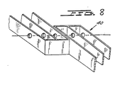
- the train can be used to accelerate charged particles or to drive an undulator/wiggler, such as the undulator/wiggler disclosed in U.S. Pat. No. 4,972,420, reproduced here as Figs. 8, 9A, 9B, 10A, 10B, and 11A, 11B.
- an undulator/wiggler such as the undulator/wiggler disclosed in U.S. Pat. No. 4,972,420, reproduced here as Figs. 8, 9A, 9B, 10A, 10B, and 11A, 11B.
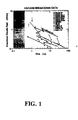
- Fig. 1 sets forth a compendium of the available data showing that when an electric field is applied to conventional electrode structures for a very short time, the regenerative events which ordinarily result in breakdown do not occur.
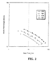
- Fig. 2 is a graph showing the vacuum breakdown delay time versus macroscopic field for various Nb cathode termperatures.
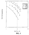
- Fig. 3 is a graph showing the vacuum breakdown delay versus macroscopic field for a Yba 2 CU 3 O 7-x extended cathode.
- Fig. 4 is a graph showing the pulse shape for a combination of 40 harmonics.
- Fig. 5 is a graph showing the pulse shape for a combination of 60 harmonics.
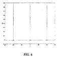
- Fig. 6 is a graph showing the pulse shape for a combination of 80 harmonics (3 pulses are shown in succession).
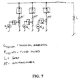
- Fig. 7 shows a diagram of a circuit for combining the component frequencies in accordance with the present invention.
- Fig. 8 shows an expanded view of the tips ends of two adjacent lines in the undulator driven by Fourier pulses in accordance with the present invention.
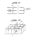
- Fig. 9A shows one element of the undulator used in the present invention
- Fig. 9B shows the tip end of one element of the undulator of Fig. 9A.
- Fig. 10A and 10B show the directions of the electric and magnetic fields in the tip of one element of the undulator.
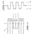
- Fig. 11A shows three successive pairs of lines in the undulator, giving a total of three full periods for the magnetic field shown in Fig. 11B.
- Equation (6) and Equation (8) appear to be quite different.
- a factor of 100 in field ( E ) improves the brilliance by a factor of 10.
- the two expressions are not (quantitatively) very different, because some E dependence, for a given emittance, is hidden in the parameter ⁇ ( S ), and because the range of current I in which the formulas are applicable affects the value of r .
- the data are consistent with the following scenario: As soon as the RF power is applied to the accelerating structure, the electric field starts to grow, at a rate proportional to the input power. After some time (of the order of a few thousand RF oscillations), the field reaches a value sufficiently high to extract some electrons from the conducting surface. This occurs at a relatively low electric field, well below the field required by Fowler-Nordheim tunneling. In fact, there are many mechanisms responsible for emission at "low" macroscopic fields. One of them, and indeed still the favorite, is the presence of microscopic sharp metallic protrusions. These protrustions are responsible for the conditioning effects. The conditioning of a structure is a gradual increase of the voltage breakdown, following the application of gradually increasing electric fields, well below breakdown. Actually, it appears that most of the electrons are emitted by i) a dislocation in the crystalline structure of the electrode of ii) a small piece of semiconductor or insulating material embedded in the electrode's surface.
- Beta is the ratio between the field calculated from FN emission and the actual macroscopic field. Typical values for very clean, well conditioned surfaces are of the order of 50-100, with a low value record of 20.
- the first problem with RF is that the maximum electric field is limited by regenerative processes, which become more and more effective (in producing an unwanted electron current) for longer and longer RF pulses.
- the second problem is the need for RF sources capable of extremely high power, to reach high accelerating fields. Many ingenious inventors have “compressed" the power available from RF sources, but their implementation is not trivial or inexpensive Present realistic limits of RF acceleration are in the range of 100 MV/m for frequencies of several gigahertz.
- Fig. 1 shows a compendium of the available data for different electrodes and from many different authors (from F. Villa, A. Luccio, "Test of a High Gradient, Low Emittance Electron Gun", Laser and Particle Beams (1997), vol. 15, No. 3, pp. 427-447). The general trend of higher field for shorter pulse duration is evident. The upright pointing arrows for two experimental points means that breakdown was not reached.
- the dashed area (i.e., for times less than 0.4 nanoseconds) is the region in which accelerating fields of the order of 3GV/m can be held safely with a good margin. Notice that 100 MV/m is reached (under pulse) for a time of the order of 100 ns.
- HTSC high temperature superconductors
- the magnetic field associated with the RF or the pulse could exceed the critical magnetic field ( H c ) of the material. If this happens, the material will become normal (non-superconducting).
- H c critical magnetic field
- the product B times lambda determines the wiggler or undulator denomination.
- This product controls the nature of the radiation produced by an electron beam passing through the undulator/wiggler, its degree of coherence, its power, and monochromaticity.
- Practical devices have a periodicity of a few centimeters, down to several millimeters.
- the maximum magnetic field does not exceed a few tenths of a Tesla, for a periodicity of one centimeter or thereabout, and in general, the smaller the period, the smaller the magnetic field.
- the magnetic field can be several Teslas even for very small periodicity.
- the present invention thus comprises the combination of a closely spaced train of fast electrical pulses (via a Fourier construction of pulses) which are used to drive the undulator/wiggler 40 of Figs. 8-11B to make extremely short wavelength undulators.
- a closely spaced train of fast electrical pulses via a Fourier construction of pulses
- the undulator/wiggler 40 of Figs. 8-11B to make extremely short wavelength undulators.
- a field of 10 Tesla exceeds the critical field of any known "conventional" superconductor.
- the value of H c is not the only factor limiting the electric field in a superconducting structure.
- Other phenomena limit the current carrying capability of HTSC to values close to 100 A/cm at a temperature not far below the normal to superconducting transition.
- a general mathematical theorem states that any continuous periodic function can be represented by a sum of orthogonal periodic functions, each periodic function with an appropriate coefficient.
- the frequency ⁇ is the fundamental periodicity of f ( t ).
- the function f ( t ) is represented approximately by a finite number of terms, since the value of a k decreases for large values of k, for any reasonable waveform.
- Eqs. 8a, 8b are valid for any arbitrary periodic f ( t ). This means that one can reconstruct bipolar pulse shapes, i.e., pulses with a positive and negative component.
- the peak power of the pulse is given by:
- a power compression ratio C n the ratio between the peak power of the pulse and the sum of the average power in the n sinusoidal frequencies: an approximation to C n is 2 n , as it will be seen later.
- the coefficient a k is of the order of t / T, up to a significantly large value of k .
- a k 2 t T A sin k ⁇ t T k ⁇ t T 2 T is the time interval between two adjacent (short) pulses of length t at the base. A is the peak amplitude of the pulse, which will be taken as unity from now on.
- Another pulse shape (exponential) has the following coefficients: It can be shown that a pulse of duration t repeated at a time interval T takes T / t terms to be represented with good approximation; and that the compression ratio, as defined in Eq. 10, is indeed 2 T / t .
- the number of terms can be estimated, i.e., the value of k , for which the harmonic amplitude is reduced by 1/ ⁇ ( ⁇ much greater than 1 ).
- k T 2 ⁇ t ⁇ - 1
- T / t 400, about 278 terms are required. If the sum is truncated at 100 terms, the pulse shape is still more than acceptable.
- the number of frequencies needed to represent the pulse shape of duration t at the repetition rate T depends essentially on t/T, and to the degree of approximation to the actual waveform that is needed by the particular application. There are many ways to generate these frequencies, at low power. Successive amplification of the low power sinusoid (possibly with variable gain) will be used to obtain the final amplitude of each harmonic. The amplified harmonics will be added to produce the final waveform.
- Mixers are devices with two inputs, of two different frequencies, and two outputs, consisting of the sum and the difference of the two frequencies.
- the dividers will produce the frequency values (in ⁇ units) of 64,32,16,8,4,2,1 (seven dividers).
- One multiplier will generate the frequency of 256.
- Summing and subtracting the frequencies above will generate all other frequencies.
- Dividers could be used as well: for example the frequency 48 ⁇ could be generated by summing 64+32 and dividing by two, or by summing 32+16.
- There are minimal nets that is, nets containing a minimum number of components) capable of generating all the required harmonics, and the actual net will be decided by considerations of frequency stability, phase stability, amplitude sensitivity, and cost/quality of the components.
- All of the 256 frequencies may need filtering before amplification, to insure that a pure sinusoid is amplified before being summed on the load.
- adjusting the gain of the (following) amplifying stages can compensate the amount of harmonic distortion.
- the phase, amplitude and purity of each harmonic can be controlled by a microprocessor that feeds back the results of a measurement of each quantity for every harmonic.
- a narrow bandwidth tuned filter in series with a power amplifier will protect the amplifier itself from the high voltage pulse, by allowing only one frequency to reach the amplifier output.
- the harmonics are generated at low power level and will be amplified by different components, depending on the range of frequencies, and the power level. This is a practical engineering task, easily solved by those skilled in the art. Suffice to say that solid state (MOSFETS or bipolar) are available at present up to few gigahertz, for power of the order of 100 watts. Vacuum tubes, triodes or tetrodes, are available up to a few gigahertz, for power levels much larger than the power available from solid state devices. This is especially true for pulsed system, i.e., for systems in which there is a burst of pulses, repeated at some interval much longer than the duration of the burst.
- MOSFETS solid state
- Vacuum tubes, triodes or tetrodes are available up to a few gigahertz, for power levels much larger than the power available from solid state devices. This is especially true for pulsed system, i.e., for systems in which there is a burst of pulses, repeated at some interval
- each pulse has an energy of 0.265 Joules.
- the peak power of the pulse is 2.65 gigawatts, and the average power of the pulse train, if continuous, is 6.6 megawatts. This average power is obtained by adding 256 sources. Therefore each source will supply roughly 26 kilowatts. If bursts of hundred pulses are repeated at a rate of 100 times/second, the average power of the pulse train will be 2.6 kilowatts.
- the actual circuitry necessary for this task depends upon the number of harmonics needed to approximate the pulse shape, pulse duration and repetition rate, and the power level.
- Power combiners are available commercially, in a broad range of power levels, frequencies, number of channels combined, etc. They are used, for example, when a single antenna is used to broadcast different transmitting stations. All of these elements are designed to combine power from different sources onto a load, or inversely as splitters, i.e., as devices to send power to different loads from a single source. Some combination of frequencies can be obtained at the amplification stage: the harmonics are synthesized at low power, and further amplified using (for instance) high frequency vacuum tubes.
- each vacuum tube can be driven with an admixture of different frequencies, appropriately chosen in order to compensate for phase, amplitude, distortion and gain at different frequencies.
- the number of frequencies, their distribution among different amplifiers etc. is a matter of good design practices in high power radio frequency electronics.
- the same criteria can be used if the pulses are relatively low power, in which case solid state amplifiers will replace vacuum tubes. Most likely the use of solid state amplifier will limit the maximum obtainable. If the mixing is done on low impedance, the final voltage can be increased by transforming up either the final pulse train or each individual harmonic.
- repetitive pulses also called comb generators
- Repetitive high voltage pulses generators are in the field of pulse power electronics, and can produce pulses of a few tens of nanoseconds, with spacing from the "square wave” (pulse duration equal to pulse spacing) to the "comb generator", where the pulses are spaced by a time much longer than their pulse length.
- Electronic components' specifications limit the pulse height, for short pulse duration, at the level of a few nanoseconds.
- each pulse shape is dictated by the particular switch and following pulse-forming network (in some cases the pulse shape can be modified, but only within a narrow range).
- the pulse length will be (nominally) 0.5 ns; the 40th harmonic will be 800 MHz. These are frequencies well within the capabilities of silicon devices (RF transistors or FET), up to the highest harmonic.
- the average power for the highest harmonic will be 0.43 watts, whilst the power at the lowest frequency will be 28 watts.
- the peak power of the pulser will be 20 kW, and the average power 200 Watts, which is equal to the sum of the power of all harmonics.
- the pulse shape will be as in Fig. 4, with 40 harmonics added. If 60 harmonics are added, the pulse shape will be as in Fig 5. Adding 80 frequencies the resulting pulse shape will be as in Fig. 6.
- each individual component can be done via a transformer (Fig. 7), whose primary and secondary are tuned (resonate) on the same frequency of the oscillator driving the load L. This is represented symbolically by two filters, on the primary and secondary respectively.
- the tranformers are represented as autotransformers in Fig 7.
- the transformer ratio is established by considering the particular waveform required at the load L.
- any arbitrary periodic function can be constructed to fit the requirements of the particular application.
- an open structure accelerator like the one described in U.S. Patent No. 4,893,089, the requirement is a bipolar pulse, or a pulse that approximately reproduces one cycle of a sinusoid at very high frequency. It is relevant to point out again that the harmonic mixing technique allows any arbitrary pulse shape to be reproduced, just by changing the amplitude of the harmonics.
- Another interesting feature of the Fourier combination is that it is possible to compensate for beam loading (longitudinal wakefield compensation). In conventional accelerators, this is done approximately by changing the phase of the electron bunch with respect to the phase of the radio frequency, so that the head of the bunch acquires a different energy than the tail. Especially in the first stages of acceleration, where the initial high current acceleration occurs, it may be necessary to raise the (unloaded) field, so that the longitudinal emittance stays low. The electric field must change in a time comparable to the length of the bunches. For multiple bunches acceleration, the pulse to pulse compensation will improve the energy spread (i.e. the longitudinal emittance).
- the load will be resonant at the lowest harmonic.
- a cable of a length of 6 meters (if vacuum insulated), open at both ends will resonate at 50 megahertz.
- a fast pulse will travel back and forth, being reflected at both ends of the cable. Therefore in any point of the cable length a pulse repeating at the rate of 50 megahertz will be seen.
- This particular configuration can be used when the load of the pulser is much greater than the impedance of the cable.
- the pulse shape will be distorted while it traverses the resonant load.
- the frequency dependence of the gain can occur because of losses, or because the structure leads to energy compression.
- One of the structures suggested for short pulse acceleration is the radial line. Normally it is composed of two parallel disks, with a small hole in the center. This structure is periodic, and in one embodiment it was open at the outer edge, to allow a fast pulse to be induced by an electron beam. The experiment was not successful, because (among other reasons) of instability of the driving electron beam.
- the radial line If the radial line is closed at the outer edge, it becomes a cavity, just like the conventional cavities of a linear accelerator.
- the difference between the radial line and a conventional cavity is in the ratio of gap to radius: of the order of 1 for conventional cavities, of the order of hundred or more for the radial line transformer.
- f 2 X ij ⁇ + m ⁇ l
Landscapes
- Physics & Mathematics (AREA)
- Engineering & Computer Science (AREA)
- Plasma & Fusion (AREA)
- Spectroscopy & Molecular Physics (AREA)
- Particle Accelerators (AREA)
Applications Claiming Priority (4)
| Application Number | Priority Date | Filing Date | Title |
|---|---|---|---|
| US400556 | 1982-07-21 | ||
| US14406899P | 1999-07-16 | 1999-07-16 | |
| US144068P | 1999-07-16 | ||
| US09/400,556 US6326861B1 (en) | 1999-07-16 | 1999-09-21 | Method for generating a train of fast electrical pulses and application to the acceleration of particles |
Publications (2)
| Publication Number | Publication Date |
|---|---|
| EP1069808A2 true EP1069808A2 (fr) | 2001-01-17 |
| EP1069808A3 EP1069808A3 (fr) | 2004-01-28 |
Family
ID=26841645
Family Applications (1)
| Application Number | Title | Priority Date | Filing Date |
|---|---|---|---|
| EP00850129A Withdrawn EP1069808A3 (fr) | 1999-07-16 | 2000-07-14 | Procédé de génération d'un train d'impulsions électriques rapides et application à l'accélération de particules |
Country Status (4)
| Country | Link |
|---|---|
| US (2) | US6326861B1 (fr) |
| EP (1) | EP1069808A3 (fr) |
| JP (1) | JP2001052900A (fr) |
| CA (1) | CA2313912C (fr) |
Cited By (2)
| Publication number | Priority date | Publication date | Assignee | Title |
|---|---|---|---|---|
| US6670767B2 (en) * | 1999-07-16 | 2003-12-30 | Feltech Corporation | Method for generating a train of fast electrical pulses and applying the pulses to an undulator |
| CN102869185A (zh) * | 2012-09-12 | 2013-01-09 | 中国原子能科学研究院 | 一种强流紧凑型回旋加速器腔体锻炼方法 |
Families Citing this family (8)
| Publication number | Priority date | Publication date | Assignee | Title |
|---|---|---|---|---|
| JP2001125532A (ja) * | 1999-10-26 | 2001-05-11 | Nec Corp | 電界電子放出装置の駆動方法 |
| WO2004030424A2 (fr) * | 2002-09-27 | 2004-04-08 | Scantech Holdings, Llc | Accelerateur de particules a grande plage de commande d'energie |
| RU2265973C1 (ru) * | 2004-04-12 | 2005-12-10 | Государственное научное учреждение "Научно-исследовательский институт ядерной физики при Томском политехническом университете министерства образования Российской Федерации" | Линейный индукционный ускоритель |
| CN1998059A (zh) * | 2004-06-04 | 2007-07-11 | 马萨诸塞州技术研究院 | 非轴对称带电粒子束系统 |
| US9099271B2 (en) * | 2011-08-02 | 2015-08-04 | The Board Of Trustees Of The Leland Stanford Junior University | Method and system for operating electron guns in magnetic fields |
| KR101958849B1 (ko) * | 2012-05-31 | 2019-03-15 | 지멘스 악티엔게젤샤프트 | 빔하전 입자를 패킷타이징하기 위한 방법 및 디바이스 |
| US11209478B2 (en) * | 2018-04-03 | 2021-12-28 | Applied Materials, Inc. | Pulse system verification |
| CN115460757B (zh) * | 2022-09-30 | 2025-07-15 | 兰州泰基离子技术有限公司 | 用于医用重离子加速器的束流引出高压控制方法及装置 |
Citations (3)
| Publication number | Priority date | Publication date | Assignee | Title |
|---|---|---|---|---|
| US3359452A (en) | 1965-10-14 | 1967-12-19 | Quentin A Kerns | Resonator for supporting non-sinus-oidal preiodic waveforms |
| US4893089A (en) | 1988-09-14 | 1990-01-09 | Harris Blake Corporation | Pulse power linac |
| US4972420A (en) | 1990-01-04 | 1990-11-20 | Harris Blake Corporation | Free electron laser |
Family Cites Families (32)
| Publication number | Priority date | Publication date | Assignee | Title |
|---|---|---|---|---|
| US4155017A (en) * | 1977-11-09 | 1979-05-15 | The United States Of America As Represented By The Secretary Of The Army | Sharpening high power pulses |
| US4598415A (en) | 1982-09-07 | 1986-07-01 | Imaging Sciences Associates Limited Partnership | Method and apparatus for producing X-rays |
| US4888556A (en) | 1988-06-21 | 1989-12-19 | The United States Of America As Represented By The United States Department Of Energy | Linear induction accelerator and pulse forming networks therefor |
| US5796219A (en) | 1988-07-15 | 1998-08-18 | Shimadzu Corp | Method and apparatus for controlling the acceleration energy of a radio-frequency multipole linear accelerator |
| US4918325A (en) * | 1988-12-08 | 1990-04-17 | The United States Of America As Represented By The Secretary Of The Air Force | Fast risetime pulse power system |
| US5042058A (en) * | 1989-03-22 | 1991-08-20 | University Of California | Ultrashort time-resolved x-ray source |
| JPH02272379A (ja) * | 1989-04-14 | 1990-11-07 | Hitachi Ltd | 高周波パルスの発生および試料の核磁気共鳴励起の方法および装置 |
| JPH0312404A (ja) * | 1989-06-09 | 1991-01-21 | Nisshin Steel Co Ltd | 硬質高分子薄膜の形成方法 |
| US5089785A (en) | 1989-07-27 | 1992-02-18 | Cornell Research Foundation, Inc. | Superconducting linear accelerator loaded with a sapphire crystal |
| WO1991003084A1 (fr) * | 1989-08-25 | 1991-03-07 | Madey John M J | Oscillateur a laser a electrons libres de spectroscopie a resolution spectrale etroite et a resolution rapide simultanees |
| US5150067A (en) | 1990-04-16 | 1992-09-22 | Mcmillan Michael R | Electromagnetic pulse generator using an electron beam produced with an electron multiplier |
| US5239309A (en) * | 1991-06-27 | 1993-08-24 | Hughes Aircraft Company | Ultra wideband radar employing synthesized short pulses |
| JPH05149994A (ja) * | 1991-11-27 | 1993-06-15 | Fujikura Ltd | 部分放電検出センサ |
| US5381072A (en) | 1992-02-25 | 1995-01-10 | Varian Associates, Inc. | Linear accelerator with improved input cavity structure and including tapered drift tubes |
| US5659228A (en) | 1992-04-07 | 1997-08-19 | Mitsubishi Denki Kabushiki Kaisha | Charged particle accelerator |
| US5347209A (en) * | 1992-08-21 | 1994-09-13 | The United States Of America As Represented By The United States Department Of Energy | Voltage control in pulsed system by predict-ahead control |
| JPH06252097A (ja) * | 1993-02-25 | 1994-09-09 | Hitachi Ltd | プラズマエッチング装置 |
| US5422549A (en) | 1993-08-02 | 1995-06-06 | The University Of Chicago | RFQ device for accelerating particles |
| JPH0831599A (ja) * | 1994-07-15 | 1996-02-02 | Japan Atom Energy Res Inst | 無理数次高調波を発生するアンジュレータに用いられる磁場発生装置 |
| JP2925965B2 (ja) | 1994-12-15 | 1999-07-28 | 住友重機械工業株式会社 | 荷電粒子ビームの集群方法とその装置 |
| US5637966A (en) | 1995-02-06 | 1997-06-10 | The Regents Of The University Of Michigan | Method for generating a plasma wave to accelerate electrons |
| US5789876A (en) | 1995-09-14 | 1998-08-04 | The Regents Of The Univeristy Of Michigan | Method and apparatus for generating and accelerating ultrashort electron pulses |
| US5757146A (en) | 1995-11-09 | 1998-05-26 | Carder; Bruce M. | High-gradient compact linear accelerator |
| US6025911A (en) * | 1995-11-14 | 2000-02-15 | University Of New Mexico | Broadband ultrashort pulse measuring device using non-linear electronic components |
| US5789865A (en) | 1996-05-01 | 1998-08-04 | Duly Research Inc. | Flat-field planar cavities for linear accelerators and storage rings |
| US5736709A (en) * | 1996-08-12 | 1998-04-07 | Armco Inc. | Descaling metal with a laser having a very short pulse width and high average power |
| US5889797A (en) * | 1996-08-26 | 1999-03-30 | The Regents Of The University Of California | Measuring short electron bunch lengths using coherent smith-purcell radiation |
| US5744919A (en) | 1996-12-12 | 1998-04-28 | Mishin; Andrey V. | CW particle accelerator with low particle injection velocity |
| US6098568A (en) * | 1997-12-01 | 2000-08-08 | Applied Materials, Inc. | Mixed frequency CVD apparatus |
| US6043607A (en) * | 1997-12-16 | 2000-03-28 | Applied Materials, Inc. | Apparatus for exciting a plasma in a semiconductor wafer processing system using a complex RF waveform |
| JP3857403B2 (ja) * | 1997-12-24 | 2006-12-13 | 住友重機械工業株式会社 | 加速器用高周波パルス電圧発生方法及び装置 |
| US6326861B1 (en) * | 1999-07-16 | 2001-12-04 | Feltech Corporation | Method for generating a train of fast electrical pulses and application to the acceleration of particles |
-
1999
- 1999-09-21 US US09/400,556 patent/US6326861B1/en not_active Expired - Fee Related
-
2000
- 2000-07-14 JP JP2000215152A patent/JP2001052900A/ja active Pending
- 2000-07-14 EP EP00850129A patent/EP1069808A3/fr not_active Withdrawn
- 2000-07-14 CA CA002313912A patent/CA2313912C/fr not_active Expired - Fee Related
-
2001
- 2001-10-30 US US09/984,410 patent/US6670767B2/en not_active Expired - Fee Related
Patent Citations (3)
| Publication number | Priority date | Publication date | Assignee | Title |
|---|---|---|---|---|
| US3359452A (en) | 1965-10-14 | 1967-12-19 | Quentin A Kerns | Resonator for supporting non-sinus-oidal preiodic waveforms |
| US4893089A (en) | 1988-09-14 | 1990-01-09 | Harris Blake Corporation | Pulse power linac |
| US4972420A (en) | 1990-01-04 | 1990-11-20 | Harris Blake Corporation | Free electron laser |
Non-Patent Citations (4)
| Title |
|---|
| F. VILLA; A. LUCCIO: "Test of a High Gradient, Low Emittance Electron Gun", LASER AND PARTICLE BEAMS, vol. 15, no. 3, 1997, pages 427 - 447 |
| N. NEWMANN; W.G. LYONS, J. SUPERCONDUCTOR, vol. 6, no. 3, 1993, pages 119 - 159 |
| S. I. SHKURATOV, IEEE TRANSACTIONS ON DIELECTRIC AND ELECTRICAL INSULATION, vol. 2, no. 2, April 1995 (1995-04-01) |
| T STRINIVASAN-RAO; J. SMEDLEY: "Table Top, pulsed, relativistic electron gun with GV/M gradient", PROCEEDINQS OF ADVANCED ACCELERATOR CONCEPT, (SEVENTH WORKSHOP) AIP CONFERENCE PROCEEDINQS 398, October 1996 (1996-10-01) |
Cited By (2)
| Publication number | Priority date | Publication date | Assignee | Title |
|---|---|---|---|---|
| US6670767B2 (en) * | 1999-07-16 | 2003-12-30 | Feltech Corporation | Method for generating a train of fast electrical pulses and applying the pulses to an undulator |
| CN102869185A (zh) * | 2012-09-12 | 2013-01-09 | 中国原子能科学研究院 | 一种强流紧凑型回旋加速器腔体锻炼方法 |
Also Published As
| Publication number | Publication date |
|---|---|
| US6670767B2 (en) | 2003-12-30 |
| EP1069808A3 (fr) | 2004-01-28 |
| CA2313912A1 (fr) | 2001-01-16 |
| JP2001052900A (ja) | 2001-02-23 |
| US20020039005A1 (en) | 2002-04-04 |
| CA2313912C (fr) | 2008-09-09 |
| US6326861B1 (en) | 2001-12-04 |
Similar Documents
| Publication | Publication Date | Title |
|---|---|---|
| Yalandin et al. | Generation of powerful subnanosecond microwave pulses in the range of 38-150 GHz | |
| Blank et al. | Experimental investigation of W-band (93 GHz) gyroklystron amplifiers | |
| US6670767B2 (en) | Method for generating a train of fast electrical pulses and applying the pulses to an undulator | |
| Blank et al. | Demonstration of a 10 kW average power 94 GHz gyroklystron amplifier | |
| Felch et al. | Recent ITER-relevant gyrotron tests | |
| Rozental et al. | Nonstationary processes in an X-band relativistic gyrotron with delayed feedback | |
| Blank et al. | Experimental demonstration of a W-band (94 GHz) gyrotwystron amplifier | |
| Peter et al. | High-gain X-band dielectric Cherenkov maser | |
| US7285915B2 (en) | Electron gun for producing incident and secondary electrons | |
| Rostov et al. | High-efficiency relativistic generators of nanosecond pulses in the millimeter-wavelength range | |
| Litvin et al. | Plasma high-current generator of wideband high-power microwaves with magnetic self-insulation | |
| Grabowski et al. | Observation of the cross-excitation instability in a relativistic backward wave oscillator | |
| Wilson | High pulse power rf sources for linear colliders | |
| Peratt et al. | A high-power reflex triode microwave source | |
| Othman et al. | High Gradient and rf breakdown measurements in a millimeter-wave accelerating cavity | |
| Schamiloglu | Perspectives on directed energy microwaves after the first 50 years | |
| Gilgenbach et al. | Intense electron beam cyclotron masers with microsecond pulselengths | |
| Einat et al. | Free-electron maser driven by a two-stage ferroelectric electron gun | |
| Le Sage et al. | A high brightness, X-band photoinjector for the production of coherent synchrotron radiation | |
| Serlin et al. | RF extraction issues in the relativistic klystron amplifiers | |
| Vikharev et al. | High-Gradient Sub-Thz Accelerating Structures Powered by Cherenkov Superradiance Pulses | |
| Vikharev et al. | High-Gradient Structures for Acceleration of Electrons by Short-Wave Pulses of Čerenkov Superradiance | |
| Kuzikov | Short Pulse High-Gradient Accelerating Structures | |
| Leontyev et al. | Experimental Investigations of Multi-Frequency Operation Regimes of a High-Current Relativistic Gyrotron with Elongated Interaction Space | |
| Ju et al. | A Relativistic Coaxial Klystron Amplifier for Phase-Locked High Power Microwave Generation |
Legal Events
| Date | Code | Title | Description |
|---|---|---|---|
| PUAI | Public reference made under article 153(3) epc to a published international application that has entered the european phase |
Free format text: ORIGINAL CODE: 0009012 |
|
| AK | Designated contracting states |
Kind code of ref document: A2 Designated state(s): AT BE CH CY DE DK ES FI FR GB GR IE IT LI LU MC NL PT SE |
|
| AX | Request for extension of the european patent |
Free format text: AL;LT;LV;MK;RO;SI |
|
| 17P | Request for examination filed |
Effective date: 20010704 |
|
| PUAL | Search report despatched |
Free format text: ORIGINAL CODE: 0009013 |
|
| AK | Designated contracting states |
Kind code of ref document: A3 Designated state(s): AT BE CH CY DE DK ES FI FR GB GR IE IT LI LU MC NL PT SE |
|
| AX | Request for extension of the european patent |
Extension state: AL LT LV MK RO SI |
|
| AKX | Designation fees paid |
Designated state(s): AT BE CH CY DE DK ES FI FR GB GR IE IT LI LU MC NL PT SE |
|
| 17Q | First examination report despatched |
Effective date: 20080417 |
|
| RIC1 | Information provided on ipc code assigned before grant |
Ipc: H05H 7/02 20060101AFI20110915BHEP |
|
| STAA | Information on the status of an ep patent application or granted ep patent |
Free format text: STATUS: THE APPLICATION IS DEEMED TO BE WITHDRAWN |
|
| 18D | Application deemed to be withdrawn |
Effective date: 20140201 |