EP1069649B1 - Wellenleiter für ein Mikrowellen-Füllstandsmessgerät - Google Patents
Wellenleiter für ein Mikrowellen-Füllstandsmessgerät Download PDFInfo
- Publication number
- EP1069649B1 EP1069649B1 EP99113686A EP99113686A EP1069649B1 EP 1069649 B1 EP1069649 B1 EP 1069649B1 EP 99113686 A EP99113686 A EP 99113686A EP 99113686 A EP99113686 A EP 99113686A EP 1069649 B1 EP1069649 B1 EP 1069649B1
- Authority
- EP
- European Patent Office
- Prior art keywords
- waveguide
- conductors
- conductor
- signal
- signal conductor
- Prior art date
- Legal status (The legal status is an assumption and is not a legal conclusion. Google has not performed a legal analysis and makes no representation as to the accuracy of the status listed.)
- Expired - Lifetime
Links
- 239000004020 conductor Substances 0.000 claims description 142
- 239000000523 sample Substances 0.000 claims description 56
- 230000008878 coupling Effects 0.000 claims description 29
- 238000010168 coupling process Methods 0.000 claims description 29
- 238000005859 coupling reaction Methods 0.000 claims description 29
- 239000004033 plastic Substances 0.000 claims description 24
- 229920003023 plastic Polymers 0.000 claims description 24
- 239000002184 metal Substances 0.000 claims description 11
- 238000005259 measurement Methods 0.000 description 13
- 239000000463 material Substances 0.000 description 9
- 238000010276 construction Methods 0.000 description 5
- 238000009434 installation Methods 0.000 description 5
- 125000006850 spacer group Chemical group 0.000 description 5
- 230000035945 sensitivity Effects 0.000 description 4
- 230000000149 penetrating effect Effects 0.000 description 3
- 239000004813 Perfluoroalkoxy alkane Substances 0.000 description 2
- 238000002592 echocardiography Methods 0.000 description 2
- 230000003993 interaction Effects 0.000 description 2
- 238000004519 manufacturing process Methods 0.000 description 2
- 229920011301 perfluoro alkoxyl alkane Polymers 0.000 description 2
- 229920002493 poly(chlorotrifluoroethylene) Polymers 0.000 description 2
- 239000005023 polychlorotrifluoroethylene (PCTFE) polymer Substances 0.000 description 2
- 229920001343 polytetrafluoroethylene Polymers 0.000 description 2
- 239000004810 polytetrafluoroethylene Substances 0.000 description 2
- 229920001780 ECTFE Polymers 0.000 description 1
- 239000004812 Fluorinated ethylene propylene Substances 0.000 description 1
- 239000002033 PVDF binder Substances 0.000 description 1
- 239000004696 Poly ether ether ketone Substances 0.000 description 1
- 239000004734 Polyphenylene sulfide Substances 0.000 description 1
- 229910000831 Steel Inorganic materials 0.000 description 1
- 239000004809 Teflon Substances 0.000 description 1
- 229920006362 Teflon® Polymers 0.000 description 1
- 238000009825 accumulation Methods 0.000 description 1
- 230000002411 adverse Effects 0.000 description 1
- 238000005452 bending Methods 0.000 description 1
- JUPQTSLXMOCDHR-UHFFFAOYSA-N benzene-1,4-diol;bis(4-fluorophenyl)methanone Chemical compound OC1=CC=C(O)C=C1.C1=CC(F)=CC=C1C(=O)C1=CC=C(F)C=C1 JUPQTSLXMOCDHR-UHFFFAOYSA-N 0.000 description 1
- 230000015572 biosynthetic process Effects 0.000 description 1
- 230000000903 blocking effect Effects 0.000 description 1
- 238000001514 detection method Methods 0.000 description 1
- 239000003989 dielectric material Substances 0.000 description 1
- 230000003670 easy-to-clean Effects 0.000 description 1
- 230000000694 effects Effects 0.000 description 1
- 230000005672 electromagnetic field Effects 0.000 description 1
- 229920000840 ethylene tetrafluoroethylene copolymer Polymers 0.000 description 1
- 230000000763 evoking effect Effects 0.000 description 1
- 239000011810 insulating material Substances 0.000 description 1
- 238000000034 method Methods 0.000 description 1
- 229920009441 perflouroethylene propylene Polymers 0.000 description 1
- 229920002530 polyetherether ketone Polymers 0.000 description 1
- 229920000069 polyphenylene sulfide Polymers 0.000 description 1
- 229920000915 polyvinyl chloride Polymers 0.000 description 1
- 229920002620 polyvinyl fluoride Polymers 0.000 description 1
- 229920002981 polyvinylidene fluoride Polymers 0.000 description 1
- 238000002310 reflectometry Methods 0.000 description 1
- 239000010959 steel Substances 0.000 description 1
Images


Classifications
-
- H—ELECTRICITY
- H01—ELECTRIC ELEMENTS
- H01Q—ANTENNAS, i.e. RADIO AERIALS
- H01Q1/00—Details of, or arrangements associated with, antennas
- H01Q1/12—Supports; Mounting means
- H01Q1/22—Supports; Mounting means by structural association with other equipment or articles
- H01Q1/225—Supports; Mounting means by structural association with other equipment or articles used in level-measurement devices, e.g. for level gauge measurement
-
- G—PHYSICS
- G01—MEASURING; TESTING
- G01F—MEASURING VOLUME, VOLUME FLOW, MASS FLOW OR LIQUID LEVEL; METERING BY VOLUME
- G01F23/00—Indicating or measuring liquid level or level of fluent solid material, e.g. indicating in terms of volume or indicating by means of an alarm
- G01F23/22—Indicating or measuring liquid level or level of fluent solid material, e.g. indicating in terms of volume or indicating by means of an alarm by measuring physical variables, other than linear dimensions, pressure or weight, dependent on the level to be measured, e.g. by difference of heat transfer of steam or water
- G01F23/28—Indicating or measuring liquid level or level of fluent solid material, e.g. indicating in terms of volume or indicating by means of an alarm by measuring physical variables, other than linear dimensions, pressure or weight, dependent on the level to be measured, e.g. by difference of heat transfer of steam or water by measuring the variations of parameters of electromagnetic or acoustic waves applied directly to the liquid or fluent solid material
- G01F23/284—Electromagnetic waves
-
- H—ELECTRICITY
- H01—ELECTRIC ELEMENTS
- H01Q—ANTENNAS, i.e. RADIO AERIALS
- H01Q13/00—Waveguide horns or mouths; Slot antennas; Leaky-waveguide antennas; Equivalent structures causing radiation along the transmission path of a guided wave
- H01Q13/08—Radiating ends of two-conductor microwave transmission lines, e.g. of coaxial lines, of microstrip lines
Definitions
- the invention relates to a waveguide for a Level measuring device for determining the level of a Medium in a container by means of guided microwave pulse signals.
- the invention relates to a such waveguide of a microwave level measuring device, whose probe part is immersed in the medium to be measured and on the the measuring signals to the medium and there reflected echo signals are guided.
- the waveguide connected electronic measuring circuit generated and the Waveguide usually via a cable connection, preferably a coaxial cable, routed.
- the cable comes with a Connecting part of the waveguide connected so that the Signals coupled into the waveguide and along the Partially sent to the medium.
- a the Level marking upper or boundary surface of the medium reflects the pulse signals, which are then called so-called Echo signals on the waveguide to the level gauge to be led back.
- the echo signals are the Superimposed emitted microwave signals, and from the thus formed total signal becomes the time between emitting the microwave signals and the arrival of the Echo signals passed, determined.
- She is a measure of that Path of the microwave signals from the level gauge to Surface of the medium and back and serves, with known Propagation speed of the signals on the probe part of the waveguide, to determine the required level.
- This type of level measurement, on a Runtime measurement with guided microwave pulse signals is also under the term "TDR (Time Domain Reflectometry) "known.
- An immersed in the medium probe part of the Waveguide comprises at least one so-called ladder in actual meaning.
- the term “Ladder” in this sense can be either signal conductor, or also called “hot” conductor, and so-called “shield conductor” include, one of the high-frequency Pulse signals evoked field between the conductors builds. Because of the high-frequency signals give the Designations "signal conductor” and “shield conductor” only one current state again.
- a single-conductor waveguide includes only one Signal conductor. If necessary and depending on the application can a probe portion of a waveguide of any number of signal and shield conductors.
- the first criterion of the above listing determines if and to what extent disturbing reflections in the area of Coupling occur.
- the second criterion determines a kind of global Sensitivity of the waveguide and depends significantly on the materials used for the waveguide. It indicates the energy of the microwave signals at the Surface of the medium for the signals reflected there is available and if and how good that Level gauge useful echo even with interference signals can be identified.
- the first and second criteria determine the so-called Block distance with which the initial length of the Waveguide is referred to after coupling, on the without disproportionate effort no meaningful Detection of the desired useful signal can be done.
- the third criterion determines whether and how strong the Level gauge on deposits on or approach to the Probe part reacts.
- a waveguide of this kind is also under the Name "Sommerfeld ladder" known.
- the one-conductor waveguide not for all applications suitable.
- the measurement serving electrical and magnetic field forms between the individual conductor the probe part and, for example, a container wall, so that the field around the waveguide around a relative big stretch shows.
- Couplings (and couplings) of signals into (or out of) the one-conductor waveguide are relatively difficult to realize as a significant Part of the signal energy at the coupling or other Changes in the geometry of the waveguide reflected becomes.
- the single-conductor waveguide is a significant part of Signal energy for the construction of the broad field consumed, that is radiated, is only a small Part of the signal energy for a level measurement for Available.
- the radiated energy in the Attachment socket due to multiple reflections lead to unwanted Nachschwing binen.
- Waveguide has one Probe part on with a signal and a shield conductor in coaxial arrangement.
- a mostly rod-shaped signal conductor is concentric from the mostly tubular shield conductor surrounded, so that of the microwave signals caused field only in the, usually narrow annulus formed between the signal conductor and the shield conductor.
- the medium penetrating there calls that for the determination the level desired echo signal forth.
- Coaxial waveguides are characterized by an effective Signal coupling off. Because of the microwave measurement signal generated field on the area of the annulus between the Ladders is limited, do not occur unwanted Abstraction effects on. There is no danger of disturbing Interactions with nozzles or other internals in the Container. The blocking distance is low and the function of the Coaxial waveguide does not depend on its installation position.
- the measuring signal between the signal conductor and the surrounding it Umbrella conductor led, whereby in the annulus between the conductors penetrating medium causes the useful signal. It is therefore possible in a the connecting part of the Waveguide facing area with appropriate measures to close the annulus and opposite the Shut off penetrating medium.
- the Annular space in the desired area by suitable plastic filled, so that in the filled section the relevant length of the probe part not for measurements Available. This desired laying of the highest Measuring point of the level measurement of the attachment of Waveguide continues on the container, also becomes “inactive length" called the waveguide.
- WO-A 98/25109 is such a coaxial waveguide for a level gauge described and shown at a tubular provided with longitudinal slots Shielding conductor encloses a rod-shaped signal conductor.
- the tubular shielding conductor surrounds the signal conductor in essential over its entire length.
- the signal conductor as well as the shielding conductor are of an insulating Material wrapped around, which is also the annulus between the two Fills ladders.
- the electromagnetic field used for the Level measurement is required, forms only due to the longitudinal slots around the waveguide, however over the length of the waveguide not evenly and not in the desired manner.
- WO-A 98/05931 is another waveguide for a Medstandsmeß réelle known, in which as a probe part two or more essentially in a common plane lying conductors are used. The medium to be measured is located around the ladder and between them.
- the probe part of this level measuring device comprises "U-shaped" arranged ladder, where it is essentially on the from the measuring signals between the parallel and with each other connected ladder field arrives.
- a waveguide indicate for a level gauge, which is characterized by It is characterized by simple structure, which has the advantages of Single-wire and well-known multiwire waveguide unites, by showing no interaction with vessel installations, whose inactive length is easily adjustable, and in a simple way of deposits or deposits too is clean.
- the waveguide after The invention is a carrier body made of plastic intended.
- the invention is based on the idea, multiple Ladder in a substantially parallel arrangement are insensitive to interference, in to surround a probe part of the waveguide in such a way that Deposits or deposits between the conductors prevented and that in addition the probe part on simple Way can be cleaned. Because of its construction is the waveguide according to the invention easily and safely too assemble.
- Another advantage of the invention is that by the special design of the coupling (or decoupling) the measuring signals and the possibility of special Impedance matching the inactive length of the waveguide in desired way and set with simple means can be.
- the waveguide can therefore be so short be executed that he is suitable for measurements in such flat containers in which microwave ovens were previously or radar level gauges can not be measured.
- the entrance mentioned criteria e.g. the global sensitivity Determine the waveguide
- the entrance mentioned criteria e.g. the global sensitivity Determine the waveguide
- the invention for the particular application in the desired manner be optimized.
- the number of conductors and the material of the carrier body of the probe part the relation of the microwave energy in Inside and outside of the probe part, whereby e.g. the susceptibility of the waveguide to approach in Depending on the medium can be adjusted.
- the Waveguide may also have a geometry of the Container or determined by the medium to be measured shape accept. His probe part, in the medium to be measured dips, can assume any length in itself.
- FIG. 1 waveguide 100 after the Invention has a connection part 110, a probe part 130 and a fixing part 140 for fixing the Waveguide 100 on or in a not shown here Container on where the level of the therein Medium should be determined.
- connection part 110 comprises, as shown in Fig. 1, outer and substantially can-shaped housing 112, the head-side opening 113 of a closure member 114th is closed.
- a plug 115th attached, for example, a commercially available plug, preferably a BNC plug, which is in a corresponding Bore or connection opening 117 in the closure member 114th intervenes. It is also conceivable, such a connector 115th to use, which is threaded, so that he then into a corresponding internal thread in the opening 117th can be screwed in the closure member 114.
- a connector 115th to use, which is threaded, so that he then into a corresponding internal thread in the opening 117th can be screwed in the closure member 114.
- other types of attachment the plug 115 in the closure part possible if one mechanically safe and possibly also dense connection of the Plug 115 is ensured to the closure member 114.
- the closure member 114 is preferably in the outer housing 112 fastened, for example, with a External thread is provided in a corresponding Internal thread of the housing 112 engages.
- a External thread is provided in a corresponding Internal thread of the housing 112 engages.
- any other connection conceivable, provided that the Closure 114 securely fixed in the housing 112 and, if required, seals.
- the housing 112, the closure member 114 and the plug 115th are preferably made of metal. But you can also go out other suitable materials, e.g. Plastic, although it should be noted that the closure member 114 via the plug 115th provided high-frequency measurement signals on in the probe part 130 arranged conductors 131 a and b must continue.
- the ability to guide or direct the RF signals then also a closure member 114 made of plastic or a Plug 115 have plastic.
- a rear side of the plug 115 arranged here schematically illustrated cable 116 connects the waveguide 100 with a not shown here, electronic measuring circuit.
- There generated measuring signals are over a "hot wire" of the Coaxial cable 116 is placed on a contact pin 115a, the in direct contact with a preferably rod-shaped Signal conductor 119 passed in the probe part 130.
- a contact pin 115a is inside the closure member 114 of surrounded by a cone 118 and thereby by the closure member 114, that with a shield conductor of the coaxial cable 116 in Connection is isolated.
- the cone 118 is preferably made of plastic, but it can also be made of other suitable Material exist.
- a head portion 120 of a support body 132nd In the interior of the housing 112, more precisely in a plug 115 opposite part of the opening 113 and in the direction seen on the probe part 140, joins the Closure 114 a head portion 120 of a support body 132nd at.
- This head part 120 is in a correspondingly shaped Area of the opening 113 of the housing 112 through the Closure 114 held.
- the head part 120 is in Actually meaning part of the support body 132, in the signal conductor 119 and the shield conductors 131a and 131b are embedded.
- the carrier body 132 consists of a dielectric material, for example a PEEK, PPS or PTFE plastic. Other suitable materials are for. B. ECTFE, ETFE, FEP, PCTFE, PFA, PVDF, PVF, PVC, being used in the Food industry carrier body made of PTFE, PCTFE and PFA plastic are preferred.
- the signal conductor 119 extends from a Closure 114 opposite area of the Part 130 through the cone 118 through and over the Head portion 120, as mentioned, to the contact pin 115 a of the plug 115.
- the signal conductor 119 In the probe part 130 is the signal conductor 119 on its entire length from the material of the Surrounding body 132 and thereby of the, im Embodiment of FIG. 1 two parallel to him in the Carrier body arranged screen conductors 131a and 131b isolated.
- signal conductor and shield conductor are used here, as already mentioned, not in the usual used electrotechnical sense, but they serve here for a better distinction of the individual conductors from each other. These designations are based on the Name of the signal and shield conductor of the coaxial cable 116, with which the measuring signals to the waveguide be introduced. In an innovative way, this becomes Coaxial arrangement for the conductors 119 and 131a and 131b maintained so that the signal conductor 119 for connection to the contact pin 115a between the shield conductors 131a and 131b can be passed.
- the shielding conductor 131 a and 131b connected to a crown-shaped coupling part 121, about that in turn with the closure member 114, more precisely said with its inner face 114a, and above again with the shield conductor of the coaxial cable 16 in Standing in contact.
- the coupling part 121 a annular, through a cylindrical portion 121a illustrated base part, which in two point-like Forts 121b and 121c expires. Together form the cylindrical portion 121a and the extensions 121b and 121c the mentioned form of a crown, at the tips of which Shielding conductors 131a and 131b are attached.
- This particular and preferred construction of the coupling part 121 can be very easy to produce from a tubular component, in which behind the desired base each oblique sections from outside to inside to a longitudinal axis of the pipe section is executed. Especially in the case where more than two shielding conductors are provided for the waveguide, can be in a simple way crown-shaped coupling parts 121 with the desired number of tips.
- the above described inactive length of the waveguide 100th check can be compared with a picture 1 modified form of the coupling part 121, in particular of its base part 121a, the above described inactive length of the waveguide 100th check.
- the base part 121a of the Coupling part 121 in the direction of the probe part 130 to about the attachment part 140 are extended so that the signal conductor 119 to there from the base portion 121a coaxial is enclosed. This enclosed area of the Signal conductor is not available for a measurement and determines the inactive length.
- the Invention but also a very short inactive length of Waveguide realize by, for example, the Coupling 121 is designed as a thin ring, the, transverse arranged to the longitudinal axis of the screen conductors 131a and 131b, connecting them together.
- the signal conductor 119, the shield conductors 131a and 131b and the coupling part 121 are made of electrically conductive material, preferably made of metal. But there are others too electrically conductive materials conceivable.
- the probe part 130 shown in FIG. 1 is a particular embodiment of the waveguide 100 after the invention. He can depending on the application and container e.g. be longer or of a different geometric shape. Also the attachment of the waveguide 100 can play a role play. For simplicity and because they are in themselves for the Invention is not relevant and to underline the versatile applicability of the waveguide 100 is in Fig. 1 is a "simple" attachment member 140 with a mounted external thread 141 shown in a corresponding internal thread of a suitable nozzle engages the container. There are others, too Types of attachment of the waveguide feasible, such. Flanges or connectors, provided they are mechanically reliable and possibly tight attachment of the Ensure waveguide 100 on or in the container.
- the carrier body 132 of the Waveguide 100 of FIG. 1 is a substantially oval Cross-sectional shape.
- the shielding conductors 131a, 131b and the centrally located signal conductor 119th are the shielding conductors 131a, 131b and the centrally located signal conductor 119th.
- the Advantage of this oval cross-sectional shape is that they adequate mechanical stability with relatively little Material for the carrier body 132 and thus small Power losses along the probe part 130 manages.
- the probe part 132 thus obtained is easy to clean and is suitable for corresponding plastic especially for a use in the food industry.
- the Probe member 132 having such an oval cross section can without large additional manufacturing effort of any length getting produced.
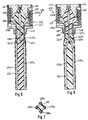
- Fig. 3 is a second preferred embodiment of the waveguide according to the invention.
- This Waveguide 200 is similar to waveguide 100 of FIG. 1 from a connection part 210, a fastening part 240th and a probe part 230 in which two Shielding conductor 231a and 231b and a signal conductor 219th are provided.
- Closure 214 may, as in the embodiment of Fig. 1, a coaxial cable to be connected via the the measuring signals are performed.
- the probe part 230 has, in contrast to the waveguide 100 according to FIGS. 1 and 2, a carrier body 232 with diamond-shaped cross section.
- a carrier body 232 with diamond-shaped cross section.
- crown-shaped Coupling 221 with its extensions 221a and 221b, with the shield conductors 231a and 231b are connected.
- the coupling part 221 with the Closure 214 connected, so that the coupling part 221 attached shielding conductor 231a and 231b with a Shielding conductor of the coaxial cable in contact.
- the Connection of the signal conductor 219 with a signal conductor of Coaxial cable is preferably similar to that shown in FIG Fig. 1 executed.
- An attachment part 240 corresponds to Shape and function of the fastening part 140 of FIG. 1.
- the carrier body 232 thickens, which is illustrated in Fig. 3 by "230a” and covers the tips of the extensions 221b and 221c of the Coupling 221. This ensures a safe mechanical protection for the attached screen conductors 231a and 231b. If desired, the coupling part 221 with a thin, not shown here plastic hose be wrapped around it, not to him directly to the medium to be measured suspend.
- FIG. 4 shows the waveguide 200 in a side view in which inner edges are drawn.
- connection part 210 is the closure member 214 with an opening or socket for an indicated here plug 215, for example a BNC connector, see whose contact pin 215a in one corresponding socket of the signal conductor 219 inserted.
- Fig. 4 also shows a signal conductor 219 in the area of the connector 210 of the shield conductors 231a (and 231b, see FIG. 3) insulating cone 218 as well the coupling part 221 with its extensions 221b and 221c. However, for illustration reasons, it is only the extension 221c, on which the shielding conductor 231a is mounted is.
- a probe portion 330 of a third preferred Embodiment of the waveguide according to the invention shown in cross section.
- the preferably consists of one of the mentioned plastics are a signal conductor 319 and two shielding conductors 331a and 331b embedded, opposite to the above-mentioned ladders have a rectangular cross-section.
- a probe part 330 with only small dimensions is desired, at This embodiment sheet metal strip as a conductor be used so that the probe part 330 in the manner of a Ribbon cable is inexpensive to produce.
- Flat probe parts 330 of FIG. 5 are suitable for a Installation near straight container walls, where in Interior of the container because of other installations only a little Space is available.
- the remaining parts of the waveguide e.g. the Connecting part and the coupling part correspond in shape and Function of the embodiments of Figures 1, 2, 3 or 4.
- a fourth preferred embodiment of the invention is shown in Figs. 6, 7 and 8.
- this is a waveguide 400 with a probe part 430, in the carrier body 432 two Signal conductors 419a and 419b and two shielding conductors 431a and 431b are embedded.
- a connection part 410 waveguide 400 designed differently than that of the above mentioned waveguide according to FIGS. 1 and 4.
- the main difference is the basic conception of the waveguide 400, for a special seal of the carrier body 432 in a fastening part 440 is provided.
- the carrier body 432 with that shown in Fig. 7 star-shaped cross-section in a connecting part 410 remote area is in the fastening part 440 in a separate carrier body part 432a, to which in Connecting part 410 a double cone 418, preferably made Plastic, connects.
- the double cone 418 surrounds with the signal conductors 419a and 419b connected, Y-shaped Bridge part 419c, preferably made of metal, and the isolated the latter of shield conductor extensions 431c and 431d, the are also preferably made of metal.
- the connector 410 has a cone holder 418a, preferably made of metal, for the double cone 418 provided with the shield conductor extensions 431c and 431d is electrically connected.
- a closure part 414, with a, as already described above Socket for one connected to a coaxial cable Plug is provided is by means of a threaded connection 414b fixedly connected to the cone holder 418a.
- the But closure member 414 is different from the previous one featured embodiments of the invention not here rigidly connected to the outer housing 412 but, in certain limits, displaceable in it.
- the shield conductor extensions 431c and 431d are in FIG Area of the fastening part 440 of a plastic sheath 450 enveloped, which they are opposite to the measured Medium covers.
- the jacket 450 is for example Food-technical applications from cold-flowing Plastic, preferably Teflon or similar material manufactured and sets through the interior of the fastening part 440 into the housing 412 of the connector 410 on.
- the material of the sheath 450 to flow begins and the clamping of the separate carrier body part 432a and the shield conductor extensions 431c and 431d in FIG Fastening part 440 subsides, there is a risk of slight leakage to the interior of the housing 412 out.
- the invention has taken care of this case and in Interior of the housing 412 a, during installation of the Closure member 414 slightly biased coil spring 452 provided, which then acts on the cone holder 418a and she and her attached Shield conductor extensions 431c and 431d in the Pull fastening part 440 in.
- the Fig. 6 and 8 removable conicity of the screen conductor extensions 431c and 431d limits their stroke and prevents them altogether in general, that the closure member 414 from the housing 412 emerges.
- FIGS. 9 and 10 are shown in FIGS further embodiments of different cross-sections of Carrier bodies depicted that the versatile To illustrate the utility of the invention.
- Fig. 9 is a substantially circular probe portion 530th a fifth preferred embodiment of the Waveguide with four conductors shown in cross section.
- a carrier body 532 which preferably consists of one of mentioned above, are two signal conductors 519a and 519b and two shielding conductors 531a and 531b embedded, the edge in corresponding recesses of the carrier body 532 are embedded. You can go to on the outside, that is to the medium by appropriate Plastic sheath to be isolated.
- the Ladder 519a, 519b, 531a and 531b in the form of sheet metal strips externally applied to a cylindrical carrier body 532 and there by an additional serving by means of a plastic tube are fixed.
- the remaining parts of the waveguide e.g. the Connecting part and the Y-shaped bridge part correspond in Form and function of the embodiments according to the Figures 6 -8.
- Fig. 10 shows a substantially square Part 630 of a sixth preferred Embodiment of the waveguide with four conductors in Cross-section.
- a carrier body 6532 preferably is one of the above-mentioned plastics are two Signal conductors 619a and 619b and two screen conductors 631a and Embedded 631b, the edge, here at the corners, in corresponding recesses of the carrier body 632 are admitted. You can face outward, so opposite the medium isolated by appropriate plastic wrap become.
- the conductors 519a, 519b, 531a and 531b for example in the form of kinked or otherwise preformed sheet metal strips outside on the edges of the rod-shaped support body 532 are applied and there by an additional wrapping by means of a Plastic tube to be fixed.
- the remaining parts of the waveguide e.g. the Connecting part and the Y-shaped bridge part correspond in Form and function of the embodiments according to the Figures 6 -8.
Landscapes
- Physics & Mathematics (AREA)
- Electromagnetism (AREA)
- Thermal Sciences (AREA)
- Fluid Mechanics (AREA)
- General Physics & Mathematics (AREA)
- Measurement Of Levels Of Liquids Or Fluent Solid Materials (AREA)
Description
- Impedanz-Anpassung von der elektronischen Meßschaltung über die Einkopplung zum Sondenteil;
- Verhältnis zwischen von einer zur reflektierenden Grenzfläche gesandte Signalleistung und dort reflektierten Leistung der Echosignale; und
- Feldgradient der Mikrowellensignale in radialer Richtung um den Sondenteil herum.
- einen Sondenteil mit
- wenigstens drei elektrisch leitenden Leitern,
- wovon mindesten einer ein Signal- und die anderen Schirmleiter sind,
- mindestens einem Trägerkörper,
- der die Leiter wenigstens teilweise umschließt,
- wenigstens drei elektrisch leitenden Leitern,
- einen Anschlußteil
- mit einer Einkopplung zur Verbindung der Leiter mit einer die Mikrowellensignale erzeugenden elektronischen Meßschaltung und
- ein Befestigungsteil zur mechanischen Befestigung des Wellenleiters am oder auf dem Behälter.
- 100
- Wellenleiter
- 110
- Anschlußteil
- 112
- äußeres Gehäuse
- 113
- kopfseitige Öffnung von 112
- 114
- Verschlußteil in 113
- 114a
- innere Stirnseite von 114 im Bereich von 118
- 115
- Stecker für 116
- 115a
- Kontaktstift von 115
- 116
- Koaxial-Kabel
- 117
- Bohrung in 114 zur Aufnahme von 115
- 118
- Konus
- 119
- Signalleiter
- 120
- Kopfteil von (132)
- 121
- (kronenförmiger) Koppelteil
- 121a
- Basisteil von (121)
- 121b
- Fortsatz von (121)
- 121c
- Fortsatz von (121)
- 130
- Sondenteil
- 131a
- Schirmleiter
- 131b
- Schirmleiter
- 132
- Trägerkörper
- 140
- Befestigungsteil
- 141
- Außengewinde
- 200
- Wellenleiter
- 210
- Anschlußteil
- 214
- Verschlußteil in 223
- 214a
- innere Stirnseite von 224 im Bereich von 228
- 215
- Stecker für 226
- 215a
- Kontaktstift von 225
- 218
- Konus
- 219
- Signalleiter
- 220
- Kopfteil von (232)
- 221
- (kronenförmiger) Koppelteil
- 221b
- Fortsatz von (221)
- 221c
- Fortsatz von (221)
- 230
- Sondenteil
- 231a
- Schirmleiter
- 231b
- Schirmleiter
- 232
- Trägerkörper
- 240
- Befestigungsteil
- 241
- Außengewinde
- 319
- Signalleiter
- 330
- Sondenteil
- 331a
- Schirmleiter
- 331b
- Schirmleiter
- 332
- Trägerkörper
- 400
- Wellenleiter
- 410
- Anschlußteil
- 412
- äußeres Gehäuse
- 414
- Verschlußteil in 413
- 414b
- Gewindeverbindung
- 418
- Doppelkonus
- 418a
- Konushalterung
- 419a
- Signalleiter
- 419b
- Signalleiter
- 419c
- Y-förmige Signalbrücke
- 430
- Sondenteil
- 431a
- Schirmleiter
- 431b
- Schirmleiter
- 431c
- Schirmleiterverlängerung
- 431d
- Schirmleiterverlängerung
- 432
- Trägerkörper
- 432a
- separates Trägerkörperteil
- 440
- Befestigungsteil
- 450
- Kunststoff-Ummantelung
- 452
- Schraubenfeder
- 519a
- Signalleiter
- 519b
- Signalleiter
- 530
- Sondenteil
- 531a
- Schirmleiter
- 531b
- Schirmleiter
- 532
- Trägerkörper
- 619a
- Signalleiter
- 619b
- Signalleiter
- 630
- Sondenteil
- 631a
- Schirmleiter
- 631b
- Schirmleiter
- 632
- Trägerkörper
Claims (8)
- Wellenleiter für ein Füllstandsmeßgerät zur Bestimmung des Füllstands eines Mediums in einem Behälter mittels geführter Mikrowellen-Pulssignale, welcher Wellenleiter (100; 200; 400) teilweise in das zu messende Medium eintaucht und umfaßt:einen Sondenteil (130; 230; 330; 430; 530; 630) mitwenigstens drei elektrisch leitenden Leitern (119, 131a, 131b; 219, 231a, 231b; 319, 331a, 331b; 419a, 419b, 431a, 431b; 519a, 519b, 531a, 531b; 619a, 619b, 631a, 631b),wovon mindesten einer ein Signal- (119; 219; 319; 419a, 419b; 519a, 519b; 619a, 619b) und die anderen Schirmleiter (131a, 131b; 231a, 231b; 331a, 331b; 431a, 431b; 531a, 531b; 631a, 631b) sind,mindestens einem Trägerkörper (132; 232; 332; 432; 532; 632),der die Leiter (119, 131a, 131b; 219, 231a, 231b; 319, 331a, 331b; 419a, 419b, 431a, 431b; 519a, 519b, 531a, 531b; 619a, 619b, 631a, 631b) wenigstens teilweise umschließt,einen Anschlußteil (110; 210; 410)mit einer Einkopplung (114, 118; 214, 218; 414, 418, 418a) zur Verbindung der Leiter (119, 131a, 131b; 219, 231a, 231b; 319, 331a, 331b; 419a, 419b, 431a, 431b; 519a, 519b, 531a, 531b; 619a, 619b, 631a, 631b) mit einer die Mikrowellensignale erzeugenden elektronischen Meßschaltung undein Befestigungsteil (140; 240; 440) zur mechanischen Befestigung des Wellenleiters (100; 200; 400) am oder auf dem Behälter.
- Wellenleiter nach Anspruch 1 mit einem Trägerkörper (132; 232; 332; 432; 532; 632) aus Kunststoff.
- Wellenleiter nach einem der Ansprüche 1 oder 2, bei dem der Signalleiter (119; 219; 319; 419a, 419b; 519a, 519b; 619a, 619b) und/oder die Schirmleiter (131a, 131b; 231a, 231b; 331a, 331b; 431a, 431b; 531a, 531b; 631a, 631b) aus elektrisch leitendem Kunststoff bestehen.
- Wellenleiter nach einem der Ansprüche 1 oder 2, bei dem der Signalleiter und/oder die Schirmleiter aus Metall bestehen.
- Wellenleiter einem der Ansprüche 1 bis 4 mit einem Trägerkörper (132), der einen ovalen Querschnitt aufweist.
- Wellenleiter einem der Ansprüche 1 bis 4 mit einem Trägerkörper (232; 332; 632), der einen mehrkantigen Querschnitt aufweist.
- Wellenleiter nach einem der Ansprüche 1 bis 4 mit einem Trägerkörper (432), der einen sternförmigen Querschnitt aufweist.
- Wellenleiter nach einem der Ansprüche 1 bis 4 mit einem Trägerkörper (532), der einen runden Querschnitt aufweist.
Priority Applications (4)
| Application Number | Priority Date | Filing Date | Title |
|---|---|---|---|
| DE59912561T DE59912561D1 (de) | 1999-07-15 | 1999-07-15 | Wellenleiter für ein Mikrowellen-Füllstandsmessgerät |
| EP99113686A EP1069649B1 (de) | 1999-07-15 | 1999-07-15 | Wellenleiter für ein Mikrowellen-Füllstandsmessgerät |
| JP2000211645A JP3423674B2 (ja) | 1999-07-15 | 2000-07-12 | マイクロ波・充填レベル測定装置用の導波管 |
| CA002314027A CA2314027A1 (en) | 1999-07-15 | 2000-07-13 | Waveguide for a microwave fill-level measuring device |
Applications Claiming Priority (1)
| Application Number | Priority Date | Filing Date | Title |
|---|---|---|---|
| EP99113686A EP1069649B1 (de) | 1999-07-15 | 1999-07-15 | Wellenleiter für ein Mikrowellen-Füllstandsmessgerät |
Publications (2)
| Publication Number | Publication Date |
|---|---|
| EP1069649A1 EP1069649A1 (de) | 2001-01-17 |
| EP1069649B1 true EP1069649B1 (de) | 2005-09-14 |
Family
ID=8238594
Family Applications (1)
| Application Number | Title | Priority Date | Filing Date |
|---|---|---|---|
| EP99113686A Expired - Lifetime EP1069649B1 (de) | 1999-07-15 | 1999-07-15 | Wellenleiter für ein Mikrowellen-Füllstandsmessgerät |
Country Status (4)
| Country | Link |
|---|---|
| EP (1) | EP1069649B1 (de) |
| JP (1) | JP3423674B2 (de) |
| CA (1) | CA2314027A1 (de) |
| DE (1) | DE59912561D1 (de) |
Cited By (2)
| Publication number | Priority date | Publication date | Assignee | Title |
|---|---|---|---|---|
| EP4286890A3 (de) * | 2018-10-29 | 2024-01-17 | Rochester Sensors, LLC | Tdr-wandler |
| EP4485953A1 (de) * | 2023-06-30 | 2025-01-01 | TE Connectivity Solutions GmbH | Kameraadapter und verfahren zur montage einer kamera |
Families Citing this family (13)
| Publication number | Priority date | Publication date | Assignee | Title |
|---|---|---|---|---|
| AU2003229462A1 (en) * | 2003-05-23 | 2004-12-13 | Siemens Milltronics Process Instruments Inc. | Cable mechanism for a remote mounted radar-based level measurement system |
| DE102004033033A1 (de) | 2004-07-07 | 2006-02-09 | Vega Grieshaber Kg | Füllstandsmessungs-Antennenanordnung für Radar-Füllstandsmessgeräte |
| DE102005042646A1 (de) * | 2005-09-07 | 2007-03-08 | Endress + Hauser Gmbh + Co. Kg | Vorrichtung zur Ermittlung und Überwachung des Füllstandes eines Mediums in einem Behälter |
| DE102006003742A1 (de) * | 2006-01-25 | 2007-08-02 | Endress + Hauser Gmbh + Co. Kg | Vorrichtung zur Ermittlung und Überwachung des Füllstandes eines Mediums in einem Behälter |
| DE102007061573A1 (de) | 2007-12-18 | 2009-06-25 | Endress + Hauser Gmbh + Co. Kg | Vorrichtung zur Ermittlung und/oder Überwachung zumindest eines Füllstands von zumindest einem Medium in einem Behälter gemäß einer Laufzeitmessmethode und/oder einer kapazitiven Messmethode |
| EP2154495B1 (de) * | 2008-08-15 | 2013-05-22 | Sick Ag | TDR-Sensor und -Messverfahren |
| DE102010001273A1 (de) * | 2009-12-30 | 2011-07-07 | Endress + Hauser GmbH + Co. KG, 79689 | Vorrichtung mit koaxialem Aufbau |
| JP6059454B2 (ja) * | 2012-06-22 | 2017-01-11 | 株式会社キーエンス | 液面レベル計測装置 |
| FR3013447B1 (fr) * | 2013-11-15 | 2016-01-01 | Valeo Sys Controle Moteur Sas | Dispositif de mesure de niveau de liquide |
| TWI486560B (zh) * | 2013-11-25 | 2015-06-01 | 桓達科技股份有限公司 | Cable level temperature sensor |
| US10184820B2 (en) | 2016-09-30 | 2019-01-22 | Rosemount Tank Radar Ab | Guided wave radar level gauge system for interface measurement |
| US11555731B2 (en) | 2017-11-14 | 2023-01-17 | Rochester Sensors, Llc | TDR transducer with boomerang waveguide |
| WO2019110103A1 (de) * | 2017-12-07 | 2019-06-13 | Vega Grieshaber Kg | Grenzstandsensor und verfahren zu dessen betrieb |
Family Cites Families (5)
| Publication number | Priority date | Publication date | Assignee | Title |
|---|---|---|---|---|
| US4240445A (en) * | 1978-10-23 | 1980-12-23 | University Of Utah | Electromagnetic energy coupler/receiver apparatus and method |
| US4503384A (en) * | 1982-04-28 | 1985-03-05 | General Motors Corporation | Microwave probe for measurement of dielectric constants |
| US4807471A (en) | 1987-09-16 | 1989-02-28 | Cournane Thomas C | Level measurement for storage silos |
| CA2182836C (en) | 1996-08-07 | 2000-07-25 | Milltronics Ltd. | Probe for use in time domain reflectometry |
| AU5510098A (en) * | 1996-11-22 | 1998-06-29 | Berwind Corporation | Material level sensing |
-
1999
- 1999-07-15 EP EP99113686A patent/EP1069649B1/de not_active Expired - Lifetime
- 1999-07-15 DE DE59912561T patent/DE59912561D1/de not_active Expired - Lifetime
-
2000
- 2000-07-12 JP JP2000211645A patent/JP3423674B2/ja not_active Expired - Fee Related
- 2000-07-13 CA CA002314027A patent/CA2314027A1/en not_active Abandoned
Cited By (2)
| Publication number | Priority date | Publication date | Assignee | Title |
|---|---|---|---|---|
| EP4286890A3 (de) * | 2018-10-29 | 2024-01-17 | Rochester Sensors, LLC | Tdr-wandler |
| EP4485953A1 (de) * | 2023-06-30 | 2025-01-01 | TE Connectivity Solutions GmbH | Kameraadapter und verfahren zur montage einer kamera |
Also Published As
| Publication number | Publication date |
|---|---|
| CA2314027A1 (en) | 2001-01-15 |
| EP1069649A1 (de) | 2001-01-17 |
| JP3423674B2 (ja) | 2003-07-07 |
| DE59912561D1 (de) | 2005-10-20 |
| JP2001066177A (ja) | 2001-03-16 |
Similar Documents
| Publication | Publication Date | Title |
|---|---|---|
| EP1069649B1 (de) | Wellenleiter für ein Mikrowellen-Füllstandsmessgerät | |
| DE19641036C2 (de) | Mit Mikrowellen arbeitendes Füllstandsmeßgerät | |
| EP2154495B1 (de) | TDR-Sensor und -Messverfahren | |
| EP2340420B1 (de) | Füllstandsmessgerät | |
| DE19958584C1 (de) | Füllstandmessgerät | |
| EP1076380B1 (de) | Antenne | |
| EP0821431B1 (de) | Anordnung zur Erzeugung und zum Senden von Mikrowellen, insb. für ein Füllstandsmessgerät | |
| EP2116820B1 (de) | Verwendung einer Anpassvorrichtung, Messgerät mit Anpassvorrichtung und Verfahren zum Betreiben eines Wellenleiters | |
| DE102010063167A1 (de) | Mit Mikrowellen arbeitendes Messgerät | |
| EP0947812A1 (de) | Mit Mikrowellen arbeitendes Füllstandsmessgerät | |
| DE102005042646A1 (de) | Vorrichtung zur Ermittlung und Überwachung des Füllstandes eines Mediums in einem Behälter | |
| EP4264241B1 (de) | Antenne zur dielektrizitätswert-messung | |
| DE19510484C2 (de) | Füllstandsmesser | |
| DE10058026A1 (de) | Durchführung für ein elektrisches Hochfrequenzsignal und Füllstandmeßeinrichtung mit einer solchen Durchführung | |
| EP0546453A1 (de) | Messwandler für statische Elektrizitätszähler | |
| DE4312813C2 (de) | Anordnung zur kapazitiven Füllstandsmessung | |
| EP3447456A1 (de) | Tdr-füllstandmessgerät und verfahren zum betreiben eines tdr-füllstandmessgeräts | |
| DE3611462C2 (de) | ||
| DE102007010627B4 (de) | Füllstandsmeßgerät | |
| DE69408600T2 (de) | Verfahren zum Messen der lichten Weite eines Rohres | |
| DE10043838A1 (de) | Füllstandsmeßvorrichtung | |
| EP3159662B1 (de) | Seilsonde, füllstandmessgerät und verfahren zum herstellen einer seilsonde | |
| DE19930719A1 (de) | Verfahren zur Erhöhung der Hochspannungsfestigkeit von Sensoren und Sensor mit erhöhter Hochspannungsfestigkeit | |
| CH684852A5 (de) | Temperaturfühler für potentiometrische Messketten und Verfahren zu seiner Herstellung. | |
| EP1098176B1 (de) | Füllstandsmessgerät |
Legal Events
| Date | Code | Title | Description |
|---|---|---|---|
| PUAI | Public reference made under article 153(3) epc to a published international application that has entered the european phase |
Free format text: ORIGINAL CODE: 0009012 |
|
| AK | Designated contracting states |
Kind code of ref document: A1 Designated state(s): DE FR GB IT |
|
| AX | Request for extension of the european patent |
Free format text: AL;LT;LV;MK;RO;SI |
|
| 17P | Request for examination filed |
Effective date: 20010426 |
|
| AKX | Designation fees paid |
Free format text: DE FR GB IT |
|
| RAP1 | Party data changed (applicant data changed or rights of an application transferred) |
Owner name: ENDRESS + HAUSER GMBH + CO.KG. |
|
| 17Q | First examination report despatched |
Effective date: 20020802 |
|
| GRAP | Despatch of communication of intention to grant a patent |
Free format text: ORIGINAL CODE: EPIDOSNIGR1 |
|
| GRAS | Grant fee paid |
Free format text: ORIGINAL CODE: EPIDOSNIGR3 |
|
| GRAA | (expected) grant |
Free format text: ORIGINAL CODE: 0009210 |
|
| AK | Designated contracting states |
Kind code of ref document: B1 Designated state(s): DE FR GB IT |
|
| REG | Reference to a national code |
Ref country code: GB Ref legal event code: FG4D Free format text: NOT ENGLISH |
|
| REF | Corresponds to: |
Ref document number: 59912561 Country of ref document: DE Date of ref document: 20051020 Kind code of ref document: P |
|
| GBT | Gb: translation of ep patent filed (gb section 77(6)(a)/1977) |
Effective date: 20051207 |
|
| ET | Fr: translation filed | ||
| PLBE | No opposition filed within time limit |
Free format text: ORIGINAL CODE: 0009261 |
|
| STAA | Information on the status of an ep patent application or granted ep patent |
Free format text: STATUS: NO OPPOSITION FILED WITHIN TIME LIMIT |
|
| 26N | No opposition filed |
Effective date: 20060615 |
|
| PGFP | Annual fee paid to national office [announced via postgrant information from national office to epo] |
Ref country code: IT Payment date: 20080724 Year of fee payment: 10 |
|
| PGFP | Annual fee paid to national office [announced via postgrant information from national office to epo] |
Ref country code: GB Payment date: 20080722 Year of fee payment: 10 |
|
| GBPC | Gb: european patent ceased through non-payment of renewal fee |
Effective date: 20090715 |
|
| PG25 | Lapsed in a contracting state [announced via postgrant information from national office to epo] |
Ref country code: GB Free format text: LAPSE BECAUSE OF NON-PAYMENT OF DUE FEES Effective date: 20090715 |
|
| PG25 | Lapsed in a contracting state [announced via postgrant information from national office to epo] |
Ref country code: IT Free format text: LAPSE BECAUSE OF NON-PAYMENT OF DUE FEES Effective date: 20090715 |
|
| PGFP | Annual fee paid to national office [announced via postgrant information from national office to epo] |
Ref country code: DE Payment date: 20120720 Year of fee payment: 14 Ref country code: FR Payment date: 20120806 Year of fee payment: 14 |
|
| REG | Reference to a national code |
Ref country code: FR Ref legal event code: ST Effective date: 20140331 |
|
| PG25 | Lapsed in a contracting state [announced via postgrant information from national office to epo] |
Ref country code: DE Free format text: LAPSE BECAUSE OF NON-PAYMENT OF DUE FEES Effective date: 20140201 |
|
| REG | Reference to a national code |
Ref country code: DE Ref legal event code: R119 Ref document number: 59912561 Country of ref document: DE Effective date: 20140201 |
|
| PG25 | Lapsed in a contracting state [announced via postgrant information from national office to epo] |
Ref country code: FR Free format text: LAPSE BECAUSE OF NON-PAYMENT OF DUE FEES Effective date: 20130731 |