EP1069459B1 - Mounting structure for liquid crystal modules - Google Patents
Mounting structure for liquid crystal modules Download PDFInfo
- Publication number
- EP1069459B1 EP1069459B1 EP00115337A EP00115337A EP1069459B1 EP 1069459 B1 EP1069459 B1 EP 1069459B1 EP 00115337 A EP00115337 A EP 00115337A EP 00115337 A EP00115337 A EP 00115337A EP 1069459 B1 EP1069459 B1 EP 1069459B1
- Authority
- EP
- European Patent Office
- Prior art keywords
- bracket
- tab
- view
- case
- liquid crystal
- Prior art date
- Legal status (The legal status is an assumption and is not a legal conclusion. Google has not performed a legal analysis and makes no representation as to the accuracy of the status listed.)
- Expired - Lifetime
Links
- 239000004973 liquid crystal related substance Substances 0.000 title claims description 30
- 230000002093 peripheral effect Effects 0.000 claims description 3
- 238000003780 insertion Methods 0.000 description 6
- 230000037431 insertion Effects 0.000 description 6
- 239000013078 crystal Substances 0.000 description 1
- 230000001419 dependent effect Effects 0.000 description 1
- 230000000694 effects Effects 0.000 description 1
- 239000007788 liquid Substances 0.000 description 1
- 230000004048 modification Effects 0.000 description 1
- 238000012986 modification Methods 0.000 description 1
Images


Classifications
-
- G—PHYSICS
- G02—OPTICS
- G02F—OPTICAL DEVICES OR ARRANGEMENTS FOR THE CONTROL OF LIGHT BY MODIFICATION OF THE OPTICAL PROPERTIES OF THE MEDIA OF THE ELEMENTS INVOLVED THEREIN; NON-LINEAR OPTICS; FREQUENCY-CHANGING OF LIGHT; OPTICAL LOGIC ELEMENTS; OPTICAL ANALOGUE/DIGITAL CONVERTERS
- G02F1/00—Devices or arrangements for the control of the intensity, colour, phase, polarisation or direction of light arriving from an independent light source, e.g. switching, gating or modulating; Non-linear optics
- G02F1/01—Devices or arrangements for the control of the intensity, colour, phase, polarisation or direction of light arriving from an independent light source, e.g. switching, gating or modulating; Non-linear optics for the control of the intensity, phase, polarisation or colour
- G02F1/13—Devices or arrangements for the control of the intensity, colour, phase, polarisation or direction of light arriving from an independent light source, e.g. switching, gating or modulating; Non-linear optics for the control of the intensity, phase, polarisation or colour based on liquid crystals, e.g. single liquid crystal display cells
- G02F1/133—Constructional arrangements; Operation of liquid crystal cells; Circuit arrangements
- G02F1/1333—Constructional arrangements; Manufacturing methods
- G02F1/133308—Support structures for LCD panels, e.g. frames or bezels
-
- G—PHYSICS
- G02—OPTICS
- G02F—OPTICAL DEVICES OR ARRANGEMENTS FOR THE CONTROL OF LIGHT BY MODIFICATION OF THE OPTICAL PROPERTIES OF THE MEDIA OF THE ELEMENTS INVOLVED THEREIN; NON-LINEAR OPTICS; FREQUENCY-CHANGING OF LIGHT; OPTICAL LOGIC ELEMENTS; OPTICAL ANALOGUE/DIGITAL CONVERTERS
- G02F2201/00—Constructional arrangements not provided for in groups G02F1/00 - G02F7/00
- G02F2201/46—Fixing elements
Definitions
- the present invention relates to a mounting structure for a liquid crystal module for use in a portable information processor etc. and, more particularly, to a liquid crystal module mounting structure enabling various kinds of liquid crystal modules to be mounted in a bracket with ease.
- LCD liquid crystal module
- side-mount system In conventional LCD mounting, most frequently used is a system called “side-mount system” of directly fixing a screw hole provided on a side surface of an LCD and a bracket by means of a screw.
- An object of the present invention as defined by the claims is to eliminate the above-described shortcomings of conventional art and provide a liquid crystal module mounting structure enabling various kinds of different liquid crystal modules to be mounted in a bracket with ease without the need of neither provision of a plurality of holes corresponding to attaching holes of liquid crystal modules in advance nor preparation of attachment parts for each liquid crystal module.
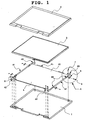
- Fig. 1 is an exploded perspective view for use in explaining a liquid crystal module mounting structure according to the first embodiment of the present invention.
- the mounting structure according to the first embodiment includes a rear case 1, a bracket 4, an LCD unit 3 and a front case 2.
- the bracket 4 is composed of a base plate 40, sidewall parts 41 on the opposite sides and two upper tabs 45.
- Each sidewall part 41 includes a lower tab 42, an upper tab 43 and a projection part 44 as an attachment part of a side fixing piece.
- a projection part 44 Provided between the base plate 40 and the projection part 44 is an opening part 44a so as to make the projection part be resilient.
- a screw hole having screw threads therein is formed.
- the upper tabs 45 are formed to uprise from the upper end of the base plate 40.
- a side fixing piece 5 whose section is substantially L-shaped is fixed to each projection part 44 by means of a screw 6.
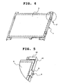
- Fig. 5 which is an expanded view of the part F of Fig. 4 as a perspective view of a state where the LCD unit 3 is attached to the bracket 4 and Fig. 7, a peripheral part of a display surface of the LCD unit 3 is firmly installed as a result of the pressing by the side fixing piece 5.
- the bracket 4 is screwed on the rear case 1 by screws 7 and 8 with the display surface held at an appropriate state by the lower tab 42 and the upper tab 43.
- the LCD unit 3 being incorporated into the bracket 4 is attached to the rear case 1.
- Fig. 6 is a plan view of the LCD unit 3 appropriately incorporated into the bracket 4.
- Figs. 7, 8, 9 and 10 are partial sectional views taken along the lines B-B, C-C, D-D and E-E indicated in Fig. 6, respectively.
- the side fixing piece 5 is screwed to the projection part 44 of the bracket 4 by means of the screw 6.
- the LCD unit 3 is firmly installed between the side fixing piece 5 and the base plate 40 of the bracket 4.
- the LCD unit 3 is fixed to the bracket 4 with its upper and lower and left and right sides held by the upper tab 45 (Fig. 8), the sidewall part 41 (Fig. 10) and the lower tab 42 (Fig. 9) uprising from the base plate 40.
- a cushion member 50 made of an extensible member e.g. rubber member
- provision of such a cushion member 50 as described above is not necessary.
- the LCD unit 3 When the LCD unit 3 is manufactured by a plurality of manufactures to slightly vary in size, in particular, it is possible that a spacing is generated between the side surface of the LCD unit 3 and the sidewall part 41 of the bracket 4, between the side surface of the LCD unit 3 and the upper tab 45 and between the side surface of the LCD unit 3 and the lower tab 42. In such a case, such a cushion member 50 as mentioned above will be provided at the spacing.
- the back side of the LCD unit 3 is directly attached on the base plate 40 of the bracket 4.
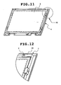
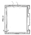
- Figs. 11 and 13 are a perspective view and a plan view showing a state where the bracket 4 with the LCD unit 3 incorporated therein is mounted on the rear case 1, respectively.
- Fig. 12 which is an expanded view of the part H of Fig. 11, the upper tab 43 of the bracket 4 is screwed to the rear case 1 by means of the screw 7.
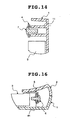
- Fig. 14 is a partial sectional view taken along the line G-G illustrated in Fig. 13.
- the rear case 1 includes a boss 11 having screw threads therein at the positions corresponding to the upper tab 43 of the bracket 4. As shown in the figure, screwing the screw 7 into the boss 11 through the hole of the upper tab 43 results in fixing the upper tab 43 to the boss 11.
- bosses similar to the boss 11 are provided in the plural (three) and as illustrated in Fig. 1, screwing the three screws 8 into the bosses through the holes of the lower tab 42 results in fixing the lower tab 42 to the rear case 1.
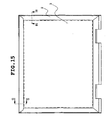
- Fig. 15 is a plan view showing a state where after the bracket 4 with the LCD unit 3 incorporated therein is mounted on the rear case 1, the front side is covered with the front case 2.
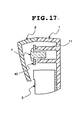
- Figs. 16 and 17 show partial sectional views taken along the lines B-B and G-G indicated in Fig. 15, respectively. As illustrated in Figs. 16 and 17, the side fixing piece 5, the projection part 44, the screw 6 (Fig. 16), the upper tab 43, the screw 7 and the boss 11 (Fig. 17) are covered by the front case 2.
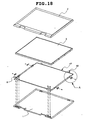
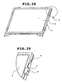
- Fig. 18 is an exploded perspective view for use in explaining the liquid crystal module mounting structure according to the second embodiment of the present invention.
- the second embodiment includes a new fixing structure in place of the upper tab 43, the boss 11 and the screw 7.
- the fixing structure according to the present embodiment will be applied.
- the bracket 4 includes, in place of the upper tab 43 and the upper tab 45 of the first embodiment, an upper wall part 47 uprising from the upper end of the bracket 4 and an upper tab 46 externally projecting from the upper wall part 47. Differently from the upper tab 43 of the first embodiment, the upper tab 46 has no hole for screwing.
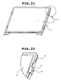
- Fig. 19 which is an expanded view of the part A of Fig. 18 and Fig. 22 which is an expanded view of the part F of Fig. 21 as a perspective view of a state where the LCD unit 3 is attached to the bracket 4, that the side fixing piece 5 is attached to each projection part 44 of the bracket 4 by means of the screw 6 is the same as that in the first embodiment.
- the bracket 4 is screwed to the rear case 1 with the display surface held at an appropriate state by the lower tab 42 and the upper tab 46.
- the LCD unit 3 being incorporated into the bracket 4 is mounted on the rear case 1.
- Fig. 23 is a plan view of the LCD unit 3 appropriately incorporated into the bracket 4.
- Figs. 24, 25, 26 and 27 are partial sectional views taken along the lines B-B, C-C, D-D and E-E illustrated in Fig. 23, respectively.
- the side fixing piece 5 is screwed to the projection part 44 of the bracket 4 by means of the screw 6.
- the LCD unit 3 is firmly installed between the side fixing piece 5 and the base plate 40 of the bracket 4.
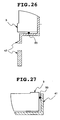
- the LCD unit 3 is incorporated into the bracket 4 with its upper and lower and left and right sides held by the upper wall part 47 (Fig. 25), the sidewall part 41 (Fig. 27) and the lower tab 42 (Fig. 26) uprising from the base plate 40.
- the cushion member 50 made of an extensible member (rubber member) is assumed to be provided therebetween as required.
- the cushion member 50 made of an extensible member (rubber member) is assumed to be provided therebetween as required.
- the LCD unit 3 When the LCD unit 3 is manufactured by a plurality of manufactures to slightly vary in size, in particular, it is possible that a spacing is generated between the side surface of the LCD unit 3 and the sidewall part 41 of the bracket 4, between the side surface of the LCD unit 3 and the upper tab 46 and between the side surface of the LCD unit 3 and the lower tab 42. In such a case, such a cushion member 50 as mentioned above will be provided at the spacing.
- the back side of the LCD unit 3 is directly attached on the base plate 40 of the bracket 4.
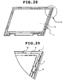
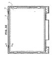
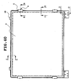
- Figs. 28 and 30 are a perspective view and a plan view showing a state where the bracket 4 with the LCD unit 3 incorporated therein is mounted on the rear case 1, respectively.
- Fig. 30 is a plan view of the LCD unit 3 and the bracket 4 mounted on the rear case 1.
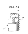
- Fig. 31 is a. partial sectional view taken along the line G-G shown in Fig. 30.
- the rear case 1 has a holder part 12 whose section is L-shaped provided at a position corresponding to the upper tab 46 of the bracket 4.
- the holder part 12 is integrally formed to uprise from the bottom surface of the rear case 1 at a position spaced apart from the upper sidewall of the rear case 1 and is formed into a pocket whose section is L-shaped allowing insertion of the upper tab 46 of the bracket 4.
- the width of the holder part 12 is approximately equal to that of the upper tab 46.
- the upper tab 46 and the holder part 12 are neither screwed nor adhered as mentioned above.
- the upper tab 46 is attached only through insertion into the holder part 12.
- Fig. 32 is a plan view showing a state where after the bracket 4 with the LCD unit 3 incorporated therein is mounted on the rear case 1, the front side is covered with the front case 2.
- Figs. 33 and 34 show partial sectional views taken along the lines B-B and G-G indicated in Fig. 32, respectively. As illustrated in Figs. 33 and 34, the side fixing piece 5, the projection part 44, the screw 6 (Fig. 33), the upper tab 46, and the holder part 12 (Fig. 34) are covered by the front case 2.
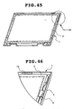
- Fig. 35 is an exploded perspective view for use in explaining the liquid crystal module mounting structure according to the third embodiment of the present invention.
- the third embodiment is a modification of the above-described structure according to the second embodiment and while the L-shaped holder part 12 in the second embodiment is formed to uprise from the bottom part of the rear case 1, a holder part 13 in the present embodiment is formed directly at the sidewall part of the rear case 1.
- a holder part 13 on the sidewall of the rear case 1 enables the upper tab 46 of the bracket 4 to be inserted and held even when a spacing between the LCD unit 3 and the sidewall of the rear case 1 is too small on the upper side to form the L-shaped holder part 12.
- the rear case 1 includes the holder part 13 in place of the L-shaped holder part 12 shown in the second embodiment.
- the holder part 13 is integrally formed on the upper sidewall of the rear case 1 and formed into a pocket whose section is L-shaped allowing insertion of the upper tab 46 of the bracket 4.
- the width of the holder part 13 is approximately equal to that of the upper tab 46.
- the upper tab 46 of the bracket 4 is inserted into the holder part 13.
- the bracket 4 includes, in place of the upper tab 43 and the upper tab 45 of the first embodiment, the upper wall part 47 uprising from the upper end of the bracket 4 and the upper tab 46. Differently from the upper tab 43 of the first embodiment, the upper tab 46 has no hole for screwing.
- Fig. 36 which is an expanded view of the part A of Fig. 35
- the side fixing piece 5 is attached to each projection part 44 of the bracket 4 by means of the screw 6.
- Fig. 39 which is an expanded view of the part F of Fig. 38 as a perspective view of a state where the LCD unit 3 is attached to the bracket 4, the display surface of the LCD unit 3 is firmly installed by the side fixing piece 5.
- the bracket 4 is attached to the rear case 1 with the display surface held at an appropriate state by the lower tab 42 and the upper tab 46. As illustrated in the figure, the LCD unit 3 being incorporated into the bracket 4 is mounted on the rear case 1.
- Fig. 40 is a plan view of the LCD unit 3 appropriately incorporated into the bracket 4.
- Figs. 41, 42, 43 and 44 are partial sectional views taken along the lines B-B, C-C, D-D and E-E illustrated in Fig. 40, respectively.
- the side fixing piece 5 is screwed to the projection part 44 of the bracket 4 by means of the screw 6.
- the LCD unit 3 is firmly installed between the side fixing piece 5 and the base plate 40 of the bracket 4.
- the LCD unit 3 is incorporated into the bracket 4 with its upper and lower and left and right sides held by the upper wall part 47 (Fig. 42), the sidewall part 41 (Fig. 44) and the lower tab 42 (Fig. 43) uprising from the base plate 40. That at a spacing between the LCD unit 3 and these parts, the cushion member 50 is provided is the same as that in the above first and second embodiments.
- Figs. 45 and 47 are a perspective view and a plan view showing a state where the bracket 4 with the LCD unit 3 incorporated therein is mounted on the rear case 1, respectively.
- Fig. 47 is a plan view of the LCD unit 3 and the bracket 4 mounted on the rear case 1.
- Fig. 48 is a partial sectional view taken along the line G-G shown in Fig. 47. With reference to Fig. 48, insertion of the upper tab 46 of the bracket 4 into the above-described holder part 13 of the rear case 1 results in the upper part of the bracket 4 being held to the rear case 1.
- the upper tab 46 and the holder part 13 are neither screwed nor adhered as mentioned above.
- the upper tab 46 is attached only through insertion into the holder part 13.
- Fig. 49 is a plan view showing a state where after the bracket 4 with the LCD unit 3 incorporated therein is mounted on the rear case 1, the front side is covered with the front case 2.
- Figs. 50 and 51 show partial sectional views taken along the lines B-B and G-G indicated in Fig. 49, respectively. As illustrated in Figs. 50 and 51, the side fixing piece 5, the projection part 44, the screw 6 (Fig. 50), the upper tab 46, and the holder part 13 (Fig. 51) are covered by the front case 2.
- the liquid.crystal module mounting structure of the present invention has the following effects.
Landscapes
- Physics & Mathematics (AREA)
- Nonlinear Science (AREA)
- Mathematical Physics (AREA)
- Chemical & Material Sciences (AREA)
- Crystallography & Structural Chemistry (AREA)
- General Physics & Mathematics (AREA)
- Optics & Photonics (AREA)
- Devices For Indicating Variable Information By Combining Individual Elements (AREA)
- Liquid Crystal (AREA)
Description
- The present invention relates to a mounting structure for a liquid crystal module for use in a portable information processor etc. and, more particularly, to a liquid crystal module mounting structure enabling various kinds of liquid crystal modules to be mounted in a bracket with ease.
- It is a common practice for conventional portable information processors such as notebook-sized personal computers to adopt a liquid crystal module (hereinafter referred to as a LCD) for use in a display unit. In addition, various kinds of LCDs manufactured by a plurality of manufactures are often packaged in one portable information processor.
- In conventional LCD mounting, most frequently used is a system called "side-mount system" of directly fixing a screw hole provided on a side surface of an LCD and a bracket by means of a screw.
- Mounting various kinds of LCDs in one kind of bracket as described above, however, requires provision of a plurality of holes in the bracket corresponding to attaching holes of each LCD in advance or preparation of as many attachment parts for connecting the LCDs and the bracket as the number of kinds of the LCDs.
- As mentioned above, among conventional LCD mounting structures, the system in which a plurality of attaching holes are provided for each LCD has problems in strength and appearances because numerous attaching holes are visible outside. The system using attachment parts also has a shortcoming that attachment parts should be prepared as many as the number of kinds of LCDs. Prior art mounting structures for LCDs are known from JP-A-9-288 455 and JP-A-11-006 998.
- An object of the present invention as defined by the claims is to eliminate the above-described shortcomings of conventional art and provide a liquid crystal module mounting structure enabling various kinds of different liquid crystal modules to be mounted in a bracket with ease without the need of neither provision of a plurality of holes corresponding to attaching holes of liquid crystal modules in advance nor preparation of attachment parts for each liquid crystal module.
- The present invention will be understood more fully from the detailed description given herebelow and from the accompanying drawings of the preferred embodiments of the invention, which, however, should not be taken to be limitative to the invention, but are for explanation and understanding only.
- In the drawings:
- Fig. 1 is an exploded perspective view of a liquid crystal module mounting structure according to a first embodiment of the present invention;
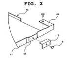
- Fig. 2 is a partial expanded view of a part A of Fig. 1;
- Fig. 3 is a view showing a plane surface and a side surface of a bracket of the first embodiment;
- Fig. 4 is a perspective view showing a state where an LCD unit of the first embodiment is housed in the bracket;
- Fig. 5 is a partial expanded view of a part F of Fig. 4;
- Fig. 6 is a plan view showing a state where the LCD unit of the first embodiment is housed in the bracket;
- Fig. 7 is an expanded sectional view of a part taken along the line B-B of Fig. 6;
- Fig. 8 is an expanded sectional view of a part taken along the line C-C of Fig. 6;
- Fig. 9 is an expanded sectional view of a part taken along the line D-D of Fig. 6;
- Fig. 10 is an expanded sectional view of a part taken along the line E-E of Fig. 6;
- Fig. 11 is a perspective view showing a state where the LCD unit and the bracket of the first embodiment are incorporated into a rear case;
- Fig. 12 is a partial expanded view of a part H of Fig. 11;
- Fig. 13 is a plan view showing a state where the LCD unit and the bracket of the first embodiment are incorporated into the rear case;
- Fig. 14 is an expanded sectional view of a part taken along the line G-G of Fig. 13;
- Fig. 15 is a plan view of a state where a front case of the first embodiment is mounted;
- Fig. 16 is an expanded sectional view of a part taken along the line B-B of Fig. 15;
- Fig. 17 is an expanded sectional view of a part taken along the line of G-G of Fig. 15;
- Fig. 18 is an exploded perspective view of a liquid crystal module mounting structure according to a second embodiment of the present invention;
- Fig. 19 is a partial expanded view of a part A of Fig. 18;
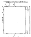
- Fig. 20 is a view showing a plane surface and a side surface of a bracket of the second embodiment;
- Fig. 21 is a perspective view showing a state where an LCD unit of the second embodiment is housed in the bracket;
- Fig. 22 is a partial expanded view of a part F of Fig. 21;
- Fig. 23 is a plan view showing a state where the LCD unit of the second embodiment is housed in the bracket;
- Fig. 24 is an expanded sectional view of a part taken along the line B-B of Fig. 23;
- Fig. 25 is an expanded sectional view of a part taken along the line C-C of Fig. 23;
- Fig. 26 is an expanded sectional view of a part taken along the line D-D of Fig. 23;
- Fig. 27 is an expanded sectional view of a part taken along the line E-E of Fig. 23;
- Fig. 28 is a perspective view showing a state where the LCD unit and the bracket of the second embodiment are incorporated into a rear case;
- Fig. 29 is a partial expanded view of a part H of Fig. 28;
- Fig. 30 is a plan view showing a state where the LCD unit and the bracket of the second embodiment are incorporated into the rear case;
- Fig. 31 is an expanded sectional view of a part taken along the line G-G of Fig. 30;
- Fig. 32 is a plan view of a state where a front case of the second embodiment is mounted;
- Fig. 33 is an expanded sectional view of a part taken along the line B-B of Fig. 32;
- Fig. 34 is an expanded sectional view of a part taken along the line G-G of Fig. 32;
- Fig. 35 is an exploded perspective view of a liquid crystal module mounting structure according to a third embodiment of the present invention;
- Fig. 36 is a partial expanded view of a part A of Fig. 35;
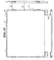
- Fig. 37 is a view showing a plane surface and a side surface of a bracket of the third embodiment;
- Fig. 38 is a perspective view showing a state where an LCD unit of the third embodiment is housed in the bracket;
- Fig. 39 is a partial expanded view of a part F of Fig. 38;
- Fig. 40 is a plan view showing a state where the LCD unit of the third embodiment is housed in the bracket;
- Fig. 41 is an expanded sectional view of a part taken along the line B-B of Fig. 40;
- Fig. 42 is an expanded sectional view of a part taken along the line C-C of Fig. 40;
- Fig. 43 is an expanded sectional view of a part taken along the line D-D of Fig. 40;
- Fig. 44 is an expanded sectional view of a part taken along the line E-E of Fig. 40;
- Fig. 45 is a perspective view showing a state where the LCD unit and the bracket of the third embodiment are incorporated into a rear case;
- Fig. 46 is a partial expanded view of a part H of Fig. 45;
- Fig. 47 is a plan view showing a state where the LCD unit and the bracket of the third embodiment are incorporated into the rear case;
- Fig. 48 is an expanded sectional view of a part taken along the line G-G of Fig. 47;
- Fig. 49 is a plan view of a state where a front case of the third embodiment is mounted;
- Fig. 50 is an expanded sectional view of a part taken along the line B-B of Fig. 49; and
- Fig. 51 is an expanded sectional view of a part taken along the line G-G of Fig. 49.
- The preferred embodiments of the present invention will be discussed hereinafter in detail with reference to the accompanying drawings. In the following description, numerous specific details are set forth in order to provide a thorough understanding of the present invention. It will be obvious, however, to those skilled in the art that the present invention may be practiced without these specific details. In other instances, well-known structures are not shown in detail in order to unnecessary obscure the present invention.
- In the following, embodiments of the present invention will be described in detail with reference to the drawings. Fig. 1 is an exploded perspective view for use in explaining a liquid crystal module mounting structure according to the first embodiment of the present invention.
- With reference to Fig. 1, the mounting structure according to the first embodiment includes a
rear case 1, abracket 4, anLCD unit 3 and afront case 2. With reference to Figs. 1 and 3, thebracket 4 is composed of abase plate 40,sidewall parts 41 on the opposite sides and twoupper tabs 45. - Each
sidewall part 41 includes alower tab 42, anupper tab 43 and aprojection part 44 as an attachment part of a side fixing piece. Provided between thebase plate 40 and theprojection part 44 is anopening part 44a so as to make the projection part be resilient. In eachprojection part 44, a screw hole having screw threads therein is formed. - The
upper tabs 45 are formed to uprise from the upper end of thebase plate 40. - With reference to Fig. 2 which is an expanded view of the part A of Fig. 1, a
side fixing piece 5 whose section is substantially L-shaped is fixed to eachprojection part 44 by means of ascrew 6. As shown in Fig. 5 which is an expanded view of the part F of Fig. 4 as a perspective view of a state where theLCD unit 3 is attached to thebracket 4 and Fig. 7, a peripheral part of a display surface of theLCD unit 3 is firmly installed as a result of the pressing by theside fixing piece 5. - With reference to Fig. 1, the
bracket 4 is screwed on therear case 1 byscrews lower tab 42 and theupper tab 43. As illustrated in the figure, theLCD unit 3 being incorporated into thebracket 4 is attached to therear case 1. - Fig. 6 is a plan view of the
LCD unit 3 appropriately incorporated into thebracket 4. Figs. 7, 8, 9 and 10 are partial sectional views taken along the lines B-B, C-C, D-D and E-E indicated in Fig. 6, respectively. - With reference to Fig. 7, the
side fixing piece 5 is screwed to theprojection part 44 of thebracket 4 by means of thescrew 6. As a result, theLCD unit 3 is firmly installed between theside fixing piece 5 and thebase plate 40 of thebracket 4. - With reference to Figs. 8, 9 and 10, the
LCD unit 3 is fixed to thebracket 4 with its upper and lower and left and right sides held by the upper tab 45 (Fig. 8), the sidewall part 41 (Fig. 10) and the lower tab 42 (Fig. 9) uprising from thebase plate 40. When a spacing is generated between theLCD unit 3 and these parts, acushion member 50 made of an extensible member (e.g. rubber member) is assumed to be provided therebetween as required. When there is no spacing between theLCD unit 3 and these parts, provision of such acushion member 50 as described above is not necessary. - When the
LCD unit 3 is manufactured by a plurality of manufactures to slightly vary in size, in particular, it is possible that a spacing is generated between the side surface of theLCD unit 3 and thesidewall part 41 of thebracket 4, between the side surface of theLCD unit 3 and theupper tab 45 and between the side surface of theLCD unit 3 and thelower tab 42. In such a case, such acushion member 50 as mentioned above will be provided at the spacing. The back side of theLCD unit 3 is directly attached on thebase plate 40 of thebracket 4. - As described above, the
LCD unit 3 being incorporated into thebracket 4 is mounted on therear case 1. Figs. 11 and 13 are a perspective view and a plan view showing a state where thebracket 4 with theLCD unit 3 incorporated therein is mounted on therear case 1, respectively. - With reference to Fig. 12 which is an expanded view of the part H of Fig. 11, the
upper tab 43 of thebracket 4 is screwed to therear case 1 by means of thescrew 7. Fig. 14 is a partial sectional view taken along the line G-G illustrated in Fig. 13. As illustrated in Fig. 14, therear case 1 includes aboss 11 having screw threads therein at the positions corresponding to theupper tab 43 of thebracket 4. As shown in the figure, screwing thescrew 7 into theboss 11 through the hole of theupper tab 43 results in fixing theupper tab 43 to theboss 11. - Also at the positions in the
rear case 1 corresponding to the holes (three) of thelower tab 42 of thebracket 4, bosses similar to theboss 11 are provided in the plural (three) and as illustrated in Fig. 1, screwing the threescrews 8 into the bosses through the holes of thelower tab 42 results in fixing thelower tab 42 to therear case 1. - Fig. 15 is a plan view showing a state where after the
bracket 4 with theLCD unit 3 incorporated therein is mounted on therear case 1, the front side is covered with thefront case 2. Figs. 16 and 17 show partial sectional views taken along the lines B-B and G-G indicated in Fig. 15, respectively. As illustrated in Figs. 16 and 17, theside fixing piece 5, theprojection part 44, the screw 6 (Fig. 16), theupper tab 43, thescrew 7 and the boss 11 (Fig. 17) are covered by thefront case 2. - Next, a liquid crystal module mounting structure according to the second embodiment of the present invention will be described. Fig. 18 is an exploded perspective view for use in explaining the liquid crystal module mounting structure according to the second embodiment of the present invention.
- The difference from the above-described first embodiment is that the second embodiment includes a new fixing structure in place of the
upper tab 43, theboss 11 and thescrew 7. In a case where a spacing between theLCD unit 3 and therear case 1 is too small on the upper side to have theboss 11 for screwing by thescrew 7 on therear case 1, the fixing structure according to the present embodiment will be applied. - With reference to Figs. 18, 19 and 20, the
bracket 4 includes, in place of theupper tab 43 and theupper tab 45 of the first embodiment, anupper wall part 47 uprising from the upper end of thebracket 4 and anupper tab 46 externally projecting from theupper wall part 47. Differently from theupper tab 43 of the first embodiment, theupper tab 46 has no hole for screwing. - With reference to Fig. 19 which is an expanded view of the part A of Fig. 18 and Fig. 22 which is an expanded view of the part F of Fig. 21 as a perspective view of a state where the
LCD unit 3 is attached to thebracket 4, that theside fixing piece 5 is attached to eachprojection part 44 of thebracket 4 by means of thescrew 6 is the same as that in the first embodiment. - With reference to Fig. 18, the
bracket 4 is screwed to therear case 1 with the display surface held at an appropriate state by thelower tab 42 and theupper tab 46. As illustrated in the figure, theLCD unit 3 being incorporated into thebracket 4 is mounted on therear case 1. - Fig. 23 is a plan view of the
LCD unit 3 appropriately incorporated into thebracket 4. Figs. 24, 25, 26 and 27 are partial sectional views taken along the lines B-B, C-C, D-D and E-E illustrated in Fig. 23, respectively. - With reference to Fig. 24, the
side fixing piece 5 is screwed to theprojection part 44 of thebracket 4 by means of thescrew 6. As a result, theLCD unit 3 is firmly installed between theside fixing piece 5 and thebase plate 40 of thebracket 4. - With reference to Figs. 25, 26 and 27, the
LCD unit 3 is incorporated into thebracket 4 with its upper and lower and left and right sides held by the upper wall part 47 (Fig. 25), the sidewall part 41 (Fig. 27) and the lower tab 42 (Fig. 26) uprising from thebase plate 40. - When a spacing is generated between the
LCD unit 3 and these parts, thecushion member 50 made of an extensible member (rubber member) is assumed to be provided therebetween as required. When there is no spacing between theLCD unit 3 and these parts, provision of such acushion member 50 as described above is not necessary. - When the
LCD unit 3 is manufactured by a plurality of manufactures to slightly vary in size, in particular, it is possible that a spacing is generated between the side surface of theLCD unit 3 and thesidewall part 41 of thebracket 4, between the side surface of theLCD unit 3 and theupper tab 46 and between the side surface of theLCD unit 3 and thelower tab 42. In such a case, such acushion member 50 as mentioned above will be provided at the spacing. The back side of theLCD unit 3 is directly attached on thebase plate 40 of thebracket 4. - As described above, the
LCD unit 3 being incorporated into thebracket 4 is mounted on therear case 1. Figs. 28 and 30 are a perspective view and a plan view showing a state where thebracket 4 with theLCD unit 3 incorporated therein is mounted on therear case 1, respectively. - Fig. 30 is a plan view of the
LCD unit 3 and thebracket 4 mounted on therear case 1. Fig. 31 is a. partial sectional view taken along the line G-G shown in Fig. 30. With reference to Fig. 31, therear case 1 has aholder part 12 whose section is L-shaped provided at a position corresponding to theupper tab 46 of thebracket 4. - The
holder part 12 is integrally formed to uprise from the bottom surface of therear case 1 at a position spaced apart from the upper sidewall of therear case 1 and is formed into a pocket whose section is L-shaped allowing insertion of theupper tab 46 of thebracket 4. The width of theholder part 12 is approximately equal to that of theupper tab 46. - Insertion of the
upper tab 46 of thebracket 4 into theholder part 12 results in the upper part of thebracket 4 being held to therear case 1. - In addition, that in the
rear case 1, thelower tab 42 of thebracket 4 is screwed to therear case 1 by thescrew 8 is the same as that in the first embodiment. - In the second embodiment, the
upper tab 46 and theholder part 12 are neither screwed nor adhered as mentioned above. Theupper tab 46 is attached only through insertion into theholder part 12. - Fig. 32 is a plan view showing a state where after the
bracket 4 with theLCD unit 3 incorporated therein is mounted on therear case 1, the front side is covered with thefront case 2. Figs. 33 and 34 show partial sectional views taken along the lines B-B and G-G indicated in Fig. 32, respectively. As illustrated in Figs. 33 and 34, theside fixing piece 5, theprojection part 44, the screw 6 (Fig. 33), theupper tab 46, and the holder part 12 (Fig. 34) are covered by thefront case 2. - Next, a liquid crystal module mounting structure according to the third embodiment of the present invention will be described. Fig. 35 is an exploded perspective view for use in explaining the liquid crystal module mounting structure according to the third embodiment of the present invention.
- The third embodiment is a modification of the above-described structure according to the second embodiment and while the L-shaped
holder part 12 in the second embodiment is formed to uprise from the bottom part of therear case 1, aholder part 13 in the present embodiment is formed directly at the sidewall part of therear case 1. Thus formedholder part 13 on the sidewall of therear case 1 enables theupper tab 46 of thebracket 4 to be inserted and held even when a spacing between theLCD unit 3 and the sidewall of therear case 1 is too small on the upper side to form the L-shapedholder part 12. - With reference to Fig. 48, the
rear case 1 includes theholder part 13 in place of the L-shapedholder part 12 shown in the second embodiment. Theholder part 13 is integrally formed on the upper sidewall of therear case 1 and formed into a pocket whose section is L-shaped allowing insertion of theupper tab 46 of thebracket 4. The width of theholder part 13 is approximately equal to that of theupper tab 46. - For attaching the
bracket 4 to therear case 1, theupper tab 46 of thebracket 4 is inserted into theholder part 13. - With reference to Figs. 35, 36 and 37, the
bracket 4 includes, in place of theupper tab 43 and theupper tab 45 of the first embodiment, theupper wall part 47 uprising from the upper end of thebracket 4 and theupper tab 46. Differently from theupper tab 43 of the first embodiment, theupper tab 46 has no hole for screwing. - With reference to Fig. 36 which is an expanded view of the part A of Fig. 35 , the
side fixing piece 5 is attached to eachprojection part 44 of thebracket 4 by means of thescrew 6. Also, as illustrated in Fig. 39 which is an expanded view of the part F of Fig. 38 as a perspective view of a state where theLCD unit 3 is attached to thebracket 4, the display surface of theLCD unit 3 is firmly installed by theside fixing piece 5. - With reference to Fig. 35, the
bracket 4 is attached to therear case 1 with the display surface held at an appropriate state by thelower tab 42 and theupper tab 46. As illustrated in the figure, theLCD unit 3 being incorporated into thebracket 4 is mounted on therear case 1. - Fig. 40 is a plan view of the
LCD unit 3 appropriately incorporated into thebracket 4. Figs. 41, 42, 43 and 44 are partial sectional views taken along the lines B-B, C-C, D-D and E-E illustrated in Fig. 40, respectively. - With reference to Fig. 41, the
side fixing piece 5 is screwed to theprojection part 44 of thebracket 4 by means of thescrew 6. As a result, theLCD unit 3 is firmly installed between theside fixing piece 5 and thebase plate 40 of thebracket 4. - With reference to Figs. 42, 43 and 44, the
LCD unit 3 is incorporated into thebracket 4 with its upper and lower and left and right sides held by the upper wall part 47 (Fig. 42), the sidewall part 41 (Fig. 44) and the lower tab 42 (Fig. 43) uprising from thebase plate 40. That at a spacing between theLCD unit 3 and these parts, thecushion member 50 is provided is the same as that in the above first and second embodiments. - As described above, the
LCD unit 3 being incorporated into thebracket 4 is mounted on therear case 1. Figs. 45 and 47 are a perspective view and a plan view showing a state where thebracket 4 with theLCD unit 3 incorporated therein is mounted on therear case 1, respectively. - Fig. 47 is a plan view of the
LCD unit 3 and thebracket 4 mounted on therear case 1. Fig. 48 is a partial sectional view taken along the line G-G shown in Fig. 47. With reference to Fig. 48, insertion of theupper tab 46 of thebracket 4 into the above-describedholder part 13 of therear case 1 results in the upper part of thebracket 4 being held to therear case 1. - In addition, that in the
rear case 1, thelower tab 42 of thebracket 4 is screwed to therear case 1 by thescrew 8 the same as that in the first and second embodiments. - In the third embodiment, the
upper tab 46 and theholder part 13 are neither screwed nor adhered as mentioned above. Theupper tab 46 is attached only through insertion into theholder part 13. - Fig. 49 is a plan view showing a state where after the
bracket 4 with theLCD unit 3 incorporated therein is mounted on therear case 1, the front side is covered with thefront case 2. Figs. 50 and 51 show partial sectional views taken along the lines B-B and G-G indicated in Fig. 49, respectively. As illustrated in Figs. 50 and 51, theside fixing piece 5, theprojection part 44, the screw 6 (Fig. 50), theupper tab 46, and the holder part 13 (Fig. 51) are covered by thefront case 2. - As described in the foregoing, the liquid.crystal module mounting structure of the present invention has the following effects.
- First, attaching L-shaped fixing pieces at several positions of a bracket for housing a liquid crystal module enables many kinds of liquid crystal modules to be mounted on one kind of bracket with ease. The reason is that because fixing a screen peripheral part of the liquid crystal module through the pressing by a fixing piece is not dependent on a kind of liquid crystal module.
- Secondly, because it is necessary neither to provide numerous holes on a bracket corresponding to many kinds of liquid crystal modules nor to prepare as many attachment parts for connecting a liquid crystal module and the bracket as the number of kinds of liquid crystal modules, the problem in strength caused by the provision of numerous holes is resolved and cost reduction is realized as well.
Claims (7)
- A mounting structure for a liquid crystal module, said structure comprising a box-formed bracket (4) for housing a liquid crystal module unit (3), wherein
an attachment part (44) is provided at a sidewall portion (41) of said bracket (4),
said liquid crystal module unit (3) is held by the pressing of a peripheral portion of said liquid crystal module unit from the screen side by a substantially L-shaped fixing piece (5) attached to said attachment part (44), and
said attachment part (44) is formed as an external projection part of the sidewall portion (41) of said bracket (4) to have resiliency. - The mounting structure as set forth in claim 1, wherein
said attachment part (44) is provided at four positions in the vicinity of the four corners of said bracket (4). - The mounting structure as set forth in claim 1 or 2, wherein
a screw hole is provided in said attachment part (44) to enable said fixing piece (5) to be attached to said attachment part (44) by means of a screw (6). - The mounting structure as set forth in claim 1, 2, or 3, further comprising a box-formed case (1) into which said bracket (4) is incorporated, wherein
in the vicinity of the four corners of said bracket (4), a tab (42, 43) is provided for screwing to said case (1),
at a position on the side of said case (1) corresponding to said tab (42, 43), a boss (11) having a screw hole is provided, and
said bracket (4) which houses said liquid crystal module unit (3) is incorporated into said case (1) by screwing said tab (42, 43) to said boss (11). - The mounting structure as set forth in claim 1, 2, or 3, further comprising a box-formed case (1) into which said bracket (4) is incorporated, wherein
on one of an upper portion and a lower portion of said bracket (4), a first tab (46) externally projecting from said sidewall is provided and on the other a second tab (42) is provided for screwing to said case (1)
at a position of said case (1) corresponding to said first tab (46), a holder part (12) is provided for allowing said first tab (46) to be inserted and held and at a said first tab (46) be inserted and held and at a position of said case (1) corresponding to said second tab (42), a boss (11) having a screw hole is provided, and
said bracket (4) housing said liquid crystal module unit (3) is incorporated into said case (1) by inserting said first tab (46) into said holder part (12) and screwing said second tab (42) to said boss (11). - The mounting structure as set forth in claim 5, wherein
said holder part (12) of said case (1) is formed into a pocket whose section is L-shaped at a position inwardly apart from the sidewall of said case (1). - The mounting structure as set forth in claim 5, wherein
said holder part (12) of said case (1) is formed into a pocket whose section is L-shaped at the sidewall portion of said case (1).
Applications Claiming Priority (2)
| Application Number | Priority Date | Filing Date | Title |
|---|---|---|---|
| JP20189599 | 1999-07-15 | ||
| JP20189599A JP3372905B2 (en) | 1999-07-15 | 1999-07-15 | LCD module mounting structure |
Publications (3)
| Publication Number | Publication Date |
|---|---|
| EP1069459A2 EP1069459A2 (en) | 2001-01-17 |
| EP1069459A3 EP1069459A3 (en) | 2004-08-11 |
| EP1069459B1 true EP1069459B1 (en) | 2007-02-14 |
Family
ID=16448612
Family Applications (1)
| Application Number | Title | Priority Date | Filing Date |
|---|---|---|---|
| EP00115337A Expired - Lifetime EP1069459B1 (en) | 1999-07-15 | 2000-07-14 | Mounting structure for liquid crystal modules |
Country Status (7)
| Country | Link |
|---|---|
| US (1) | US6525790B1 (en) |
| EP (1) | EP1069459B1 (en) |
| JP (1) | JP3372905B2 (en) |
| AU (1) | AU779441B2 (en) |
| CA (1) | CA2313726C (en) |
| DE (1) | DE60033343T2 (en) |
| TW (1) | TW589488B (en) |
Families Citing this family (42)
| Publication number | Priority date | Publication date | Assignee | Title |
|---|---|---|---|---|
| KR100508003B1 (en) * | 1998-11-11 | 2005-11-21 | 엘지.필립스 엘시디 주식회사 | How to combine a portable computer with its flat panel display |
| JP3847532B2 (en) * | 2000-07-05 | 2006-11-22 | 株式会社日立製作所 | Liquid crystal module and liquid crystal monitor equipped with this liquid crystal module |
| FR2812112B1 (en) * | 2000-07-21 | 2003-01-31 | Thomson Csf | DISPLAY DEVICE WITH DISPLAY CELL |
| TW548479B (en) * | 2001-02-27 | 2003-08-21 | Matsushita Electric Industrial Co Ltd | Display device, display panel for the device, and the manufacturing method thereof |
| TWI298831B (en) | 2001-07-10 | 2008-07-11 | Fujitsu Ltd | Plane unit structure, portable computer and display unit(1) |
| JP4593604B2 (en) * | 2001-07-10 | 2010-12-08 | 富士通株式会社 | Planar unit structure |
| JP2003029241A (en) * | 2001-07-17 | 2003-01-29 | Sony Corp | Liquid crystal display device and information processing device |
| US7002792B2 (en) | 2002-04-04 | 2006-02-21 | Lg Electronics Inc. | Structure for mounting flat display module and method thereof |
| KR100468968B1 (en) * | 2002-04-04 | 2005-01-29 | 엘지전자 주식회사 | Display unit for notebook computer |
| JP4225748B2 (en) * | 2002-07-31 | 2009-02-18 | 富士通株式会社 | Display device |
| KR100493676B1 (en) * | 2002-10-11 | 2005-06-02 | 엘지전자 주식회사 | Portable computer system and its assembly method |
| KR100934250B1 (en) | 2002-12-30 | 2009-12-28 | 엘지디스플레이 주식회사 | Flat Panel Display Module |
| JP3974046B2 (en) * | 2003-02-04 | 2007-09-12 | 富士フイルム株式会社 | Display positioning mechanism |
| JP2005173509A (en) | 2003-12-15 | 2005-06-30 | Fujitsu Ltd | Electronic equipment |
| KR101213933B1 (en) * | 2004-05-31 | 2013-01-09 | 엘지디스플레이 주식회사 | Module for liquid crystal display device |
| JP4176695B2 (en) * | 2004-09-27 | 2008-11-05 | 株式会社東芝 | Liquid crystal display device and information terminal |
| US20060138296A1 (en) * | 2004-12-23 | 2006-06-29 | Deluga Ronald E | Display hold-down systems and methods |
| US7403377B2 (en) * | 2005-01-20 | 2008-07-22 | Hewlett-Packard Development Company, L.P. | Method of manufacture and an enclosure for a display for an electronic device |
| USD542295S1 (en) * | 2005-05-02 | 2007-05-08 | Sony Corporation | Fixing bar for monitor or television |
| CN2909316Y (en) * | 2006-04-28 | 2007-06-06 | 鸿富锦精密工业(深圳)有限公司 | Liquid crystal display |
| JP2007328613A (en) * | 2006-06-08 | 2007-12-20 | Toshiba Corp | Electronics |
| US20080016742A1 (en) * | 2006-06-09 | 2008-01-24 | Great Sun Tech Corp. | Photo frame structure |
| KR100838879B1 (en) | 2006-09-21 | 2008-06-16 | 엘지전자 주식회사 | Frames for Flat Panel Display Devices and Flat Panel Display Devices |
| JP2008281644A (en) * | 2007-05-08 | 2008-11-20 | Toshiba Corp | Support structure for display device and electronic device |
| CN201035465Y (en) * | 2007-09-12 | 2008-03-12 | 联想(北京)有限公司 | Notebook computer screen and notebook computer |
| JP5007638B2 (en) * | 2007-09-26 | 2012-08-22 | 富士通株式会社 | Electronics |
| TWI463872B (en) * | 2008-12-05 | 2014-12-01 | Compal Electronics Inc | Display module |
| KR101318757B1 (en) * | 2009-06-24 | 2013-10-16 | 엘지디스플레이 주식회사 | Liquid crystal display |
| CN101998783A (en) * | 2009-08-18 | 2011-03-30 | 深圳富泰宏精密工业有限公司 | Shell |
| CN102375483B (en) * | 2010-08-18 | 2014-04-16 | 富泰华工业(深圳)有限公司 | Fixing mechanism and electronic device using same |
| TWI446312B (en) * | 2010-09-10 | 2014-07-21 | Au Optronics Corp | Display device |
| CN102005159A (en) * | 2010-09-21 | 2011-04-06 | 友达光电股份有限公司 | Display device |
| CN102591042A (en) * | 2011-01-07 | 2012-07-18 | 康准电子科技(昆山)有限公司 | Display |
| JP2013025192A (en) * | 2011-07-22 | 2013-02-04 | Fujitsu Ltd | Display device and electronic instrument |
| TWI526074B (en) * | 2011-09-26 | 2016-03-11 | 仁寶電腦工業股份有限公司 | Display and assembling method thereof |
| JP5812902B2 (en) * | 2012-03-08 | 2015-11-17 | 三菱電機株式会社 | Display device |
| TW201340837A (en) * | 2012-03-28 | 2013-10-01 | Pegatron Corp | Display apparatus with detachable cover |
| TW201637543A (en) * | 2015-04-15 | 2016-10-16 | 鴻海精密工業股份有限公司 | Display device |
| JP6643723B2 (en) * | 2017-01-05 | 2020-02-12 | 富士通クライアントコンピューティング株式会社 | Information processing terminal and hinge unit |
| USD1020452S1 (en) | 2021-06-09 | 2024-04-02 | Nicholas Michael Hayes | Display case |
| USD1109804S1 (en) | 2024-07-15 | 2026-01-20 | Nicholas M Hayes | Video frame |
| USD1109735S1 (en) | 2024-07-15 | 2026-01-20 | Nicholas M Hayes | Video frame |
Family Cites Families (7)
| Publication number | Priority date | Publication date | Assignee | Title |
|---|---|---|---|---|
| JPH0347586A (en) | 1989-07-12 | 1991-02-28 | Ichikawa Gosei Kagaku Kk | Slime control agent |
| JPH04291319A (en) | 1991-03-20 | 1992-10-15 | Hitachi Ltd | small lcd module |
| JP2885693B2 (en) * | 1996-04-23 | 1999-04-26 | 静岡日本電気株式会社 | LCD holding structure for small electronic devices |
| JPH10319376A (en) | 1997-05-23 | 1998-12-04 | Matsushita Electric Ind Co Ltd | Liquid crystal display |
| JPH116998A (en) * | 1997-06-09 | 1999-01-12 | Internatl Business Mach Corp <Ibm> | Liquid crystal panel and liquid crystal display device |
| KR100258839B1 (en) * | 1998-01-24 | 2000-06-15 | 윤종용 | Lcd module |
| US6330148B1 (en) * | 1999-01-13 | 2001-12-11 | Lg. Philips Lcd Co., Ltd. | Flat panel display module for computer |
-
1999
- 1999-07-15 JP JP20189599A patent/JP3372905B2/en not_active Expired - Fee Related
-
2000
- 2000-07-11 CA CA002313726A patent/CA2313726C/en not_active Expired - Fee Related
- 2000-07-12 US US09/614,594 patent/US6525790B1/en not_active Expired - Fee Related
- 2000-07-13 AU AU47194/00A patent/AU779441B2/en not_active Ceased
- 2000-07-14 DE DE60033343T patent/DE60033343T2/en not_active Expired - Lifetime
- 2000-07-14 TW TW089114085A patent/TW589488B/en not_active IP Right Cessation
- 2000-07-14 EP EP00115337A patent/EP1069459B1/en not_active Expired - Lifetime
Also Published As
| Publication number | Publication date |
|---|---|
| AU779441B2 (en) | 2005-01-27 |
| EP1069459A3 (en) | 2004-08-11 |
| DE60033343D1 (en) | 2007-03-29 |
| CA2313726C (en) | 2003-06-17 |
| AU4719400A (en) | 2001-01-25 |
| TW589488B (en) | 2004-06-01 |
| CA2313726A1 (en) | 2001-01-15 |
| DE60033343T2 (en) | 2007-06-14 |
| JP2001033761A (en) | 2001-02-09 |
| EP1069459A2 (en) | 2001-01-17 |
| JP3372905B2 (en) | 2003-02-04 |
| US6525790B1 (en) | 2003-02-25 |
Similar Documents
| Publication | Publication Date | Title |
|---|---|---|
| EP1069459B1 (en) | Mounting structure for liquid crystal modules | |
| US6905103B2 (en) | Display apparatus | |
| US6654078B1 (en) | Liquid crystal module mounting structure and mobile terminal mounted with the same | |
| JP2885693B2 (en) | LCD holding structure for small electronic devices | |
| US6870582B2 (en) | Liquid crystal display device having hooks for assembling members thereof | |
| KR100218581B1 (en) | Portable computer with LCD | |
| US6185110B1 (en) | Mounting frame for mounting input/output device to conpactPCI-based computer | |
| JPH10319864A (en) | Mounting structure for display device and equipment provided with the same | |
| KR100280891B1 (en) | LCD Display Case | |
| US5301132A (en) | Assembly structure for information inputting apparatus | |
| KR100319204B1 (en) | LCD module and liquid crystal display using it | |
| KR100319202B1 (en) | Liquid crystal display device | |
| KR100524486B1 (en) | LCD module and display device using same | |
| CN113325631A (en) | Back plate, backlight module and liquid crystal display device | |
| US7474364B2 (en) | Structure for mounting an inverter | |
| KR100555851B1 (en) | LCD monitor device | |
| KR20000034179A (en) | LCD Display | |
| KR100319201B1 (en) | Liquid crystal display device | |
| KR100573498B1 (en) | LCD module | |
| CN114815396A (en) | Backlight module and display device | |
| JP2001067012A (en) | Display module and its installation structure | |
| KR100741905B1 (en) | Detachment structure of the bottom chassis fastened to the mold frame | |
| KR100278615B1 (en) | LCD Display | |
| CN223756995U (en) | Wire control box | |
| KR100303067B1 (en) | How to fix flat panel display, computer and flat panel display |
Legal Events
| Date | Code | Title | Description |
|---|---|---|---|
| PUAI | Public reference made under article 153(3) epc to a published international application that has entered the european phase |
Free format text: ORIGINAL CODE: 0009012 |
|
| AK | Designated contracting states |
Kind code of ref document: A2 Designated state(s): AT BE CH CY DE DK ES FI FR GB GR IE IT LI LU MC NL PT SE |
|
| AX | Request for extension of the european patent |
Free format text: AL;LT;LV;MK;RO;SI |
|
| PUAL | Search report despatched |
Free format text: ORIGINAL CODE: 0009013 |
|
| AK | Designated contracting states |
Kind code of ref document: A3 Designated state(s): AT BE CH CY DE DK ES FI FR GB GR IE IT LI LU MC NL PT SE |
|
| AX | Request for extension of the european patent |
Extension state: AL LT LV MK RO SI |
|
| 17P | Request for examination filed |
Effective date: 20040701 |
|
| RIC1 | Information provided on ipc code assigned before grant |
Ipc: 7G 02F 1/1335 A |
|
| RTI1 | Title (correction) |
Free format text: MOUNTING STRUCTURE FOR LIQUID CRYSTAL MODULES |
|
| RIC1 | Information provided on ipc code assigned before grant |
Ipc: 7G 02F 1/1335 A |
|
| 17Q | First examination report despatched |
Effective date: 20041026 |
|
| AKX | Designation fees paid |
Designated state(s): DE GB |
|
| RBV | Designated contracting states (corrected) |
Designated state(s): DE GB |
|
| GRAP | Despatch of communication of intention to grant a patent |
Free format text: ORIGINAL CODE: EPIDOSNIGR1 |
|
| RIC1 | Information provided on ipc code assigned before grant |
Ipc: G02F 1/13 20060101AFI20060530BHEP |
|
| GRAS | Grant fee paid |
Free format text: ORIGINAL CODE: EPIDOSNIGR3 |
|
| RIN1 | Information on inventor provided before grant (corrected) |
Inventor name: KAN-O, TOSHIAKI |
|
| GRAA | (expected) grant |
Free format text: ORIGINAL CODE: 0009210 |
|
| AK | Designated contracting states |
Kind code of ref document: B1 Designated state(s): DE GB |
|
| REG | Reference to a national code |
Ref country code: GB Ref legal event code: FG4D |
|
| REF | Corresponds to: |
Ref document number: 60033343 Country of ref document: DE Date of ref document: 20070329 Kind code of ref document: P |
|
| PLBE | No opposition filed within time limit |
Free format text: ORIGINAL CODE: 0009261 |
|
| STAA | Information on the status of an ep patent application or granted ep patent |
Free format text: STATUS: NO OPPOSITION FILED WITHIN TIME LIMIT |
|
| 26N | No opposition filed |
Effective date: 20071115 |
|
| PGFP | Annual fee paid to national office [announced via postgrant information from national office to epo] |
Ref country code: DE Payment date: 20100728 Year of fee payment: 11 |
|
| REG | Reference to a national code |
Ref country code: GB Ref legal event code: 732E Free format text: REGISTERED BETWEEN 20120223 AND 20120229 |
|
| PG25 | Lapsed in a contracting state [announced via postgrant information from national office to epo] |
Ref country code: DE Free format text: LAPSE BECAUSE OF NON-PAYMENT OF DUE FEES Effective date: 20120201 |
|
| REG | Reference to a national code |
Ref country code: DE Ref legal event code: R119 Ref document number: 60033343 Country of ref document: DE Effective date: 20120201 |
|
| PGFP | Annual fee paid to national office [announced via postgrant information from national office to epo] |
Ref country code: GB Payment date: 20150708 Year of fee payment: 16 |
|
| GBPC | Gb: european patent ceased through non-payment of renewal fee |
Effective date: 20160714 |
|
| PG25 | Lapsed in a contracting state [announced via postgrant information from national office to epo] |
Ref country code: GB Free format text: LAPSE BECAUSE OF NON-PAYMENT OF DUE FEES Effective date: 20160714 |