EP1069424A2 - Ein kolorimetrischer Detektor - Google Patents
Ein kolorimetrischer Detektor Download PDFInfo
- Publication number
- EP1069424A2 EP1069424A2 EP00305763A EP00305763A EP1069424A2 EP 1069424 A2 EP1069424 A2 EP 1069424A2 EP 00305763 A EP00305763 A EP 00305763A EP 00305763 A EP00305763 A EP 00305763A EP 1069424 A2 EP1069424 A2 EP 1069424A2
- Authority
- EP
- European Patent Office
- Prior art keywords
- optical cell
- piston
- volume
- colourimetric
- sample
- Prior art date
- Legal status (The legal status is an assumption and is not a legal conclusion. Google has not performed a legal analysis and makes no representation as to the accuracy of the status listed.)
- Withdrawn
Links
- 230000003287 optical effect Effects 0.000 claims abstract description 76
- 239000007788 liquid Substances 0.000 claims abstract description 19
- 239000003153 chemical reaction reagent Substances 0.000 claims abstract description 16
- 238000000034 method Methods 0.000 claims abstract description 8
- 239000012530 fluid Substances 0.000 claims description 19
- 238000010438 heat treatment Methods 0.000 claims description 13
- 230000005540 biological transmission Effects 0.000 claims description 10
- 238000001514 detection method Methods 0.000 claims description 6
- 230000001419 dependent effect Effects 0.000 claims 3
- XLYOFNOQVPJJNP-UHFFFAOYSA-N water Substances O XLYOFNOQVPJJNP-UHFFFAOYSA-N 0.000 abstract description 6
- 239000000356 contaminant Substances 0.000 abstract description 5
- 239000007787 solid Substances 0.000 abstract description 5
- 239000007789 gas Substances 0.000 description 10
- 238000013461 design Methods 0.000 description 5
- 238000011161 development Methods 0.000 description 4
- 238000010926 purge Methods 0.000 description 4
- 239000002699 waste material Substances 0.000 description 3
- XAGFODPZIPBFFR-UHFFFAOYSA-N aluminium Chemical compound [Al] XAGFODPZIPBFFR-UHFFFAOYSA-N 0.000 description 2
- 229910052782 aluminium Inorganic materials 0.000 description 2
- 239000004411 aluminium Substances 0.000 description 2
- 238000012423 maintenance Methods 0.000 description 2
- 238000005259 measurement Methods 0.000 description 2
- 230000002093 peripheral effect Effects 0.000 description 2
- 238000012360 testing method Methods 0.000 description 2
- 239000002918 waste heat Substances 0.000 description 2
- 230000004075 alteration Effects 0.000 description 1
- 238000011109 contamination Methods 0.000 description 1
- 230000001351 cycling effect Effects 0.000 description 1
- 239000003651 drinking water Substances 0.000 description 1
- 235000020188 drinking water Nutrition 0.000 description 1
- 239000011521 glass Substances 0.000 description 1
- 239000012535 impurity Substances 0.000 description 1
- 239000002245 particle Substances 0.000 description 1
- 239000004810 polytetrafluoroethylene Substances 0.000 description 1
- 229920001343 polytetrafluoroethylene Polymers 0.000 description 1
- 238000000746 purification Methods 0.000 description 1
- 239000004576 sand Substances 0.000 description 1
- 238000012883 sequential measurement Methods 0.000 description 1
Images
Classifications
-
- G—PHYSICS
- G01—MEASURING; TESTING
- G01N—INVESTIGATING OR ANALYSING MATERIALS BY DETERMINING THEIR CHEMICAL OR PHYSICAL PROPERTIES
- G01N21/00—Investigating or analysing materials by the use of optical means, i.e. using sub-millimetre waves, infrared, visible or ultraviolet light
- G01N21/17—Systems in which incident light is modified in accordance with the properties of the material investigated
- G01N21/47—Scattering, i.e. diffuse reflection
- G01N21/49—Scattering, i.e. diffuse reflection within a body or fluid
- G01N21/51—Scattering, i.e. diffuse reflection within a body or fluid inside a container, e.g. in an ampoule
-
- G—PHYSICS
- G01—MEASURING; TESTING
- G01N—INVESTIGATING OR ANALYSING MATERIALS BY DETERMINING THEIR CHEMICAL OR PHYSICAL PROPERTIES
- G01N21/00—Investigating or analysing materials by the use of optical means, i.e. using sub-millimetre waves, infrared, visible or ultraviolet light
- G01N21/01—Arrangements or apparatus for facilitating the optical investigation
- G01N21/03—Cuvette constructions
- G01N21/0332—Cuvette constructions with temperature control
-
- G—PHYSICS
- G01—MEASURING; TESTING
- G01N—INVESTIGATING OR ANALYSING MATERIALS BY DETERMINING THEIR CHEMICAL OR PHYSICAL PROPERTIES
- G01N21/00—Investigating or analysing materials by the use of optical means, i.e. using sub-millimetre waves, infrared, visible or ultraviolet light
- G01N21/01—Arrangements or apparatus for facilitating the optical investigation
- G01N21/11—Filling or emptying of cuvettes
Definitions
- the present invention relates to an apparatus for colourimetric detection and a method of colourimetric detection.
- the present invention relates to apparatus and methods for colourimetric determination of water samples, such as the effluent produced by a trickling filter or other water purification filter to test that the levels of impurities have been reduced to a sufficient level, or the input to such filters, or the water supply from factories etc. It can also be used on clean water (drinking water).
- an assembly for a colourimetric detector comprising a optical cell and a manifold, the optical cell being generally cylindrical and closed at one end by a piston movable to alter the volume of the optical cell, wherein the manifold is arranged to supply fluid selected from liquid sample, reagent and a volume of gas, to the optical cell through an inlet in the end of the optical cell opposite the piston.
- the apparatus advantageously provides the volume of gas (e.g. air) that will promote mixing of the liquids.
- the fluid is arranged to enter the optical cell from the manifold under the influence of the piston moving to increase the volume of the optical cell as this is a simple and efficient way to input fluids.
- the fluid is arranged to leave the optical cell through said inlet as this simplifies the design of the assembly.
- the fluid is arranged to leave the optical cell under the influence of the piston moving to reduce the volume of the optical cell as this is a simple and efficient design.
- the piston is advantageously connected to an elongate screw which extends through a threaded opening in a fixed housing, rotation of the screw causing piston movement. This allows precise control in a simple manner.
- the piston is movable by means of a stepper motor as the piston will normally be moved to form distinct volume of the optical cell rather than needing infinite variability.
- the screw is mechanically coupled to the stepper motor via a drive gear attached to an output shaft of the motor and a driven gear attached to the screw and advantageously, the drive gear and the driven gear are two 90 degree bevel gears.
- the drive arrangement which allows simple dismantlement of the head assembly can be used independently of the other features of the invention and is not necessarily limited to colourimetric determination.
- the piston is arranged to be movable to an initial position where the volume of the optical cell is approximately zero and the piston is movable from said initial position to a series of subsequent positions where the volume of the optical cell is greater in the first subsequent position in the series than in the initial position and the volume of each subsequent position is greater than the volume in the immediately preceding position in the series.
- This may be accomplished very easily by means of a stepper motor forming the drive means.
- control means as this allows a variety of different determinations to be carried out using the same apparatus but controlled by software in slightly different manners depending upon the precise test being conducted. This also allows updating of protocols etc in simple fashion.
- the control means is advantageously arranged to control the manifold. In this way more precise control may be effected.
- the control means may be arranged to determine which fluid or none is supplied by the manifold to the optical cell.
- the control means may be arranged so that fluid is only supplied when the piston is increasing the volume of the optical cell.
- control means is arranged so that a predetermined volume of gas is supplied from the manifold to the optical cell when the piston moves to the position corresponding to the required volume of the optical cell. This allows the volume of sample and reagents in the optical cell to be more accurate controlled as none remains in the fluid lines or the manifold and promotes mixing of the liquids when all the liquid is present.
- the control means is preferably arranged to maintain the piston in its required position for a predetermined period, the predetermined period being determined to allow said gas to flow through the optical cell and form a gas cushion between the piston and the liquid in the optical cell.
- Heating means arranged to heat the sample in the optical cell is preferably provided as this can, for example, shorten cycling time for the apparatus.
- the heating means comprises support arms which are arranged to support the optical cell and normally the support arms will include heating elements located therein, such as film resistors. This is an efficient design.
- the motor is thermally coupled to the heating means as this provides a ready source of heat energy. It is noted that using the motor to provide the heat energy for selectively heating the optical cell is an advantageous feature which can be used independently of the other features of this invention and is not necessarily limited to colourimetric determination.
- a temperature sensor arranged to sense the temperature in the optical cell is normally provided.
- the control means is advantageously arranged to selectively heat the optical cell, though the feedback of information from the temperature sensor.
- the stepper motor has 3 states namely a running state, a stationary state and de-energised state, the controller controlling said three states to selectively heat the optical cell.
- This is a particularly preferred design.
- the piston is normally arranged to be above the inlet of the optical cell.
- a colourimetric detector is normally arranged to transmit light through the optical cell and sample light transmission through the optical cell.
- the colourimetric detector often includes an LED to produce light to transmit through the optical cell.
- the colourimetric detector comprises a detector means and a transmission means (e.g. an LED) and the detector means is housed in a support arm and the transmission means is housed in another support arm and the two support arms are arranged to support the optical cell.
- a colourimetric detection apparatus which includes the assembly of the first aspect of the present invention.
- a method of colourimetric detection from a sample comprising the steps of:
- the volume of gas is input into the optical cell after the liquids in step a) as this allows full mixing of the sample and reagents and purges the fluid inlet lines to ensure that full volumes of sample and reagents are introduced into the cell.
- the volume of gas is output from the optical cell after the liquid in step c) as this minimises wear on the piston and purges the fluid lines from sample contamination.
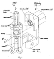
- the principle of the illustrated embodiment is to accurately measure levels of determinand in a water sample which will often contain solid contaminants. This is done by drawing a sample into a cell 10, accurately adding to that sample for example three reagents which will create colour development if the determinand is present. The level of colour development is then measured by passing light of a known band of wavelength through the sample and measuring the light transmission through the sample.
- the head assembly consists of a PTFE piston 12 inside a glass tube, the optical cell 10.
- This piston 12 is drawn up the tube 10 like a syringe by means of lead screw 14, which via two 90 degree bevel gears 16, 18 is driven by a stepper motor 20.
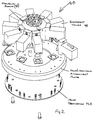
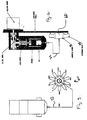
- valve block assembly 40 The sequence in which the solutions are drawn into the cell is determined by the valve block assembly 40.
- This assembly 40 consists of a manifold block 42 and in the example ten diaphragm valves 44 arranged around the manifold 42 in a circular fashion. Eight valves bring in solutions, one valve 44 is for air and the final valve 44 is for waste.
- the head assembly is arranged to draw up the required volume of sample when adopting the method of the present invention, followed by the required volume of the first reagent.
- the light transmission through the sample is taken at this stage so that any background colour can be taken into account.
- the final reagents are drawn into the cell 10.
- the air valve opens and air is drawn into the cell 10 purging the manifold 40 and interconnecting tube 22 of any remaining reagents so that the full volume enters the cell.
- the air is drawn into the cell 10 it rises through the sample and reagent, causing them to be mixed thoroughly and creating a pocket between the solution and the piston 12.
- the waste valve 44 opens and the piston 12 travels down, there is no contact between the piston 12 and solution apart from residue left on the wall of the cell 10. This greatly improves the life of the piston 12 as contact with particles such as sand in the sample now occur rarely.
- the air is last to leave the cell 10 and follows the sample through the interconnecting tube 22 and manifold 40 to waste and purges the system before the next sample is drawn in and hence improves the accuracy of the next measurement.
- the system is particularly designed for sequential measurement.
- the head assembly has been designed so that removal of the head 25 from housing 27 is very easy. Two screws 28 are removed from the head 25 allowing it to slide forward on the supporting arms 22 and to be held in the hand. As the head 25 is removed the drive simply disconnects as the bevel gears 16, 18 separate.
- the LED light source (not shown) and detector (not shown) are housed in the support arms 22 so that they remain in place when the head 25 is removed. This allows for particularly easy maintenance of the unit and this design may be used on any type of optical cell assembly.
- the piston 12 is carried out using a proprietary stepper motor 20, with the associated drive electronics directly controlled by a peripheral micro-controller of a control means (not shown).
- the stepper motor 20 series resistors cause heat which previously was considered a disadvantage to their use as the heat has to be dissipated as waste heat.
- this waste heat is directed into the two aluminium support arms 22 from two 10Watt film resistors (not shown).
- the aluminium support housing 27 acts as a large heat sink to remove heat from inside the enclosure, in turn this causes localised heating of the cell side arms 22 which is selectively conducted into the sample being measured.
- a temperature sensing element (not shown) between the support arms 22, is provided and the signal from the sensing element is fed via suitable electronics into the peripheral micro-controller and control means and thus completes the temperature feedback circuitry to allow selective heating of the optical cell 10.
- the stepper motor 20 may be in three states, running (rotating), stationary (energised), and off (de-energised). During normal operation the stepper motor is predominately not rotating, the control means can utilise the remaining two states to implement on-off temperature control.
- control means permit full 3 term control to be implemented, and therefore temperature of a sample can be altered without requiring an additional heat source or otherwise the overhead of additional heating elements.
- the colourimetric monitor uses the software described in GB application No. 9804616.2 filed on 4th March 1998 with the necessary alteration for colourimetric detection.
- the kernal software may be used.
- the detector apparatus of GB application No. 9804615.4 also filed on 4th March 1998 is also useful in terms of the type of associated hardware and software in the present detector though the present detector is particularly for colourimetric analysis.
- the present invention can be thought of as relating to a colourimetric detector apparatus which is designed to determine liquid samples which habitually contain solid contaminants.
- the invention provides an apparatus and methods where a volume of gas is introduced into the optical cell to promote mixing of the sample and reagents, ensure that full volumes of sample and reagents are supplied to the optical cell and also the gas acts as a buffer between the liquid and the piston to reduce wear on the piston.
Landscapes
- Physics & Mathematics (AREA)
- Health & Medical Sciences (AREA)
- Life Sciences & Earth Sciences (AREA)
- Chemical & Material Sciences (AREA)
- Analytical Chemistry (AREA)
- Biochemistry (AREA)
- General Health & Medical Sciences (AREA)
- General Physics & Mathematics (AREA)
- Immunology (AREA)
- Pathology (AREA)
- Optical Measuring Cells (AREA)
Applications Claiming Priority (2)
| Application Number | Priority Date | Filing Date | Title |
|---|---|---|---|
| GBGB9916807.2A GB9916807D0 (en) | 1999-07-16 | 1999-07-16 | A colourimetric detector |
| GB9916807 | 1999-07-16 |
Publications (2)
| Publication Number | Publication Date |
|---|---|
| EP1069424A2 true EP1069424A2 (de) | 2001-01-17 |
| EP1069424A3 EP1069424A3 (de) | 2002-04-24 |
Family
ID=10857438
Family Applications (1)
| Application Number | Title | Priority Date | Filing Date |
|---|---|---|---|
| EP00305763A Withdrawn EP1069424A3 (de) | 1999-07-16 | 2000-07-07 | Ein kolorimetrischer Detektor |
Country Status (2)
| Country | Link |
|---|---|
| EP (1) | EP1069424A3 (de) |
| GB (1) | GB9916807D0 (de) |
Cited By (1)
| Publication number | Priority date | Publication date | Assignee | Title |
|---|---|---|---|---|
| CN102590094A (zh) * | 2012-02-28 | 2012-07-18 | 何毅 | 一种试剂预封装比色杯 |
Family Cites Families (3)
| Publication number | Priority date | Publication date | Assignee | Title |
|---|---|---|---|---|
| WO1986000703A1 (fr) * | 1984-07-06 | 1986-01-30 | Metrohm Ag | Dispositif et procede pour le dosage quantitatif et/ou qualitatif de liquides |
| US5533978A (en) * | 1994-11-07 | 1996-07-09 | Teirstein; Paul S. | Method and apparatus for uninterrupted delivery of radiographic dye |
| EP0776693A3 (de) * | 1995-11-29 | 1997-08-27 | Lange Gmbh Dr Bruno | Beheizbares Reaktionsgefäss |
-
1999
- 1999-07-16 GB GBGB9916807.2A patent/GB9916807D0/en not_active Ceased
-
2000
- 2000-07-07 EP EP00305763A patent/EP1069424A3/de not_active Withdrawn
Cited By (2)
| Publication number | Priority date | Publication date | Assignee | Title |
|---|---|---|---|---|
| CN102590094A (zh) * | 2012-02-28 | 2012-07-18 | 何毅 | 一种试剂预封装比色杯 |
| CN102590094B (zh) * | 2012-02-28 | 2014-05-28 | 何毅 | 一种试剂预封装比色杯 |
Also Published As
| Publication number | Publication date |
|---|---|
| GB9916807D0 (en) | 1999-09-22 |
| EP1069424A3 (de) | 2002-04-24 |
Similar Documents
| Publication | Publication Date | Title |
|---|---|---|
| EP0636413B1 (de) | Vorrichtung und Verfahren zur Nukleinsäurevervielfältigung | |
| US7948625B2 (en) | Apparatus and methods for analyzing samples | |
| EP2344861B1 (de) | Spektrophotometer mit zwei-proben-modus | |
| US5597733A (en) | Automatic multiple-sample multiple-reagent dispensing method in chemical analyzer | |
| US5475486A (en) | Flow cell system for turbidimeter | |
| WO1997044672B1 (en) | Portable modular blood analyzer with simplified fluid handling sequence | |
| US20060012793A1 (en) | Apparatus and methods for analyzing samples | |
| CN109283138B (zh) | 一种定量进样系统 | |
| JP3525757B2 (ja) | 化学分析装置 | |
| JP3024375B2 (ja) | 自動前処理装置 | |
| WO2008060384A1 (en) | Automatic field portable analyser using discrete sample aliquots | |
| CA2204766A1 (en) | An automated analyzing apparatus for measuring water quality with a cylinder-shaped syringe unit | |
| JPH0526883A (ja) | 自動分析装置 | |
| JPH06194299A (ja) | フローセル装置 | |
| EP1069424A2 (de) | Ein kolorimetrischer Detektor | |
| US5482626A (en) | Analytical liquid test sample filtration apparatus | |
| JP2017134061A (ja) | 計量ポンプの機能性をチェックする方法 | |
| JPH08114601A (ja) | 液体検体の多項目検査分析装置 | |
| CN111337437A (zh) | 液体分析仪 | |
| CN207623217U (zh) | 一种水质自动检测设备 | |
| EP3901610B1 (de) | Testroboter zum messen ungelöster gase in einer flüssigkeit | |
| US4399101A (en) | Stopped-flow apparatus | |
| Daoura et al. | Precise automated control of fluid volumes inside glass capillaries | |
| CN2483709Y (zh) | 微量试样快速定位进样装置 | |
| JPH06213778A (ja) | 自動測光分析器 |
Legal Events
| Date | Code | Title | Description |
|---|---|---|---|
| PUAI | Public reference made under article 153(3) epc to a published international application that has entered the european phase |
Free format text: ORIGINAL CODE: 0009012 |
|
| AK | Designated contracting states |
Kind code of ref document: A2 Designated state(s): AT BE CH CY DE DK ES FI FR GB GR IE IT LI LU MC NL PT SE |
|
| AX | Request for extension of the european patent |
Free format text: AL;LT;LV;MK;RO;SI |
|
| PUAL | Search report despatched |
Free format text: ORIGINAL CODE: 0009013 |
|
| AK | Designated contracting states |
Kind code of ref document: A3 Designated state(s): AT BE CH CY DE DK ES FI FR GB GR IE IT LI LU MC NL PT SE |
|
| AX | Request for extension of the european patent |
Free format text: AL;LT;LV;MK;RO;SI |
|
| 17P | Request for examination filed |
Effective date: 20021023 |
|
| AKX | Designation fees paid |
Free format text: AT BE CH CY DE DK ES FI FR GB GR IE IT LI LU MC NL PT SE |
|
| RAP1 | Party data changed (applicant data changed or rights of an application transferred) |
Owner name: SEVERN TRENT WATER PURIFICATION LIMITED |
|
| 17Q | First examination report despatched |
Effective date: 20031217 |
|
| STAA | Information on the status of an ep patent application or granted ep patent |
Free format text: STATUS: THE APPLICATION IS DEEMED TO BE WITHDRAWN |
|
| 18D | Application deemed to be withdrawn |
Effective date: 20040828 |