The present invention relates to an expansion valve of a refrigerating cycle including a
compressor with variable capacity, according to the preamble part of claim 1 and, further
according to the preamble part of claim 9.
As the compressor in a refrigerating cycle of an air-conditioning system of an automobile
directly is driven by the engine, the speed of compressor cannot be controlled
individually. In order to obtain proper refrigerating ability without limitation by the engine
speed compressors with variable capacity are used, like compressors of the inclined
plate type, the rotary type or the scroll type or the like. The capacity of the compressor is
changed in correspondence to the pressure of the inhaled refrigerant or the inhalation
pressure.
The expansion valve in said refrigerating cycle is controlled corresponding to variation of
the temperature and the pressure of the low-pressure refrigerant supplied from the
evaporator. Since the outlet of the evaporator directly communicates with the inlet of the
compressor, the pressure of the refrigerant exiting the evaporator is equal to the
inhalation pressure of the compressor. Any variations of the pressure at the outlet of the
evaporator directly affect the inhalation pressure of the compressor. If the capacity of
compressor is changed due to a variation of the inhalation pressure and if then the
expansion valve opens and closes suddenly corresponding to the variation of the
capacity of the compressor, even the outlet pressure of the evaporator rapidly and
largely may vary. The degree of the variation of the capacity of the compressor thus is
amplified by variations of the inhalation pressure, since the compressor has to follow the
inhalation pressure variations. Said amplification leads to an undesirable hunting effect
over a certain period of time, e.g. several dozens of seconds up to several minutes in the
flow of the refrigerant.
It is an object of the present invention to provide an expansion valve in a refrigerating
cycle allowing to essentially suppress hunting of the flow of refrigerant as soon as the
expansion valve opens corresponding with a condition according to which the capacity of
the compressor is changed. Suppressing hunting means that the hunting either should
be totally suppressed or at least significantly attenuated.
Said task can be achieved with the features contained in claim 1 and also by the feature
combination of claim 9.
Within the expansion valve the cross-section for the refrigerant passing to the evaporator
is controlled differently within a first stroke section adjacent to the fully closed state
position and within further stroke sections where the valve body already has been lifted
farther from the valve seat bore. In particular, the variation of the cross-section within
the first stroke section is smaller at any stroke increment of the valve body than at stroke
increments of the same magnitude but in the further stroke section. In other words,
during an opening stroke of the expansion valve the gradient of the curve representing
the increase of the cross-section through the valve, i.e. a specific variation per stroke
increment, is flatter within said first stroke section and is steeper within any further stroke
section. The same is true for the movement of the valve body in closing direction. This
operational behaviour of the expansion valve allows to effectively control hunting of the
flow of the refrigerant when the capacity of the compressor is changed. A further,
assisting measure for the effective control of the hunting effect, is to set the value of the
pressure at the outlet of the evaporator for the moment where the expansion valve starts
to open into a certain relation to the maximum inhalation pressure within the range where
the capacity of the compressor is changed, particularly so that the pressure at the outlet
of the evaporator then is equal or lower than said maximum inhalation pressure. This
measure, additionally, allows to effectively suppress the hunting effect and to guarantee
a sufficient cooling effect within the refrigerating cycle.
According to the invention this mainly is the result of the design of the expansion valve
body with a prolongation diving into the valve seat bore within a first opening stroke
section close to the fully closed state position and such that a progressively increasing
variation of the cross-section for the refrigerant only takes place in the second part of the
stroke where the expansion valve opens more progressively. In other words, during the
first opening stroke section the valve body is co-acting with the valve seat bore like a flow
regulator with a controlled throttling effect allowing to control the amount of refrigerant
corresponding to a predetermined ramp function. Said regulating measure is applied
exclusively within the first stroke section and where the influence of the expansion valve
for hunting is the strongest.
Preferred embodiments of the invention are contained in the depending claims.
Embodiments of the invention will be explained with the help of the drawings. In the
drawings is:
- Fig. 1
- a block diagram of a refrigerating cycle,
- Fig. 2
- a schematic cross-section of a compressor and a capacity control
valve defining an actuation pressure shift means in a first
embodiment,
- Fig. 3
- a diagram representing the capacity of the compressor in relation
to inhalation pressure as an illustration of capacity control
characteristics of the compressor in the first embodiment,
- Fig. 4
- a longitudinal sectional view of an expansion valve according to
the first embodiment,
- Fig. 5
- a part of an enlarged longitudinal section of the expansion valve of
Fig. 4,
- Fig. 6
- a diagram of the cross-section of the flow passage in said expansion
valve in relation to the stroke of the valve body in relation to a valve
seat bore,
- Fig. 7
- a part of an enlarged longitudinal section of another embodiment of
the expansion valve,
- Fig. 8
- a diagram of the relation between pressure and temperature
illustrating a saturating curve of the refrigerant and the temperature/
pressure characteristic curve of the refrigerant at the outlet of an
evaporator and when the expansion valve begins to open,
- Fig. 9
- a diagram of the relation between pressure and temperature
illustrating a saturating curve of the refrigerant and another example
of a temperature pressure characteristic curve of the refrigerant at the
outlet of the evaporator and as soon as the expansion valve begins to
open,
- Fig. 10
- a longitudinal section of a capacity control valve of the compressor as
a second embodiment, and
- Fig. 11
- a diagram of the relation between the capacity of the compressor and
the inhalation pressure representing a capacity control characteristic
diagram of the compressor in the second embodiment.
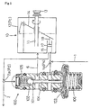
A refrigerating cycle as e.g. used in an air-conditioning system of an automobile has in
Fig. 1 a compressor 10 with variable capacity (amount of discharge). The capacity is
changed corresponding to the inhalation pressure Ps of the refrigerant at an inhalation
duct 1. Inhalation pressure Ps is controlled by a capacity control valve 100. High-pressure
refrigerant having a discharge pressure Pd and as compressed by compressor
10 is supplied in a discharge duct 2 into a condenser 20. Already condensed and
liquified refrigerant temporarily is stored in a receiver 30 with an amount corresponding to
the initial circulation condition. From receiver 30 high-pressure refrigerant in liquid form
is supplied via high- pressure refrigerant ducts 3, 4 to an evaporator 40. Said ducts 3, 4
define a first refrigerant passage in an expansion valve 50 which controls the flow of the
refrigerant. The refrigerant is expanded adiabatically. Low-pressure refrigerant
passing through evaporator 40 is evaporated and returned via a second passage 5 in
said expansion valve 50 to the inhalation duct 1 of compressor 10. The temperature
and the pressure of the refrigerant are sensed at the outlet of the evaporator 40 by a
temperature and pressure sensitive power element 70 of expansion valve 50. Said
power element 70 serves to control said expansion valve opening and closing strokes
depending on variations of the pressure/temperature of the low-pressure refrigerant in
the second passage 5 of expansion valve 50.
In Fig. 2 compressor 10 has a rotatable shaft 11 driven by a belt pulley 13 and disposed
in an airtight crank room 12. Shaft 11 serves to drive a fluctuation board 14 disposed in
crank room 12. Upon rotation of shaft 11 fluctuation board 14 is fulfilling a rocking
motion depending on its inclination in relation to the axis of shaft 11. At least one piston
17 reciprocally is disposed in a cylinder 15 in crank room 12. Piston 17 is connected by
a rod 18 with board 14. When board 14 is rocking piston 17 is reciprocated in cylinder
15. Refrigerant is inhaled from an inhalation room 1a into cylinder 15. Inhalation room
1a communicates with inhalation duct 1. After compression of the refrigerant in cylinder
15 the compressed high pressure refrigerant is discharged into a discharge room 2a
communicating with discharge duct 2.
The inclination angle of the fluctuation board 14 is changed in accordance with a
pressure Pc in crank room 12. The amount of discharged refrigerant, i.e. the capacity of
the compressor 10, is changed according to the inclination angle of the fluctuation board
14. As soon as Pc equals Ps (minimum Pc) compressor 10 is operating with maximum
capacity as shown in solid lines in Fig. 2. If Pc is high compressor 10 is adjusted into the
state of minimum capacity as shown by the dash/dotted position of board 14. Capacity
control valve 100 is situated e.g. in a block in the surrounding of the compressor 10,
particularly in a coaxial multistage bore (not shown). A valve seat 101 is provided in the
middle of a communicating passage between crank room 12 and discharge room 2a
(high-pressure side). A spherical valve body 102 is disposed opposite to valve seat 101
at the side of discharge room 2a. Valve body 102 surveys the communication and is
moveable between open and closed state positions.
A diaphragm 103 separates an inner space of said valve communicating with inhalation
room 1a from an outer space which is sealed airtightly and may contain a reference
pressure. Between a receiving plate which is moveable together with said diaphragm
103 and valve body 102 a central rod 104 interconnects valve body 102 and diaphragm
103 for common movement. Compression coil springs 105 and 106 load diaphragm
103 in opening direction of valve body 102 and in closing direction, respectively. Since
diaphragm 103 is displaced corresponding to variations of inhalation pressure Ps in
relation to the reference pressure loading diaphragm 103, valve body 102 is following
said movements.
As soon as inhalation pressure Ps drops below a fixed pressure value valve body 102 is
separated from valve seat 101. Discharge pressure Pd is brought from discharge room
2a into crank room 12 and control pressure Pc in crank room 12 rises. The capacity of
the compressor 10 is low.
As soon as control pressure Pc in crank room 12 is higher than said fixed pressure
value, valve body 102 is seated on valve seat 101 and the capacity of compressor 10 is
adjusted to maximum capacity, since crank room 12 communicates via a small leak
passage (not shown) with inhalation room 1a. Due to said leak passage control
pressure Pc in crank room 12 drops gradually when valve body 102 is seated such that
after a while valve 102 again will be lifted. As a consequence, control pressure Pc in
crank room 12 continuously is controlled corresponding to the value of the inhalation
pressure Ps and the amount of the capacity of the compressor 10 corresponds to the
value of the inhalation pressure Ps.
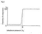
In the diagram of Fig. 3 of the relation between the capacity and the inhalation pressure
Ps value B is the maximum inhalation pressure within the range in which the capacity of
the compressor 10 changes. As soon as inhalation pressure Ps gradually drops below
value B with the compressor 10 running with maximum capacity, the capacity
automatically starts to decrease.
Expansion valve 50 in Fig. 4 has a main body block 51 with second passage (outlet duct
5 of evaporator 40) for the flow of low-temperature and low-pressure refrigerant gas as
supplied from evaporator 40. Main body block 51 in addition has a first passage (duct 3)
into which high-pressure and high-temperature refrigerant fluid is supplied from receiver
30 which fluid is supplied into inlet duct 4 of the evaporator, Said supply of the
refrigerant fluid is carried out adiabatically. Second passage (outlet duct 5) directly
communicates with inhalation duct 1 of compressor 10. The refrigerant pressure in the
outlet duct 5 of the evaporator 40 (outlet pressure of the evaporator 40) is equal to
inhalation pressure Ps of compressor 10.
The first refrigerant passage 3 in main body block 51 has the form of a crank. A
contracted portion of said first passage has a valve seat bore 52. In alignment with
valve seat bore 52 a penetrating bore 58 is formed between said first and second
passages. Said penetrating bore 58 receives a retractable actuation rod 59, one end of
which is connected to a valve body 53 associated to said valve seat bore 52 within said
first passage at the side of high-pressure refrigerant duct 3. Said valve body is loaded
by a compression spring 54 in closing direction. The other end of actuation rod 59 is in
driving connection with a power element 70. Said power element, having a temperature
sensing room, in installed in an opening part of said main body block 51 in alignment with
penetrating bore 58. Power element 70 at least partially is in temperature and pressure
transmitting contact with the refrigerant within said second passage 5 of main block 51.
The section of the first passage extending between valve seat bore 52 and inlet duct 4 to
evaporator 40 serves to adiabatically expand the high-pressure refrigerant.
Compression coil spring 54 is supported by an adjusting nut 56 screwed into a mounting
opening of main body block 51. By adjusting nut 56 the pre-load or energisation force of
compressing coil spring 54 can be adjusted on demand. An O-ring 56 serves to seal
this region.
Actuation rod 59 abuts valve body 53 and passes valve seat bore 52 with radial
clearance such that an annular flow passage is defined between valve seat bore 52 and
said actuation rod 59.
As soon as valve body 53 is separated from valve seat bore 52 by pushing actuation rod
59 via power element 70 counter to the force of compression coil spring 45 the cross-sectional
area for the passing of the high-pressure refrigerant is increasing. The size of
the cross-sectional area depends on the stroke of valve body 53 or the amount of the
stroke of actuation rod 59. Any variation of the cross-sectional area varies the flow or
demand of refrigerant supplied to evaporator 40.
Actuation rod 59 is sealed within penetrating bore 58 by O-.ring 60 so that no refrigerant
is allowed to leak between said first and second passage 50. O-ring is compressed by a
small compression coil spring 61.
A thermal-sensitive room in power element 70 is airtightly closed by a diaphragm 72 fixed
to a housing 71 made from relatively thick metal sheet material. Said diaphragm 72 can
be a thin metallic sheet, e.g. stainless steel sheet metal of a thickness of about 0.1 mm.
At the other side of said thermal-sensitive room of power element 70 a plate 73 is
abutting said diaphragm 72. The other end of actuation rod 59 abuts at the centre of
plate 73. An O-ring 74 seals the mounting opening for power element 70. Said
thermal-sensitive room contains a saturated vapour gas which might be the same as the
refrigerant in the refrigerating cycle or may be similar to it. Between power element 70
and the second passage of main block 51 a bushing 75 is stationarily fixed. Said
bushing 75 is made of a plastic material or the like having low thermal conductivity.
Bushing 75 is penetrated by a ventilation groove 76 in order to establish a
communication between the second passage and the surface of the diaphragm 72
outside said thermal-sensitive room. Low-pressure refrigerant within said second
passage of main block 51 is allowed to pass through ventilation groove 76 towards
diaphragm 72 such that the temperature of the refrigerant within said second passage
(the refrigerant exiting the evaporator 40) slowly is transmitted to the power element 70.
Valve body 53 has a cone-shaped end part with a bore at the top of it into which bore the
lower end of actuation rod 59 engages. A slanted surface of the conical end part of
valve body 53 has a smaller cone angle than the cone angle of the tapered surface
formed at an entrance section of valve seat bore 52.
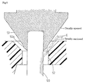
As shown in Fig. 5 at the conical end of valve body 53, which conical end is defining a
conical or convexly rounded seat surface, a bump 53a in the form of a protrusion for
diving into seat valve bore 52 is provided, the outer diameter of which is a little smaller
that the inner diameter of valve seat bore 52 in its cylindrical section continuing the
tapered surface defining the entrance portion of valve seat bore 52. The peripheral and
e.g. cylindrical surface of bump 53a is parallel with the shaft line of actuation rod 59 and
to the inner wall of the cylindrical section of valve seat bore 52. The cone angle of the
slant surface of the protrusion, continuing the peripheral wall of the bump 53a, has a
cone angle which is larger than the cone angle of the seat surface or conical part of
valve body 53. Valve seat bore 52 has a circular closure edge at the transition between
its cylindrical bore action and its tapered entrance section. The conical seat surface of
valve body 53 seats on said closure edge in the fully closed state position. In the fully
closed state position said protrusion or bump 53a is diving into the cylindrical section of
valve seat bore 52.
By the shape of valve body 53 the variation of the cross-section between valve body 53
and valve seat bore 52 is linear within a stroke range between position E where the
bump 53a begins to enter or dive into valve seat bore 52 and the fully opened state
position (maximum opening stroke).
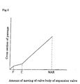
However, as shown in Fig. 6, within a first stroke range E to F (Figs 5 and 6) the
variation of the cross-section of the passage for the refrigerant is much smaller than the
amount of the stroke movement of the valve body 53. Said first stroke range E to F
extends between an opening state position E where the bump 53a begins to dive into the
cylindrical section of valve seat bore 52 and an opening state position F where bump 53a
already has entered the cylindrical bore section of valve seat bore 52 by a considerable
amount and valve body 53 already has closed the valve to some extent. In the
remaining stroke section between opening state position F and the fully closed state
position the relation between the stroke amount of the valve body 53 and the variation of
the cross-section of the passage is similar as outside said first range E to F.
The extent of the valve body moving stroke the stroke section between the fully closed
state position and the opened state position F extends between about 10% to 30% of the
total stroke of valve body 53 into its fully opened state position. The opened state
position E is situated within a range up to less than 50% of the maximum or total stroke
of valve body 53 into its fully opened state position. Within said first stroke section
between positions F and E the variation of the cross-section of the passage for the
refrigerant is smaller in relation to the amount of the moving stroke of the valve body 53
than the variation of the cross-section within the amount of the moving stroke between
the fully closed state position and position F and between position E and the fully opened
state position. In other words, the gradient of the variation of the cross-sectional area in
relation to the stroke movement of valve body 53 is flatter within stroke section F to E
and is steeper in the stroke section between the fully closed state position and position F
as well as between the opened state position E and the fully opened state position
(MAX).
If position F is too close to the fully closed state position or if position E is too close to the
fully opened state position, the moving stroke amount of valve body 53 would be too
large and would cause a problem of endurance. Therefore, it is desirable that positions
E and F are situated within the limits as mentioned above.
A rate of the variation of the cross-section for the moving stroke amount of the valve
body 53 between positions F and E less than one half of the rate of variation of the
cross-section over the other ranges. This is particularly advantageous for controlling
hunting in the flow of the refrigerant. Since it is complicated to achieve a variation of the
cross-section between positions F and E smaller than one fourth than the variation of the
cross-sections in the other stroke sections due to manufacturing limits or the like, a
variation of the cross-section between position F and E amounting between one fourth to
one half of the variation of the cross-section in the other stroke section may be
preferable. Even if the upper limit of the variation of the cross-section between positions
F and E is less than two thirds of the variation of the cross-section in the other stroke
section, this can suffice to get a useful effect when controlling hunting.
In the embodiment shown in Fig. 7 valve body 53 has another design. The transition
between the protrusion or bump 53a and the conical seat surface of valve body 53 is
defined by a constricted part or circumferential groove 53b. This allows to even reduce
the rate of the variation of the cross-section between positions F and E in relation to the
rate of the variation of the cross-section in the other stroke sections.
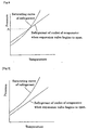
In the temperature/pressure diagram of Fig. 8 a saturating curve of the refrigerant (the
refrigerant circulated through the refrigerating cycle) is shown, as well as a characteristic
curve of the refrigerant in the outlet duct 5 of the evaporator 40 when valve body 53 of
expansion valve 50 starts to open from its fully closed state position. Both curves
intersect each other at a point A, representing a value of the pressure of the refrigerant in
outlet duct 5 of the evaporator being essentially equal to the initial inhalation pressure Ps
of compressor 10.
Provided that the value B in the diagram of Fig. 3 of inhalation pressure Ps is the value at
which the capacity of the compressor 10 will decrease from maximum capacity, the
capacity will not decrease when valve body 53 of expansion valve 50 starts to open, if
value A in the diagram of Fig. 8 was higher than value B of the maximum inhalation
pressure B in the diagram of Fig. 3 in a range where the capacity of compressor 10
should change. Then hunting of the flow of the refrigerant will not occur. However, in
case of high load on the refrigerating cycle, the achievable effect of air-conditioning will
not satisfy and it will be hard to cool sufficiently. Even a liquid phase of the refrigerant
fluid will be forced to return to the compressor 10. Therefore, in order to achieve a
sufficient air-conditioning effect the prerequisite of value A equal to smaller than B should
be satisfied.
If in a conventional refrigerating cycle a setting is made to have value A equal to or
smaller than value B, hunting of the flow of the refrigerant may occur, because the
capacity of the compressor 10 will change immediately when valve body 53 of the
expansion valve 50 begins to open.
However, as according to the invention and in the refrigerating cycle of the embodiment
as described sharp variations of the flow of the refrigerant are suppressed, the flow of the
refrigerant is continuously controlled, and hunting does not occur, since the variation of
the cross-section of the passage for the refrigerant in relation to the lift stroke amount of
valve body 53 is small within the first stroke range between positions F and E when the
expansion valve opens as mentioned above. Said positive control or suppression of
sharp flow variations through the expansion valve 50 even can be achieved when the
characteristic curve of the refrigerant exiting evaporator 40 as soon as expansion valve
50 begins to open does not cross the saturating curve of the refrigerant as shown in Fig.
9. Even then hunting will controlled or suppressed.
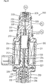
Fig. 10 depicts another embodiment of a capacity control valve 200 used in a
refrigerating cycle of a second embodiment of the invention. Said capacity control valve
200 controls the capacity of compressor 10 in correspondence to inhalation pressure Ps.
The point where the capacity of the compressor starts to change is just the same as
described for the first embodiment. However, with capacity control valve 200 of Fig. 10 it
is possible to arbitrarily shift by a solenoid 210 the range of the inhalation pressure Ps
where the capacity of the compressor starts to change. The further configuration of the
refrigerating cycle is the same as in the first embodiment.
In Fig.. 10 in a middle region of a cylinder 201 of a main body a crank room
communicating part 202 is formed communicating via a side bore with crank room 12.
An end part of said cylinder 201 defines a discharge room communicating part 203
communicating with discharge room 2a via an axial opening. Between parts 202 and
203 a central axial valve bore 204 is provided co-acting with a spherical valve part 205
located in part 203. Part 203 receives a weak compression coil spring 206 loading valve
ball 205 to keep it at the opening of valve ball 204 as long as valve ball 205 is not
pushed upwardly into part 203 against the force of spring 206 by a valve driving rod 207
penetrating valve bore 204 with radial clearance through.
Main body 201 further contains an inhalation room communicating part 208
communicating through a side bore with inhalation room 1a. Valve driving rod 207
extends to the centre of a diaphragm 226. A solenoid 210, consisting of a stationary
electromagnetic coil 211, a stationary fixed iron core 212 at the side of diaphragm 226
and a moveable iron core 214 loosely engaging in one end of inhalation chamber
communicating part 208 is provided. Moveable iron core 214 is loosely inserted in a
sleeve 213 extending inside solenoid 210. An end surface of valve driving rod 207
abuts an end surface of moveable iron core 214. Rod 207 is continued by coaxial rod
221 extending between the other end surface of moveable iron core 214 and the centre
of a plate 225 abutting diaphragm 226. A compression cod spring 221 is disposed
between moveable iron core 214 and fixed iron core 212. Spring 221 has a stronger
spring force than compression coil spring 206 in part 203.
If there is no other force than the force of compression coil spring 221 acting on the
moveable iron core 214 and rod 207, valve ball 205 is lifted from valve bore 204 and is
brought into its fully opened state position. A stopper 222 serves to limit the maximum
opening stroke of valve ball 205.
As soon as electric current is supplied to electromagnetic coil 211 moveable iron coil 214
is attracted by fixed iron core 212 counter to the force of spring 221 causing valve ball
205 to seat on valve bore 204.
Diaphragm 226 is installed close the lower end affixed iron core 212 facing plate 225.
The outer surface of diaphragm 226 is free to ambient air pressure. A space 227 inside
diaphragm 226 (between diaphragm 226 and the lower end of fixed iron core 212)
communicates through a penetrating bore 223 with inhalation room communication part
208. Space 227 can be considered as a part of the inhalation room communicating part
208.
A pressurising mechanism 230 is provided serving to load diaphragm 226 with a
reference pressure in moving direction towards fixed iron core 212. A moveable piston
231 abuts the outer surface of diaphragm 226. Compression coil springs 223 and 234
are provided between moveable piston 231 and a spring counterfort 232 which can be
adjusted to finely adjust the acting forces of compression coil springs 234.
Inhalation pressure Ps is applied on the inner surface of diaphragm 226. The ambient
air pressure and the force of compression coil springs 233 and 234 is applied as said
reference pressure. The resulting difference pressure is applied by diaphragm 226 to
plate 225 and rod 224.
If electric current is supplied to electromagnetic coil 221 of solenoid 210 the pressure
acting on plate 225 acts via rod 224 and moveable iron core 214 at valve driving rod
207. Valve ball 205 is controlled to open and close corresponding to variations of
inhalation pressure Ps. As a consequence the capacity of compressor 10 is controlled.
The value of the inhalation pressure Ps for a change between the open and close
condition of valve ball 205 can be varied or shifted by varying the value of electric
currents for electromagnetic coil 211. This allows to arbitrarily shift the response point
for the initiated capacity change.
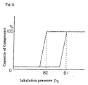
In the diagram of Fig. 11 (relation between capacity and inhalation pressure Ps of the
compressor 10, the capacity of which is controlled by capacity control valve 200)
pressure value B1 is maximum inhalation pressure in the range where the capacity is
changed under the condition that the range of the inhalation pressure Ps by which the
capacity is changed is shifted to the side of the maximum by capacity control valve 200.
Pressure value B2 is the maximum inhalation pressure in the range where the capacity is
changed under the condition that the range of the inhalation pressure Ps by which the
capacity of the compressor is changed is shifted to the side of the minimum by capacity
control valve 200.
If for this embodiment pressure values A and B1 are predetermined such that pressure
value A equals or is smaller than pressure value of B1 as shown in Fig. 8 hunting can be
effectively controlled, If further pressure value A is equal or smaller than pressure value
B2 it is possible to control hunting of the flow of refrigerant and to simultaneously achieve
an excellent cooling ability even conditions where the range of the inhalation pressure Ps
where the capacity is changed, is shifted.
It furthermore is possible to achieve a balance between a satisfying cooling effect and
the hunting control of the flow of the refrigerant by selecting the pressure value A to a
proper pressure value between pressure value B1 and pressure value B2 (pressure B2
equal or smaller than pressure value A equal or smaller than pressure value B1).
The compressor 10 with variable capacity needs not to be an inclined board type, but
may instead be a rotary type, a scroll type or the like.