EP1069383A2 - Hot water accumulator - Google Patents
Hot water accumulator Download PDFInfo
- Publication number
- EP1069383A2 EP1069383A2 EP00114365A EP00114365A EP1069383A2 EP 1069383 A2 EP1069383 A2 EP 1069383A2 EP 00114365 A EP00114365 A EP 00114365A EP 00114365 A EP00114365 A EP 00114365A EP 1069383 A2 EP1069383 A2 EP 1069383A2
- Authority
- EP
- European Patent Office
- Prior art keywords
- water tank
- hot water
- converter
- energy
- process water
- Prior art date
- Legal status (The legal status is an assumption and is not a legal conclusion. Google has not performed a legal analysis and makes no representation as to the accuracy of the status listed.)
- Withdrawn
Links
- XLYOFNOQVPJJNP-UHFFFAOYSA-N water Substances O XLYOFNOQVPJJNP-UHFFFAOYSA-N 0.000 title claims abstract description 57
- 239000000446 fuel Substances 0.000 claims abstract description 16
- 239000000203 mixture Substances 0.000 claims abstract description 7
- 238000000034 method Methods 0.000 claims description 17
- 238000006243 chemical reaction Methods 0.000 claims description 2
- 238000002485 combustion reaction Methods 0.000 abstract description 5
- 238000010438 heat treatment Methods 0.000 abstract 2
- 238000010276 construction Methods 0.000 description 3
- 230000005611 electricity Effects 0.000 description 1
Images
Classifications
-
- F—MECHANICAL ENGINEERING; LIGHTING; HEATING; WEAPONS; BLASTING
- F24—HEATING; RANGES; VENTILATING
- F24H—FLUID HEATERS, e.g. WATER OR AIR HEATERS, HAVING HEAT-GENERATING MEANS, e.g. HEAT PUMPS, IN GENERAL
- F24H1/00—Water heaters, e.g. boilers, continuous-flow heaters or water-storage heaters
-
- F—MECHANICAL ENGINEERING; LIGHTING; HEATING; WEAPONS; BLASTING
- F24—HEATING; RANGES; VENTILATING
- F24H—FLUID HEATERS, e.g. WATER OR AIR HEATERS, HAVING HEAT-GENERATING MEANS, e.g. HEAT PUMPS, IN GENERAL
- F24H1/00—Water heaters, e.g. boilers, continuous-flow heaters or water-storage heaters
- F24H1/18—Water-storage heaters
- F24H1/20—Water-storage heaters with immersed heating elements, e.g. electric elements or furnace tubes
- F24H1/205—Water-storage heaters with immersed heating elements, e.g. electric elements or furnace tubes with furnace tubes
-
- F—MECHANICAL ENGINEERING; LIGHTING; HEATING; WEAPONS; BLASTING
- F24—HEATING; RANGES; VENTILATING
- F24D—DOMESTIC- OR SPACE-HEATING SYSTEMS, e.g. CENTRAL HEATING SYSTEMS; DOMESTIC HOT-WATER SUPPLY SYSTEMS; ELEMENTS OR COMPONENTS THEREFOR
- F24D18/00—Small-scale combined heat and power [CHP] generation systems specially adapted for domestic heating, space heating or domestic hot-water supply
Definitions
- the invention relates to a hot water tank with a storage housing and a hot water tank, in which the hot water in the hot water tank of the heat generated when a fuel mixture is burned is heated and a thermoelectric converter for generating electrical Has energy in the storage housing.
- thermoelectric ones which are also housed in the process water tank or Seebeck facilities.
- the generated electrical Energy is used to electrically supply a pump in the circuit of the Domestic water used.
- the construction of the hot water tank be made so that the energy converter into a chamber in the floor area of the domestic water tank protrudes and that the chamber with a through the hot water tank vertically performed heat exchanger in Connection is made outside the ceiling area of the domestic water tank opens into an exhaust outlet.
- the heat transfer from the heat exchanger to the process water can in the domestic water tank can be improved in that the heat exchanger is designed as a tube provided with outer fins.
- An advantageous construction for the energy converter results from the fact that in the case of a thermal-electrical energy converter, a burner for combustion a fuel mixture is integrated.
- the invention is based on an embodiment shown in the drawing of a thermal-electrical converter explained in more detail.
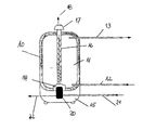
- a domestic water tank 10 divides one within a storage housing 15 Recording room 11 for domestic water.
- the process water is fed through an inlet 12 fed to the domestic water tank 10 and removed via an outlet 13.
- a chamber 14 protrudes, which is part of the Energy converter, especially the part that preferably gives off heat.
- the energy converter 20 integrates in the case of a thermal-electrical Energy converter all parts for mixing and burning the fuel, in particular also the burner, in a unit that is in the storage housing 15 is installed below the hot water tank 10.
- a tubular heat exchanger 16 which acts as a tube, extends from the chamber 14 formed with outer ribs and vertically through the hot water tank 10 is led. Above the ceiling area of the hot water tank 10, the Heat exchanger 16 in an exhaust outlet 17 for the exhaust gas 18.
- the structural unit of the energy converter 20, the fuel 21 to be converted is fed and the generated electrical energy 22 is not only used to supply its own electrical equipment of the hot water tank, but also external Consumers and / or supplied to the public grid.
- the structure of the hot water tank is very simple and it will be a good efficiency in using the energy of the supplied fuel mixture reached.
- the basic structure of the unit does not change when one is on another principle of working energy converter is used.
Landscapes
- Engineering & Computer Science (AREA)
- Physics & Mathematics (AREA)
- Thermal Sciences (AREA)
- Chemical & Material Sciences (AREA)
- Combustion & Propulsion (AREA)
- Mechanical Engineering (AREA)
- General Engineering & Computer Science (AREA)
- Heat-Pump Type And Storage Water Heaters (AREA)
Abstract
Description
Die Erfindung betrifft einen Warmwasserspeicher mit einem Speichergehäuse und einem Brauchwasserbehälter, bei dem das Brauchwasser im Brauchwasserbehälter von der beim Verbrennen eines Brennstoffgemisches erzeugten Wärme aufgeheizt wird und der einen thermoelektrischen Wandler zur Erzeugung elektrischer Energie im Speichergehäuse aufweist.The invention relates to a hot water tank with a storage housing and a hot water tank, in which the hot water in the hot water tank of the heat generated when a fuel mixture is burned is heated and a thermoelectric converter for generating electrical Has energy in the storage housing.
Ein derartiger Warmwasserspeicher ist aus der US 5,495,829 bekannt. Dabei wird das Brennstoffgemisch einem Brenner in einer Brennkammer zugeführt, die über eine Abgasleitung als Wärmetauscher durch den Brauchwasserbehälter geführt ist. Außerdem wird als thermoelektrischer Wandler ein thermoelektrischer Generator nach dem Seebeck-Prinzip verwendet, der die Temperaturdifferenz zwischen der Brennkammer und dem Brauchwasser zur Erzeugung elektrischer Energie ausnützt. Diese elektrische Energie wird vor allen Dingen zur Speisung der elektrischen Einrichtungen des Warmwasserspeichers verwendet. Such a hot water tank is known from US 5,495,829. there the fuel mixture is fed to a burner in a combustion chamber passed through an exhaust pipe as a heat exchanger through the domestic water tank is. In addition, a thermoelectric converter is used as a thermoelectric converter Generator based on the Seebeck principle, which uses the temperature difference between the combustion chamber and the process water for generating electrical Utilizes energy. This electrical energy is primarily used for feeding the electrical equipment of the hot water tank used.
Ein auf ähnlichem Prinzip arbeitender Warmwasserspeicher ist in der WO 97/ 35153 beschrieben. Dabei ist die Wärmequelle im Brauchwasserbehälter untergebracht und von den ebenfalls im Brauchwasserbehälter untergebrachten thermoelektrischen oder Seebeck-Einrichtungen umschlossen. Die erzeugte elektrische Energie wird zur elektrischen Speisung einer Pumpe im Kreislauf des Brauchwassers verwendet.A hot water storage tank operating on a similar principle is described in WO 97 / 35153. The heat source is housed in the domestic water tank and the thermoelectric ones, which are also housed in the process water tank or Seebeck facilities. The generated electrical Energy is used to electrically supply a pump in the circuit of the Domestic water used.
Diese bekannten Warmwasserspeicher haben nicht nur einen kleinen Wirkungsgrad, sie sind im Aufbau auch kompliziert und teuer.These well-known hot water tanks not only have a low efficiency, they are also complicated and expensive to build.
Es ist Aufgabe der Erfindung, einen Warmwasserspeicher der eingangs erwähnten Art nicht nur im Aufbau zu vereinfachen, sondern auch unter optimaler Ausnützung der durch den Brennstoff zugeführten Energie im Wirkungsgrad zu verbessern.It is an object of the invention to provide a hot water tank as mentioned in the introduction Art not only to simplify in construction, but also under optimal Efficiency of the energy supplied by the fuel improve.
Diese Aufgabe wird nach der Erfindung dadurch gelöst, dass der Brennstoff einem Energie-Wandler zugeführt und in diesem umgesetzt wird, dass die bei der Energieumwandlung im Energie-Wandler frei werdende Wärme direkt dem Brauchwasser im Brauchwasserbehälter zugeführt wird und dass die erzeugte elektrische Energie zum Eigenverbrauch verwendet und/oder externen, elektrischen Verbrauchern und/oder dem öffentlichen Stromnetz zugeführt wird.This object is achieved according to the invention in that the fuel an energy converter is supplied and implemented in this that the at Energy conversion in the energy converter releases heat directly to the Process water is supplied in the process water tank and that the generated electrical energy used for own consumption and / or external, electrical Consumers and / or the public power grid is supplied.
Bei dieser Ausgestaltung ist die Wärme- und Stromerzeugung in den Warmwasserspeicher optimal integriert, der damit eine einfache selbständige Einheit bildet. Mit der Betriebszeit des Energie-Wandlers kann auch die erzeugte, elektrische Energie erhöht werden, wobei die anfallende Wärme stets direkt dem zu erwärmenden Brauchwasser im Brauchwasserbehälter zugeführt wird. Die erzeugte elektrische Energie kann nicht nur zur Versorgung der elektrischen Einrichtungen des Warmwasserspeichers, sondern auch zur Deckung einer elektrischen Grundlast oder dgl. in einem Haushalt dienen.In this embodiment, the heat and electricity is generated in the hot water tank optimally integrated, which thus forms a simple, independent unit. With the operating time of the energy converter, the generated electrical can Energy can be increased, the heat generated always directly to be heated Process water is supplied in the process water tank. The generated Electrical energy can not only be used to supply electrical equipment of the hot water tank, but also to cover an electrical base load or the like. Serve in a household.
Nach einer bevorzugten Ausgestaltung kann der Aufbau des Warmwasserspeichers so vorgenommen sein, dass der Energie-Wandler in eine Kammer im Bodenbereich des Brauchwasserbehälters ragt und dass die Kammer mit einem durch den Brauchwasserbehälter vertikal durchgeführten Wärmeübertrager in Verbindung steht, der außerhalb des Deckenbereiches des Brauchwasserbehälters in einen Abgasauslass mündet.According to a preferred embodiment, the construction of the hot water tank be made so that the energy converter into a chamber in the floor area of the domestic water tank protrudes and that the chamber with a through the hot water tank vertically performed heat exchanger in Connection is made outside the ceiling area of the domestic water tank opens into an exhaust outlet.
Dabei kann der Wärmeübergang von dem Wärmeübertrager zum Brauchwasser im Brauchwasserbehälter dadurch verbessert werden, dass der Wärmeübertrager als mit Außenrippen versehenes Rohr ausgebildet ist.The heat transfer from the heat exchanger to the process water can in the domestic water tank can be improved in that the heat exchanger is designed as a tube provided with outer fins.
Eine vorteilhafte Konstruktion für den Energie-Wandler ergibt sich dadurch, dass im Falle eines thermisch-elektrischen Energie-Wandlers ein Brenner zur Verbrennung eines Brennstoffgemisches integriert ist.An advantageous construction for the energy converter results from the fact that in the case of a thermal-electrical energy converter, a burner for combustion a fuel mixture is integrated.
Als Energie-Wandler für derartig aufgebaute Warmwasserspeicher haben sich Stirlingmotoren mit Generator, Brennstoffzellen, Thermophotovoltaik-Wandler und thermoakustische Energie-Wandler mit gutem Wirkungsgrad bewährt. Have proven themselves as energy converters for hot water storage tanks constructed in this way Stirling engines with generator, fuel cells, thermophotovoltaic converter and thermoacoustic energy converters with good efficiency.
Die Erfindung wird anhand eines in der Zeichnung dargestellten Ausführungsbeispiels eines thermisch-elektrischen Wandlers näher erläutert.The invention is based on an embodiment shown in the drawing of a thermal-electrical converter explained in more detail.
Innerhalb eines Speichergehäuses 15 teilt ein Brauchwasserbehälter 10 einen
Aufnahmeraum 11 für Brauchwasser ab. Das Brauchwasser wird über einen Zulauf
12 dem Brauchwasserbehälter 10 zugeführt und über einen Ablauf 13 entnommen.
In den Bodenbereich des Brauchwasserbehälters 10, jedoch noch innerhalb
des Speicherbehälters 15, ragt eine Kammer 14, die einen Teil des
Energie-Wandlers, insbesondere den bevorzugt Wärme abgebenden Teil, aufnimmt.
Der Energie-Wandler 20 integriert im Falle eines thermisch-elektrischen
Energie-Wandlers alle Teile zum Vermischen und Verbrennen des Brennstoffes,
insbesondere also auch den Brenner, in einer Baueinheit, die in dem Speichergehäuse
15 unterhalb des Brauchwasserbehälters 10 eingebaut ist.A
Von der Kammer 14 geht ein rohrförmiger Wärmeübertrager 16 aus, der als Rohr
mit Außenrippen ausgebildet und vertikal durch den Brauchwasserbehälter 10
geführt ist. Über dem Deckenbereich des Brauchwasserbehälters 10 mündet der
Wärmeübertrager 16 in einem Abgasauslass 17 für das Abgas 18. Der Baueinheit
des Energie-Wandlers 20 wird der umzusetzende Brennstoff 21 zugeführt
und die erzeugte elektrische Energie 22 wird nicht nur zur Versorgung eigener
elektrischer Einrichtungen des Warmwasserspeichers, sondern auch externen
Verbrauchern und/oder dem öffentlichen Stromnetz zugeführt.A tubular heat exchanger 16, which acts as a tube, extends from the chamber 14
formed with outer ribs and vertically through the
Die freiwerdende Wärme im Falle eines thermisch-elektrischen Energie-Wandlers
20, in dem ja die Verbrennung des Brennstoffgemisches mittels des integrierten
Brenners erfolgt, gelangt über den Wärmeübertrager 16 direkt an das Brauchwasser
im Brauchwasserbehälter 10.The heat released in the case of a thermal-
Wie die Zeichnung erkennen läßt, ist der Aufbau des Warmwasserspeichers sehr einfach und es wird ein guter Wirkungsgrad bei der Ausnutzung der Energie des zugeführten Brennstoffgemisches erreicht.As the drawing shows, the structure of the hot water tank is very simple and it will be a good efficiency in using the energy of the supplied fuel mixture reached.
Der grundsätzliche Aufbau der Baueinheit ändert sich auch nicht, wenn ein auf anderem Prinzip arbeitender Energie-Wandler engesetzt wird.The basic structure of the unit does not change when one is on another principle of working energy converter is used.
Claims (5)
dadurch gekennzeichnet,
characterized,
dadurch gekennzeichnet,
characterized,
dadurch gekennzeichnet,
characterized,
dadurch gekennzeichnet,
characterized,
dadurch gekennzeichnet,
characterized,
Applications Claiming Priority (2)
| Application Number | Priority Date | Filing Date | Title |
|---|---|---|---|
| DE19932748 | 1999-07-14 | ||
| DE19932748A DE19932748A1 (en) | 1999-07-14 | 1999-07-14 | Hot water tank |
Publications (2)
| Publication Number | Publication Date |
|---|---|
| EP1069383A2 true EP1069383A2 (en) | 2001-01-17 |
| EP1069383A3 EP1069383A3 (en) | 2002-11-13 |
Family
ID=7914640
Family Applications (1)
| Application Number | Title | Priority Date | Filing Date |
|---|---|---|---|
| EP00114365A Withdrawn EP1069383A3 (en) | 1999-07-14 | 2000-07-05 | Hot water accumulator |
Country Status (2)
| Country | Link |
|---|---|
| EP (1) | EP1069383A3 (en) |
| DE (1) | DE19932748A1 (en) |
Cited By (3)
| Publication number | Priority date | Publication date | Assignee | Title |
|---|---|---|---|---|
| EP2894322A1 (en) * | 2014-01-10 | 2015-07-15 | Vaillant GmbH | Cogeneration system |
| ES2546227A1 (en) * | 2014-03-18 | 2015-09-21 | Manuel FRANCISCO LÓPEZ | Water heater device (Machine-translation by Google Translate, not legally binding) |
| EP4100630A4 (en) * | 2020-02-07 | 2024-03-13 | Spark Thermionics, Inc. | SYSTEM AND METHOD FOR COMBINED PRODUCTION OF HEAT AND ELECTRIC ENERGY |
Families Citing this family (1)
| Publication number | Priority date | Publication date | Assignee | Title |
|---|---|---|---|---|
| DE10112671C5 (en) * | 2001-03-16 | 2014-10-09 | Robert Bosch Gmbh | Apparatus for heating service water and for generating electrical energy |
Citations (2)
| Publication number | Priority date | Publication date | Assignee | Title |
|---|---|---|---|---|
| US5495829A (en) | 1994-09-14 | 1996-03-05 | Consolidated Natural Gas Service Company, Inc. | Water heater with thermoelectric module and through-chamber heat sink |
| WO1997035153A1 (en) | 1996-03-16 | 1997-09-25 | University College Cardiff Consultants Limited | Thermo-electric boiler arrangement |
Family Cites Families (5)
| Publication number | Priority date | Publication date | Assignee | Title |
|---|---|---|---|---|
| DE511834C (en) * | 1928-05-27 | 1930-11-01 | Erich Stockmar | Bath stove |
| GB375833A (en) * | 1930-12-31 | 1932-06-30 | Bastian Morley Company | Water heater flue and method of forming same |
| GB2194330B (en) * | 1986-06-27 | 1990-04-04 | Carver & Co | Apparatus for heating a liquid |
| DE9007521U1 (en) * | 1990-05-19 | 1992-04-02 | Stirling Motors GmbH, 5840 Schwerte | Device for generating electrical and heating energy |
| AT402848B (en) * | 1993-03-16 | 1997-09-25 | Vaillant Gmbh | Fluid heater |
-
1999
- 1999-07-14 DE DE19932748A patent/DE19932748A1/en not_active Withdrawn
-
2000
- 2000-07-05 EP EP00114365A patent/EP1069383A3/en not_active Withdrawn
Patent Citations (2)
| Publication number | Priority date | Publication date | Assignee | Title |
|---|---|---|---|---|
| US5495829A (en) | 1994-09-14 | 1996-03-05 | Consolidated Natural Gas Service Company, Inc. | Water heater with thermoelectric module and through-chamber heat sink |
| WO1997035153A1 (en) | 1996-03-16 | 1997-09-25 | University College Cardiff Consultants Limited | Thermo-electric boiler arrangement |
Cited By (3)
| Publication number | Priority date | Publication date | Assignee | Title |
|---|---|---|---|---|
| EP2894322A1 (en) * | 2014-01-10 | 2015-07-15 | Vaillant GmbH | Cogeneration system |
| ES2546227A1 (en) * | 2014-03-18 | 2015-09-21 | Manuel FRANCISCO LÓPEZ | Water heater device (Machine-translation by Google Translate, not legally binding) |
| EP4100630A4 (en) * | 2020-02-07 | 2024-03-13 | Spark Thermionics, Inc. | SYSTEM AND METHOD FOR COMBINED PRODUCTION OF HEAT AND ELECTRIC ENERGY |
Also Published As
| Publication number | Publication date |
|---|---|
| EP1069383A3 (en) | 2002-11-13 |
| DE19932748A1 (en) | 2001-01-25 |
Similar Documents
| Publication | Publication Date | Title |
|---|---|---|
| US4896507A (en) | Solar power system | |
| EP0636280A1 (en) | METHOD AND DEVICE FOR CONVERTING CHEMICAL ENERGY FROM A FUEL TO THERMAL ENERGY AND SIMULTANEOUSLY DIRECTLY TO ELECTRIC ENERGY. | |
| DE4102636C2 (en) | Power supply system with an internal combustion engine and a generator | |
| EP1069383A2 (en) | Hot water accumulator | |
| DE19936591C1 (en) | Gas-driven heat generator, with two-stage cylinder burner including inner and outer burners in common combustion chamber | |
| DE19943613A1 (en) | Heating system for heat and electricity generation | |
| EP0940637B1 (en) | compact energy installation | |
| DE19829192B4 (en) | Energy compact Anlage | |
| EP1643085A1 (en) | Heating installation comprising a gas turbine arrangement and an electric generator | |
| DE10006006A1 (en) | Force-heat coupling equipment sets burner to super-stoichiometric or sub-stoichiometric air ratio values to predominantly acquire heat or to derive electrical energy from fuel cell respectively | |
| DE2601396A1 (en) | Central heating boiler with diesel engine as energy generator - exhaust heat and radiator cooling medium are utilised to heat outer water tank | |
| FI63291C (en) | CENTRAL VEHICLE ADJUSTMENT MED EN MED VATTEN SOM VAERMEBAERANDE MEDIUM ARBETANDE VAERMEPANNA | |
| EP1342033B1 (en) | Gas cooking appliance for the thermal preparation of products to be cooked | |
| DE19822880A1 (en) | Domestic block heating unit for small locations | |
| DE10244343A1 (en) | System for the generation of heat, hot water and convertible energy has gas/air burner, Stirling engine and coupled linear generator in a thermal generation assembly | |
| CN219473616U (en) | Fuel gas steam boiler | |
| DE202021106671U1 (en) | Pellet stove with generator | |
| DE2927196C2 (en) | ||
| DE69215370T2 (en) | POWER GENERATION SYSTEM | |
| DE202004015362U1 (en) | Heating facility for a consumer in a building has a gas/oil combustion chamber to generate hot gases to feed a turbine system for supplying heating and electric power | |
| DE102005022904A1 (en) | Plant for the production of heat energy for heating and heating of drinking water by electrolysis | |
| CN209801765U (en) | Heat energy supply device | |
| DE102009055684A1 (en) | Interconnected electrical component for e.g. power generation, in building, has sunlight-powered photovoltaic system generating primary energy for operation of photovoltaic system in building | |
| DE2405219A1 (en) | Hydrogen and oxygen fired thermal plant - incorporates a boiler, a turbine and electrolytic water dissociation system | |
| DE202006007359U1 (en) | Heat and power supply system for one-family houses has heat exchanger for exhaust system of engine, which supplies thermal energy to hot water tank |
Legal Events
| Date | Code | Title | Description |
|---|---|---|---|
| PUAI | Public reference made under article 153(3) epc to a published international application that has entered the european phase |
Free format text: ORIGINAL CODE: 0009012 |
|
| AK | Designated contracting states |
Kind code of ref document: A2 Designated state(s): AT BE CH CY DE DK ES FI FR GB GR IE IT LI LU MC NL PT SE |
|
| AX | Request for extension of the european patent |
Free format text: AL;LT;LV;MK;RO;SI |
|
| PUAL | Search report despatched |
Free format text: ORIGINAL CODE: 0009013 |
|
| AK | Designated contracting states |
Kind code of ref document: A3 Designated state(s): AT BE CH CY DE DK ES FI FR GB GR IE IT LI LU MC NL PT SE |
|
| AX | Request for extension of the european patent |
Free format text: AL;LT;LV;MK;RO;SI |
|
| AKX | Designation fees paid | ||
| REG | Reference to a national code |
Ref country code: DE Ref legal event code: 8566 |
|
| STAA | Information on the status of an ep patent application or granted ep patent |
Free format text: STATUS: THE APPLICATION IS DEEMED TO BE WITHDRAWN |
|
| 18D | Application deemed to be withdrawn |
Effective date: 20030514 |