DE19829192B4 - Energy compact Anlage - Google Patents
Energy compact Anlage Download PDFInfo
- Publication number
- DE19829192B4 DE19829192B4 DE19829192A DE19829192A DE19829192B4 DE 19829192 B4 DE19829192 B4 DE 19829192B4 DE 19829192 A DE19829192 A DE 19829192A DE 19829192 A DE19829192 A DE 19829192A DE 19829192 B4 DE19829192 B4 DE 19829192B4
- Authority
- DE
- Germany
- Prior art keywords
- energy
- housing
- heat
- heat exchange
- drive unit
- Prior art date
- Legal status (The legal status is an assumption and is not a legal conclusion. Google has not performed a legal analysis and makes no representation as to the accuracy of the status listed.)
- Expired - Fee Related
Links
Classifications
-
- F—MECHANICAL ENGINEERING; LIGHTING; HEATING; WEAPONS; BLASTING
- F02—COMBUSTION ENGINES; HOT-GAS OR COMBUSTION-PRODUCT ENGINE PLANTS
- F02B—INTERNAL-COMBUSTION PISTON ENGINES; COMBUSTION ENGINES IN GENERAL
- F02B63/00—Adaptations of engines for driving pumps, hand-held tools or electric generators; Portable combinations of engines with engine-driven devices
- F02B63/04—Adaptations of engines for driving pumps, hand-held tools or electric generators; Portable combinations of engines with engine-driven devices for electric generators
-
- F—MECHANICAL ENGINEERING; LIGHTING; HEATING; WEAPONS; BLASTING
- F24—HEATING; RANGES; VENTILATING
- F24D—DOMESTIC- OR SPACE-HEATING SYSTEMS, e.g. CENTRAL HEATING SYSTEMS; DOMESTIC HOT-WATER SUPPLY SYSTEMS; ELEMENTS OR COMPONENTS THEREFOR
- F24D18/00—Small-scale combined heat and power [CHP] generation systems specially adapted for domestic heating, space heating or domestic hot-water supply
-
- F—MECHANICAL ENGINEERING; LIGHTING; HEATING; WEAPONS; BLASTING
- F01—MACHINES OR ENGINES IN GENERAL; ENGINE PLANTS IN GENERAL; STEAM ENGINES
- F01K—STEAM ENGINE PLANTS; STEAM ACCUMULATORS; ENGINE PLANTS NOT OTHERWISE PROVIDED FOR; ENGINES USING SPECIAL WORKING FLUIDS OR CYCLES
- F01K23/00—Plants characterised by more than one engine delivering power external to the plant, the engines being driven by different fluids
- F01K23/02—Plants characterised by more than one engine delivering power external to the plant, the engines being driven by different fluids the engine cycles being thermally coupled
- F01K23/06—Plants characterised by more than one engine delivering power external to the plant, the engines being driven by different fluids the engine cycles being thermally coupled combustion heat from one cycle heating the fluid in another cycle
- F01K23/065—Plants characterised by more than one engine delivering power external to the plant, the engines being driven by different fluids the engine cycles being thermally coupled combustion heat from one cycle heating the fluid in another cycle the combustion taking place in an internal combustion piston engine, e.g. a diesel engine
-
- F—MECHANICAL ENGINEERING; LIGHTING; HEATING; WEAPONS; BLASTING
- F02—COMBUSTION ENGINES; HOT-GAS OR COMBUSTION-PRODUCT ENGINE PLANTS
- F02B—INTERNAL-COMBUSTION PISTON ENGINES; COMBUSTION ENGINES IN GENERAL
- F02B77/00—Component parts, details or accessories, not otherwise provided for
- F02B77/11—Thermal or acoustic insulation
- F02B77/13—Acoustic insulation
-
- F—MECHANICAL ENGINEERING; LIGHTING; HEATING; WEAPONS; BLASTING
- F02—COMBUSTION ENGINES; HOT-GAS OR COMBUSTION-PRODUCT ENGINE PLANTS
- F02G—HOT GAS OR COMBUSTION-PRODUCT POSITIVE-DISPLACEMENT ENGINE PLANTS; USE OF WASTE HEAT OF COMBUSTION ENGINES; NOT OTHERWISE PROVIDED FOR
- F02G5/00—Profiting from waste heat of combustion engines, not otherwise provided for
-
- F—MECHANICAL ENGINEERING; LIGHTING; HEATING; WEAPONS; BLASTING
- F24—HEATING; RANGES; VENTILATING
- F24D—DOMESTIC- OR SPACE-HEATING SYSTEMS, e.g. CENTRAL HEATING SYSTEMS; DOMESTIC HOT-WATER SUPPLY SYSTEMS; ELEMENTS OR COMPONENTS THEREFOR
- F24D11/00—Central heating systems using heat accumulated in storage masses
- F24D11/002—Central heating systems using heat accumulated in storage masses water heating system
-
- F—MECHANICAL ENGINEERING; LIGHTING; HEATING; WEAPONS; BLASTING
- F24—HEATING; RANGES; VENTILATING
- F24D—DOMESTIC- OR SPACE-HEATING SYSTEMS, e.g. CENTRAL HEATING SYSTEMS; DOMESTIC HOT-WATER SUPPLY SYSTEMS; ELEMENTS OR COMPONENTS THEREFOR
- F24D3/00—Hot-water central heating systems
- F24D3/08—Hot-water central heating systems in combination with systems for domestic hot-water supply
-
- F—MECHANICAL ENGINEERING; LIGHTING; HEATING; WEAPONS; BLASTING
- F24—HEATING; RANGES; VENTILATING
- F24D—DOMESTIC- OR SPACE-HEATING SYSTEMS, e.g. CENTRAL HEATING SYSTEMS; DOMESTIC HOT-WATER SUPPLY SYSTEMS; ELEMENTS OR COMPONENTS THEREFOR
- F24D2101/00—Electric generators of small-scale CHP systems
- F24D2101/10—Gas turbines; Steam engines or steam turbines; Water turbines, e.g. located in water pipes
-
- F—MECHANICAL ENGINEERING; LIGHTING; HEATING; WEAPONS; BLASTING
- F24—HEATING; RANGES; VENTILATING
- F24D—DOMESTIC- OR SPACE-HEATING SYSTEMS, e.g. CENTRAL HEATING SYSTEMS; DOMESTIC HOT-WATER SUPPLY SYSTEMS; ELEMENTS OR COMPONENTS THEREFOR
- F24D2103/00—Thermal aspects of small-scale CHP systems
- F24D2103/10—Small-scale CHP systems characterised by their heat recovery units
- F24D2103/13—Small-scale CHP systems characterised by their heat recovery units characterised by their heat exchangers
-
- F—MECHANICAL ENGINEERING; LIGHTING; HEATING; WEAPONS; BLASTING
- F24—HEATING; RANGES; VENTILATING
- F24D—DOMESTIC- OR SPACE-HEATING SYSTEMS, e.g. CENTRAL HEATING SYSTEMS; DOMESTIC HOT-WATER SUPPLY SYSTEMS; ELEMENTS OR COMPONENTS THEREFOR
- F24D2105/00—Constructional aspects of small-scale CHP systems
- F24D2105/10—Sound insulation
-
- F—MECHANICAL ENGINEERING; LIGHTING; HEATING; WEAPONS; BLASTING
- F24—HEATING; RANGES; VENTILATING
- F24D—DOMESTIC- OR SPACE-HEATING SYSTEMS, e.g. CENTRAL HEATING SYSTEMS; DOMESTIC HOT-WATER SUPPLY SYSTEMS; ELEMENTS OR COMPONENTS THEREFOR
- F24D2200/00—Heat sources or energy sources
- F24D2200/16—Waste heat
- F24D2200/26—Internal combustion engine
-
- Y—GENERAL TAGGING OF NEW TECHNOLOGICAL DEVELOPMENTS; GENERAL TAGGING OF CROSS-SECTIONAL TECHNOLOGIES SPANNING OVER SEVERAL SECTIONS OF THE IPC; TECHNICAL SUBJECTS COVERED BY FORMER USPC CROSS-REFERENCE ART COLLECTIONS [XRACs] AND DIGESTS
- Y02—TECHNOLOGIES OR APPLICATIONS FOR MITIGATION OR ADAPTATION AGAINST CLIMATE CHANGE
- Y02E—REDUCTION OF GREENHOUSE GAS [GHG] EMISSIONS, RELATED TO ENERGY GENERATION, TRANSMISSION OR DISTRIBUTION
- Y02E20/00—Combustion technologies with mitigation potential
- Y02E20/14—Combined heat and power generation [CHP]
-
- Y—GENERAL TAGGING OF NEW TECHNOLOGICAL DEVELOPMENTS; GENERAL TAGGING OF CROSS-SECTIONAL TECHNOLOGIES SPANNING OVER SEVERAL SECTIONS OF THE IPC; TECHNICAL SUBJECTS COVERED BY FORMER USPC CROSS-REFERENCE ART COLLECTIONS [XRACs] AND DIGESTS
- Y02—TECHNOLOGIES OR APPLICATIONS FOR MITIGATION OR ADAPTATION AGAINST CLIMATE CHANGE
- Y02T—CLIMATE CHANGE MITIGATION TECHNOLOGIES RELATED TO TRANSPORTATION
- Y02T10/00—Road transport of goods or passengers
- Y02T10/10—Internal combustion engine [ICE] based vehicles
- Y02T10/12—Improving ICE efficiencies
Landscapes
- Engineering & Computer Science (AREA)
- Chemical & Material Sciences (AREA)
- Combustion & Propulsion (AREA)
- Mechanical Engineering (AREA)
- General Engineering & Computer Science (AREA)
- Physics & Mathematics (AREA)
- Thermal Sciences (AREA)
- Acoustics & Sound (AREA)
- Water Supply & Treatment (AREA)
- Heat-Pump Type And Storage Water Heaters (AREA)
Abstract
Energie-Kompakt-Anlage mit zumindest einem Antriebsaggregat (2) dem wenigstens ein Generator (5) zugeordnet ist, wobei das Antriebsaggregat (2) zur Nutzung von Abwärme in einem schall- und/oder wärmeisolierenden Gehäuse (1) angeordnet und welchem ein Einlass (19) als Frischluftzufuhr sowie zumindest eine Wärmetauscheinrichtung (11.1, 11.2) zugeordnet ist, dadurch gekennzeichnet, dass die Wärmetauscheinrichtung (11.1) oberhalb des Antriebsaggregates (2) im Gehäuse (1) angeordnet ist und an wenigstens einen Abnehmer (15.1, 15.2) anschliesst und die Wärmetauschereinrichtung (11.2) mit einem Belüftungssystem (18) in Verbindung steht.Energy compact Anlage with at least one drive unit (2) the at least one generator (5) is assigned, wherein the drive unit (2) for the use of waste heat in a sound and / or heat insulating casing (1) arranged and which an inlet (19) as a fresh air supply and at least one heat exchange device (11.1, 11.2) is assigned, characterized in that the heat exchange device (11.1) above the drive unit (2) in the housing (1) is arranged and connected to at least one consumer (15.1, 15.2) and the heat exchanger device (11.2) with a ventilation system (18).

Description
Die vorliegende Erfindung betrifft eine Energie-Kompakt-Anlage mit zumindest einem Antriebsaggregat dem wenigstens ein Generator zugeordnet ist, wobei das Antriebsaggregat zur Nutzung von Abwärme in einem schall- und/oder wärmeisolierendem Gehäuse angeordnet und welchem ein Einlass als Frischluftzufuhr sowie zumindest eine Wärmetauscheinrichtung zugeordnet ist.The The present invention relates to a compact energy system with at least a drive unit to which at least one generator is assigned, wherein the drive unit for the use of waste heat in a sound and / or thermal insulating casing arranged and which an inlet as a fresh air supply and at least a heat exchange device assigned.
Derartige Antriebsaggregate sind in vielfältigster Form und Ausführung auf dem Markt bekannt und gebräuchlich. Sie dienen in erster Linie zum Erzeugen von Energie, insbesondere Strom. Sie zeichnen sich im wesentlichen dadurch aus, dass sie flexibel und unabhängig einzusetzen sind.such Drive units are in manifold ways Shape and design known and in use on the market. They serve primarily to generate energy, in particular Electricity. They are characterized essentially by the fact that they are flexible and independent are to be used.
Nachteilig an derartigen Geräten ist, dass herkömmliche Antriebsaggregate einen hohen Energieverlust aufweisen, da sie ungenutzte Wärme abgeben. Ferner sind sie nicht geeignet, um einen Haushalt vollständig mit allen erforderlichen Energien in unterschiedlicher Form wie bspw. Strom, Wärme etc. zu versorgen.adversely on such devices is that conventional Drive units have a high energy loss, since they are unused Give off heat. Further, they are not suitable to complete a household all required energies in different forms such as. Electricity, heat etc. to supply.
Das
Deutsche Gebrauchsmuster
Die
Die
Nach
der
Der vorliegenden Erfindung liegt die Aufgabe zugrunde eine Energie-Kompakt-Anlage der o.g. Art zu schaffen, welche eine separate und vollständige Energieversorgung bspw. für ein Haus zulässt, wobei ein derartiger Abnehmer völlig unabhängig von externen Energieversorgern, Wohnhäuser oder Wohnungen mit Energie versorgen kann.Of the present invention, the object is based on a compact energy plant the o.g. Kind of creating a separate and complete energy supply for example for a house allows, with such a customer completely independently from external utilities, homes or apartments with energy can provide.
Ferner sollen dabei Energiekosten reduziert und bedarfsgerecht verwendet werden. Zudem soll eine derartige Energie-Kompakt-Anlage universell einsetzbar und in herkömmliche Wohnhäuser nachrüstbar sein.Further Energy costs should be reduced and used as needed become. In addition, such a compact energy system should be universal can be used and in conventional building site upgradeable be.
Zur Lösung dieser Aufgabe führt, dass die Wärmetauscheinrichtung oberhalb des Antriebsaggregates im Gehäuse angeordnet ist und an wenigstens einen Abnehmer anschliesst und die Wärmetauschereinrichtung mit einem Belüftungssystem in Verbindung steht.to solution performs this task, that the heat exchange device is arranged above the drive unit in the housing and at least connects a customer and the heat exchanger device with a ventilation system communicates.
Die vorliegende Erfindung gestattet, dass die von dem Antriebsaggregat abgegebene Wärme und die vom Antriebsaggregat abgegebenen heissen Abgase in zumindest einem Wärmetauscher ausgewertet werden. In dem Gehäuse können verschiedenste Wärmetauscher vorgesehen sein, um die Abwärme eines derartigen Antriebsaggregates zu nutzen.The present invention allows that of the drive unit released heat and the output from the drive unit hot exhaust gases in at least a heat exchanger be evaluated. In the case can various heat exchangers be provided to the waste heat to use such a drive unit.
Ein Wärmetauscher ist vorzugsweise als luft und gasdurchlässiges Register ausgebildet, welches von heisser Luft bzw. auch von heissen Abgasen des Antriebsaggregates durchströmbar ist. Hierdurch wird bspw. warmes Wasser für einen Heizboiler bzw. Heizkreislauf eines Wohnhauses oder für einen Brauchwasserboiler in einem Wohnhaus aufgewärmt. Zusätzlich kann der durch den Generator erzeugte Strom, gesteuert über eine elektrische Steuerung, eine Wärmepumpe oder eine elektrische Heizung, betreiben. Hierdurch lässt sich die gewünschte Brauchwassertemperatur oder Temperatur des Heizkreislaufes im Abnehmer exakt regeln und steuern.One heat exchangers is preferably designed as an air and gas-permeable register, which of hot air or hot exhaust gases of the drive unit flow through is. As a result, for example, hot water for a boiler or heating circuit a residential building or for warmed up a domestic water boiler in a residential building. In addition, can the current generated by the generator, controlled by a electrical control, a heat pump or an electric heater. This allows the desired Hot water temperature or temperature of the heating circuit in the customer exactly regulate and control.
Eine weitere Besonderheit der vorliegenden Erfindung ist dann gegeben, wenn zusätzlich extern oder intern im Gehäuse Energiespeicher, bspw. in Form von Batterien, vorgesehen sind. Dann kann bei geringeren Lasten auf den Betrieb des Antriebsaggregates verzichtet werden, wobei die Lastabnehmer über die Energiespeicher versorgt werden.Another special feature of the present invention is given if in addition externally or internally in the housing energy storage, eg. In the form of batteries, are provided. Then can at lower Loads are waived on the operation of the drive unit, the load being supplied via the energy storage.
Eine weitere besonders vorteilhafte Ausgestaltung der Erfindung zeigt eine zusätzliche Wärmetauscheinrichtung, welche Warmluft zum Beheizen von Räumen, insbesondere über ein Belüftungssystem, in das Gebäude einbringt. Dieser Wärmetauscheinrichtung wird Luft über einen Einlassstutzen zugeführt und erwärmte Luft über einen Auslassstutzen in ein Belüftungssystem zugeführt. Von dort können eine Mehrzahl von Räume beheizt werden.A further particularly advantageous embodiment of the invention shows an additional Heat exchange device, which warm air for heating rooms, in particular over a Ventilation system, in the building brings. This heat exchange device gets air over fed to an inlet nozzle and heated Air over an outlet in a ventilation system fed. From there you can a plurality of rooms be heated.
Insgesamt ist mit der vorliegendnen Erfindung eine Anlage, insbesondere eine Energie-Kompakt-Anlage geschaffen, welche selbstständig und unabhängig von fremden und externen Energien ein Haus oder ein Wohnraum mit Energie versorgen kann. Sind die Abnehmer wie bspw. Brauchwasser, Boiler oder Heizkreislaufboiler nachts nicht im Betrieb und wird in einem Haushalt nur geringfügig Energie verbraucht, so schaltet sich automatisch das Antriebsaggregat ab. Der übrige Energiebedarf wird über die Energiespeicher insbesondere Batterien abgedeckt.All in all is with the present invention a plant, in particular a Energy compact plant created, which independently and independently from foreign and external energies a house or a living space with Can supply energy. Are the customers such as, for example, service water, Boiler or heating circuit boiler at night not in operation and will in a household only slightly Consumption of energy, the drive unit automatically shuts off from. The rest Energy demand is over the energy storage in particular batteries covered.
Ferner entfallen bei einer derartigen Anlage herkömmliche Schornsteinfegerkosten sowie Anschlussgebühren der Energieversorger pro Einfamilienhaus, die in etwa bei DM 4.000,– bis DM 6.000,– liegen. Es können herkömmliche teure Heizkörper, Heizkessel oder Stromversorgungsanlagen etc. entfallen.Further omitted in such a system conventional chimney sweep costs as well as connection fees the energy provider per family house, which is about DM 4,000 to DM 6,000, - lie. It can conventional expensive radiators, Boilers or power supply systems etc. omitted.
Durch die Verwendung von Wohnraumbe- und entlüftungsanlagen wird zugleich der Wohnung zusätzlich die notwendige Frischluft zugeführt. Ferner können durch die Verwendung von Biotreibstoffen als Energielieferanten für das Antriebsaggregat sehr umweltfreundlich und vollständige Energieversorgungen auf engstem Raum preisgünstig ausgenutzt werden.By the use of home ventilation systems will be at the same time the apartment in addition supplied the necessary fresh air. Furthermore, can through the use of biofuels as energy suppliers for the Drive unit very environmentally friendly and complete power supplies reasonably priced in confined spaces be exploited.
In einem weiteren Ausführungsbeispiel der vorliegenden Erfindung wird über eine Wärmetauscheinrichtung, wie sie oben beschrieben ist, Energie bspw. einem Blockheizkraftwerk entzogen. Die Wärmetauscheinrichtung wird ebenfalls über ein Medium, insbesondere Wasser betrieben und führt Wärme einem Abnehmer, insbesondere Boiler zu. Dieser Boiler oder zumindest ein Teil von ihm kann über vorzugsweise externe Energie, bevorzugt mittels eines Brenners, stark erhitzt werden, so dass im Abnehmer bzw. Boiler eine Dampferzeugung stattfindet. Dieser Überdruck, insbesondere dieser Wasserdampf, wird in einem dem Abnehmer zugeordneten Energiewandler, insbesondere Dampfgenerator zu Strom umgewandelt. Hierdurch kann die Abwärme bspw. eines Blockheizkraftwerkes zur direkten Stromerzeugung genutzt werden, was dessen Wirkungsgrad wesentlich steigert.In a further embodiment The present invention is about a heat exchange device, as described above, energy, for example, a combined heat and power plant withdrawn. The heat exchange device is also over a medium, in particular water-operated and leads heat to a customer, in particular Boiler too. This boiler or at least part of it can be over preferably external energy, preferably by means of a burner, strongly heated be so that in the customer or boiler steam generation takes place. This overprint, in particular, this water vapor is assigned to a customer Energy converter, especially steam generator converted to electricity. As a result, the waste heat For example, a combined heat and power plant used for direct power generation which significantly increases its efficiency.
Die Dampfturbinen, welche zur Stromerzeugung eingesetzt werden, können nur mit geringfügigem, zusätzlichen Energieaufwand betrieben werden. Es ist lediglich die Temperaturdifferenz zwischen der Temperatur der Abwärme und der Temperatur, welche zur Dampferzeugung notwendig ist, erforderlich. Ebenfalls wird das Kondensat, welches an dem Dampfgenerator abfällt und dessen Temperatur in etwa bei 90°C liegt, dem Abnehmer, insbesondere dem Boiler wieder zugeführt.The Steam turbines, which are used to generate electricity, can only with slight, additional Energy expenditure to be operated. It's just the temperature difference between the temperature of the waste heat and the temperature necessary for steam generation is required. Also, the condensate, which falls off the steam generator and its temperature is about 90 ° C is returned to the customer, in particular the boiler again.
Hierdurch wird die Abwärme eines derartigen Blockheizkraftwerkes, welches bspw. nach herkömmlicher Art durch fossile Brennstoffe, wie Gas, Öl, Biobrennstoffe, Holzschnipsel, Altöl oder anderen fossilen Brennstoffen betrieben wird, ausgenutzt.hereby is the waste heat Such a cogeneration plant, which, for example, according to conventional Fossil fuel type, such as gas, oil, biofuels, wood chips, Used oil or other fossil fuels is exploited.
Ferner müssen derartige Blockheizkraftwerke gekühlt werden, wozu frisches Brauchwasser verwendet wird. Dieses wird dem Kreislauf zugeführt. Es erwärmt sich und muss dann über Kühlflächen abgeleitet und luftgekühlt werden. Hierzu können Düsen oder Ventilatoren vorgesehen sein, welche die Umgebungsluft direkt unter der warmwasserführenden Fläche abführt, so dass das Wasser besser gekühlt werden kann. Dieses Wasser kann über Becken, Erdbecken oder Erdauffangbehälter gesammelt werden. Diese sind in gewissen Abständen aneinandergereiht, um die Abkühlung von einem Becken zum nächsten bis zur gewünschten Wassertemperatur zu gewährleisten. Aus dem letzten, jeweils erkaltetem Becken, wird das kalte Wasser zur Kühlung der Heizkraftwerke erneut in dessen Kreislauf gebracht. Zudem kann das vollständige Wasserreservoir bspw. unter der Verwendung von Regenwasser nachgefüllt werden, damit immer genügend frisches Wasser im Umlauf ist. Entsprechende Überläufe regeln das Wasserreservoir.Further have to Such cogeneration plants are cooled, including fresh water is used. This is fed to the circulation. It heats up and then has to be dissipated via cooling surfaces and air-cooled become. You can do this Nozzles or Fans are provided, which directly under the ambient air the warm water leading area dissipates, so that the water is better cooled can be. This water can over Basin, earth basin or earth collector are collected. These are at certain intervals strung together to cool off from one basin to the next to the desired To ensure water temperature. From the last, each cold pool, the cold water for cooling the cogeneration plants again brought into its circulation. In addition, can the whole Water reservoir, for example, be refilled using rainwater, with it always enough fresh water is in circulation. Corresponding overflows regulate the water reservoir.
Weitere Vorteile, Merkmale und Einzelheiten der Erfindung ergeben sich aus der nachfolgenden Beschreibung bevorzugter Ausführungsbeispiele sowie anhand der Zeichnung; diese zeigt inFurther Advantages, features and details of the invention will become apparent the following description of preferred embodiments and by reference the drawing; this shows in
Gemäss
Das
Antriebsaggregat
Die
Anlage R liefert bspw. nachts ohne dass der Generator
Eine
weitere Besonderheit der vorliegenden Erfindung ist, dass die Abwärme des
Antriebsaggregates
Die
Wärmetauscheinrichtung
Die
Wärmetauscheinrichtung
Ein
weiterer Wärmetauscher
Gemäss
Insbesondere
gelangt in diesem Ausführungsbeispiel
durch Abwärme
vorgewärmtes
Wasser in den Abnehmer
Das
durch Abwärme
erwärmte
Wasser im Abnehmer
Die
Temperatur im Abnehmer
Die
Abwärme,
welche bspw. über
Blockheizkraftwerke gewonnen wird, erwärmt das Wasser im Abnehmer
Daher
wird die Temperatur im Abnehmer
In
dem Ausführungsbeispiel
der vorliegenden Erfindung gemäss
Bezugszeichenliste 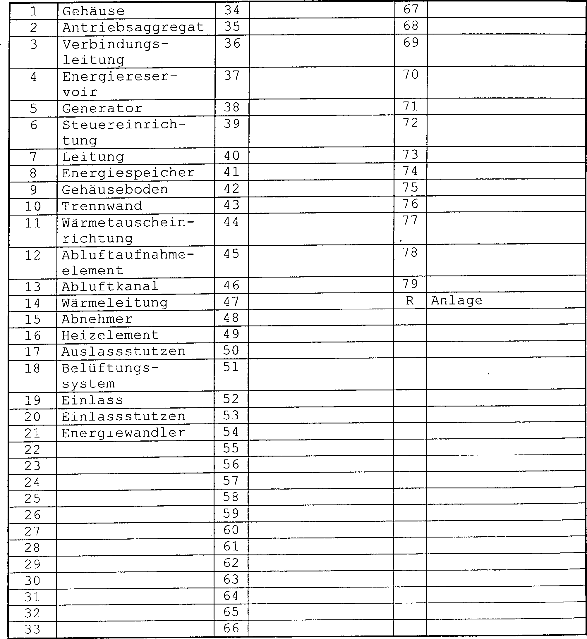
Claims (10)
Priority Applications (5)
| Application Number | Priority Date | Filing Date | Title |
|---|---|---|---|
| DE19829192A DE19829192B4 (en) | 1998-03-06 | 1998-06-30 | Energy compact Anlage |
| DE29812982U DE29812982U1 (en) | 1998-03-06 | 1998-07-21 | Plant for generating energy, in particular compact energy plant |
| EP99103647A EP0940637B1 (en) | 1998-03-06 | 1999-02-25 | compact energy installation |
| ES99103647T ES2247742T3 (en) | 1998-03-06 | 1999-02-25 | COMPACT EQUIPMENT FOR ENERGY PRODUCTION. |
| DE59912691T DE59912691D1 (en) | 1998-03-06 | 1999-02-25 | Energy compact Anlage |
Applications Claiming Priority (3)
| Application Number | Priority Date | Filing Date | Title |
|---|---|---|---|
| DE19809779 | 1998-03-06 | ||
| DE19809779.4 | 1998-03-06 | ||
| DE19829192A DE19829192B4 (en) | 1998-03-06 | 1998-06-30 | Energy compact Anlage |
Publications (2)
| Publication Number | Publication Date |
|---|---|
| DE19829192A1 DE19829192A1 (en) | 1999-09-16 |
| DE19829192B4 true DE19829192B4 (en) | 2005-10-06 |
Family
ID=7860040
Family Applications (1)
| Application Number | Title | Priority Date | Filing Date |
|---|---|---|---|
| DE19829192A Expired - Fee Related DE19829192B4 (en) | 1998-03-06 | 1998-06-30 | Energy compact Anlage |
Country Status (1)
| Country | Link |
|---|---|
| DE (1) | DE19829192B4 (en) |
Cited By (1)
| Publication number | Priority date | Publication date | Assignee | Title |
|---|---|---|---|---|
| DE102009006361A1 (en) | 2009-01-28 | 2010-07-29 | Torsten Enders | Heat and electric current producing method for building, involves arranging and interconnecting lamella heat exchanger, fans, gas heat exchanger, combustion engine and generator, and decoupling air circulation element in closed system |
Families Citing this family (7)
| Publication number | Priority date | Publication date | Assignee | Title |
|---|---|---|---|---|
| DE10010795A1 (en) * | 2000-03-08 | 2001-09-20 | Kamat Pumpen Gmbh & Co Kg | Device to utilise steam for the production of electricity; has steam driven turbine unit connected between steam supply line and low-pressure condenser to drive electricity generator |
| DE10043547A1 (en) * | 2000-09-05 | 2002-03-28 | Schako Metallwarenfabrik | Compact power generator for household applications, has additional heat exchangers for utilizing lost heat to produce steam for driving turbine generator |
| DE102004033360A1 (en) * | 2004-07-05 | 2006-02-09 | Facilitycontrol Ingenieursgesellschaft Mbh | Device for recovering electrical energy using power-heat coupling for driving machines comprises a combustion chamber coupled with a thermal engine which is connected to a generator producing an electrical current |
| ITBO20070055A1 (en) * | 2007-01-29 | 2008-07-30 | Samaya S R L | PLANT FOR THE PRODUCTION OF VEGETABLE OIL ENERGY |
| DE102013015503A1 (en) * | 2013-02-06 | 2014-08-07 | Walter Pragst | Output control assembly for power plants, has electric water heater that is heated at too low heat availability, such that increase in power consumption causes waste heat |
| DE102013114159A1 (en) * | 2013-04-12 | 2014-10-16 | Arvid Rauchschwalbe | Methods and apparatus for using thermal energy and for generating temperature level differences |
| NL2026934B1 (en) * | 2020-11-20 | 2022-07-01 | Helena Sustainable Innovations B V | Building provided with an air or ground source heat pump |
Citations (6)
| Publication number | Priority date | Publication date | Assignee | Title |
|---|---|---|---|---|
| DE8526501U1 (en) * | 1985-09-17 | 1986-02-27 | Hsieh, Sheng-Ming, Kaohsiung | Air conditioner |
| DE4111298A1 (en) * | 1991-04-08 | 1992-10-15 | Gottfried Dipl Ing Roessle | Heat exchanger for small power generating plant - contains exchanger battery as plant cooler, combustion chamber, and waste gas intake chamber |
| DE4237532A1 (en) * | 1992-11-06 | 1993-05-13 | Rudolf Schaper | Heat exchanger for air-cooled block heating plant - effects heat exchange between internal combustion engine and heating system by air exchange |
| DE9405466U1 (en) * | 1994-03-31 | 1994-06-09 | Sächsische Landesgewerbeförderungsgesellschaft mbH, 09131 Chemnitz | CHP plant |
| DE3912256C2 (en) * | 1988-10-04 | 1996-05-09 | Kubota Ltd | Soundproof motor-driven work machine with waste heat recovery device |
| DE19636057C1 (en) * | 1996-09-05 | 1998-03-05 | Lothar Bauer | Plant for the combined generation of mechanical drive energy and steam by means of liquid-cooled internal combustion engines |
-
1998
- 1998-06-30 DE DE19829192A patent/DE19829192B4/en not_active Expired - Fee Related
Patent Citations (6)
| Publication number | Priority date | Publication date | Assignee | Title |
|---|---|---|---|---|
| DE8526501U1 (en) * | 1985-09-17 | 1986-02-27 | Hsieh, Sheng-Ming, Kaohsiung | Air conditioner |
| DE3912256C2 (en) * | 1988-10-04 | 1996-05-09 | Kubota Ltd | Soundproof motor-driven work machine with waste heat recovery device |
| DE4111298A1 (en) * | 1991-04-08 | 1992-10-15 | Gottfried Dipl Ing Roessle | Heat exchanger for small power generating plant - contains exchanger battery as plant cooler, combustion chamber, and waste gas intake chamber |
| DE4237532A1 (en) * | 1992-11-06 | 1993-05-13 | Rudolf Schaper | Heat exchanger for air-cooled block heating plant - effects heat exchange between internal combustion engine and heating system by air exchange |
| DE9405466U1 (en) * | 1994-03-31 | 1994-06-09 | Sächsische Landesgewerbeförderungsgesellschaft mbH, 09131 Chemnitz | CHP plant |
| DE19636057C1 (en) * | 1996-09-05 | 1998-03-05 | Lothar Bauer | Plant for the combined generation of mechanical drive energy and steam by means of liquid-cooled internal combustion engines |
Cited By (1)
| Publication number | Priority date | Publication date | Assignee | Title |
|---|---|---|---|---|
| DE102009006361A1 (en) | 2009-01-28 | 2010-07-29 | Torsten Enders | Heat and electric current producing method for building, involves arranging and interconnecting lamella heat exchanger, fans, gas heat exchanger, combustion engine and generator, and decoupling air circulation element in closed system |
Also Published As
| Publication number | Publication date |
|---|---|
| DE19829192A1 (en) | 1999-09-16 |
Similar Documents
| Publication | Publication Date | Title |
|---|---|---|
| DE4006742C2 (en) | ||
| DE19740398C2 (en) | Combined heat and power facility for energy supply | |
| DE102009011475A1 (en) | Modular combined heat and power plant | |
| DE19829192B4 (en) | Energy compact Anlage | |
| EP0940637B1 (en) | compact energy installation | |
| DE102008016577A1 (en) | Heat pump device for use as heat source to heat e.g. living space, has air/air-compact heat pumps in dimension of electrical storage heater, and housing comprising sound-proof portion, in which compressor is arranged | |
| DE102007063141A1 (en) | Heating device for heating a building by means of a heat pump driven by an internal combustion engine | |
| EP1131583B1 (en) | Device and method for heating and/or ventilating a room | |
| EP1083393B1 (en) | Heating system for producing heat and electricity | |
| EP1400764A1 (en) | Hot-water preparation system | |
| DE10142779A1 (en) | Compact heater, especially for low energy or passive homes, includes three hydraulic circuits connected to heat exchanger elements and water storage tank | |
| DE102004023026A1 (en) | Gas-water heat exchanger for providing hot water in building consists of pipe wound in double spiral coil round flue rising vertically from combustion chamber of fire | |
| DE102016103008B4 (en) | Energy center and operating procedures | |
| EP2444051A1 (en) | Method for economical and ecological operation of a sauna and device for executing the method | |
| DE202009016299U1 (en) | Plant for generating electricity and / or heat | |
| DE10043547A1 (en) | Compact power generator for household applications, has additional heat exchangers for utilizing lost heat to produce steam for driving turbine generator | |
| DE10149339C1 (en) | Heating system for use in house includes room heating and water heating circuits incorporates heat exchanger cooling used air passed to outside and heating fresh air drawn in from outside | |
| DE10313415B4 (en) | System for supplying consumers with hot water | |
| DE202005009663U1 (en) | Combined heat and power generator for generating thermal and electrical energy from fossil fuel energy, has summer mode for heating domestic water using environmental heat | |
| DE102008019614A1 (en) | Electricity generating heater | |
| EP1288581A2 (en) | Compact boiler | |
| AT413424B (en) | ENVIRONMENTALLY FRIENDLY SYSTEM FOR HEATING AND / OR COOLING BUILDINGS | |
| DE102006039341A1 (en) | Power supply system for electricity and power for supply of electrical building network with electrical energy, has compressor, driven by engine by interconnection of switchable clutch, is switched in refrigerant circuit cooling medium | |
| AT255079B (en) | Heating system for an apartment or a residential building with a hot-air bath room (sauna) | |
| DE7715448U1 (en) | Insulating cell for heat pumps, heat accumulators and hot water boilers in central heating systems |
Legal Events
| Date | Code | Title | Description |
|---|---|---|---|
| OP8 | Request for examination as to paragraph 44 patent law | ||
| 8364 | No opposition during term of opposition | ||
| 8339 | Ceased/non-payment of the annual fee |