EP1069360A2 - Support de fixation de cables - Google Patents
Support de fixation de cables Download PDFInfo
- Publication number
- EP1069360A2 EP1069360A2 EP00305522A EP00305522A EP1069360A2 EP 1069360 A2 EP1069360 A2 EP 1069360A2 EP 00305522 A EP00305522 A EP 00305522A EP 00305522 A EP00305522 A EP 00305522A EP 1069360 A2 EP1069360 A2 EP 1069360A2
- Authority
- EP
- European Patent Office
- Prior art keywords
- curvature
- flexible cables
- attachment portion
- strap
- saddle
- Prior art date
- Legal status (The legal status is an assumption and is not a legal conclusion. Google has not performed a legal analysis and makes no representation as to the accuracy of the status listed.)
- Withdrawn
Links
- 230000001154 acute effect Effects 0.000 claims description 10
- 238000005728 strengthening Methods 0.000 claims description 5
- 230000006978 adaptation Effects 0.000 description 2
- 238000012986 modification Methods 0.000 description 2
- 230000004048 modification Effects 0.000 description 2
- 238000007665 sagging Methods 0.000 description 2
- 230000005540 biological transmission Effects 0.000 description 1
- 238000010276 construction Methods 0.000 description 1
- 239000002184 metal Substances 0.000 description 1
- 239000000126 substance Substances 0.000 description 1
Images


Classifications
-
- F—MECHANICAL ENGINEERING; LIGHTING; HEATING; WEAPONS; BLASTING
- F16—ENGINEERING ELEMENTS AND UNITS; GENERAL MEASURES FOR PRODUCING AND MAINTAINING EFFECTIVE FUNCTIONING OF MACHINES OR INSTALLATIONS; THERMAL INSULATION IN GENERAL
- F16L—PIPES; JOINTS OR FITTINGS FOR PIPES; SUPPORTS FOR PIPES, CABLES OR PROTECTIVE TUBING; MEANS FOR THERMAL INSULATION IN GENERAL
- F16L3/00—Supports for pipes, cables or protective tubing, e.g. hangers, holders, clamps, cleats, clips, brackets
- F16L3/02—Supports for pipes, cables or protective tubing, e.g. hangers, holders, clamps, cleats, clips, brackets partly surrounding the pipes, cables or protective tubing
Definitions
- the present invention relates generally to devices for supporting flexible electrical cables.
- One known cable supporting bracket of this general type is disclosed in Perrault U.S. Patent No. 4,039,131.
- This type of bracket has a 'J' configuration and is generally referred to as a 'J-Hook', and it includes a flat cable supporting surface formed with a curvature to contain the supported cable or cables, and a downwardly extending flange is provided at each outer edge of the flat cable supporting surface to strengthen the bracket.
- the corners between the flat supporting surface and the two downwardly extending flanges are rounded, and are intended to avoid exposing the supported cables to a sharp edge which might damage the cables.
- Laughlin U. S. Patent No. 5,740,994 discloses a cable supporting bracket which also includes a flat cable supporting surface being formed with a curvature for containing the cable(s), and a stiffening or strengthening flange formed at each side edge of the flat supporting surface with rounded corners therebetween.
- the stiffening flanges extend downwardly and outwardly from the flat supporting surface at an angle of forty-five degrees, and this angle, combined with the rounded surface, also reduces the sharpness of the sharp corners or edges that might damage the supported cables.
- the present invention provides, in a first aspect, a device for supporting flexible cables, comprising:
- the present invention provides a device for supporting flexible cables, comprising:
- the present invention provides a device for supporting flexible cables, comprising:
- a device for supporting flexible cables which comprises an attachment portion by which the device is attached to a mounting member, such attachment portion having a generally longitudinal extent and openings therein for receiving said mounting members, and a support portion formed integrally with the attachment portion at one of its longitudinal ends and extending therefrom along a centerline having a confining configuration that forms a saddle for containing the flexible cables.
- the support portion has a support surface formed with a rounded configuration that curves away and downwardly from the centerline in both directions with a radius of curvature that provides a contour generally similar to the contour of the flexible cables supported and contained within said saddle.
- the centerline of the support portion has a curved configuration
- the support surface is formed with a rounded configuration that curves away and downwardly from said centerline in both directions with a constant radius of curvature.
- the support surface may be formed with a channel extending along the centerline of the saddle, the channel having a predetermined depth and having a bottom wall formed with a radius of curvature extending from the same center as said radius of curvature of the support surface.
- a strap is disposed within the channel for assisting in maintaining the cables within the saddle, such strap having a thickness corresponding to the depth of the channel whereby the contour of the top surface of the strap forms a curvature corresponding to the curvature of the major portion of the support surface and the top surfaces of the strap and the support surface form a continuous curved surface.
- the configuration of the support portion is generally triangular, and includes a first leg extending downwardly and away from the attachment portion in angular relation thereto, a second leg extending from the first leg at an acute angle and generally perpendicular to the longitudinal extent of the attachment portion, and a third leg extending upwardly from the second leg at an acute angle.
- the second leg of the support portion has a support surface formed with a rounded configuration that curves away and downwardly from the centerline in both directions with a constant radius of curvature that provides a contour generally similar to the contour of the flexible cables supported and contained within the saddle.
- Figs. 1-4 illustrate one embodiment of a device for supporting flexible cables in accordance with the present invention.
- the device is a J-Hook 10 that includes an attachment portion 12 by which the device is attached to a mounting member, and this attachment portion 12 has a generally longitudinal extent and is formed with openings 14 that are designed to receive a variety of conventional mounting members, such as ceiling fasteners, drop wire clips, and vertically depending straps utilizing clips 16, two of which are illustrated in Fig. 2.
- the J-Hook 10 also includes a support portion 18 that is formed integrally with the attachment portion 12 at the lower longitudinal end of the attached portion 12, and the support portion 18 extends therefrom along a centerline having a confining configuration that forms a saddle 20 for containing flexible electrical cables and the like as described above.
- the support portion 18 is formed with a support surface 22 having a rounded configuration that curves away and downwardly from the center line of the support portion 18, in both directions.
- this rounded configuration is formed with a radius of curvature that provides a contour generally similar to the contour of the flexible cables that are to be supported and contained within the saddle 20.
- this radius of curvature is within the range of 50.8cm (two inches) to 101.6cm (four inches).
- the support surface 22 offers a full radius cross-sectional shape that provides cables with a smooth continuous surface on which the cables may lie, as best seen in Fig. 10.
- the J-Hooks 10 when a plurality of the J-Hooks 10 are mounted at spaced locations from one another, as generally suggested by industry standards, one or more electrical cables 24 are supported at the spaced locations by the J-Hooks 10. Because of the inherent weight of the electrical cables 24 and the spacing between the J-Hooks 10, there is some sag of the cables 24 between adjacent J-Hooks 10 as diagrammatically illustrated in Fig. 10, so that the electrical cables 24 assume a generally sinuous shape.
- This shape conforms nicely to the aforesaid curvature of the support surface 22 to provide a full, complete and continuous support for the cables 24 without the cables having to pass over sharp edges or having a curvature that leaves a portion of the electrical cable 24 unsupported.
- FIGs. 5-7 Another embodiment of the present invention is illustrated in Figs. 5-7, which comprises a J-Hook that is identical to the J-Hook 10 described above in connection with Figs. 1-4 except that a strap 26 is attached to the support portion 18 of the J-Hook 10 whereby the cables supported within the saddle 20 can be securely held in place by the strap 26.
- the support portion is formed with a channel 28 that extends along the center line of the support portion 18, and the strap 26 is mounted therein using rivets or any other conventional fastening device (not shown).
- the channel 28 has a bottom wall 30 that is formed with a radius of curvature extending from the same center as the aforesaid radius of curvature of the support surface 22.
- the depth of the channel 28 corresponds to the thickness of the strap 26, and this depth, combined with the radius of curvature of the bottom wall 30, support the strap 26 so that the contour of the top surface of the strap 26 forms a curvature corresponding to the aforesaid curvature of the support surface 22. Accordingly, the upper surface of the strap 26 and the surface of the support portion 18 provide a smooth and continuous curved surface for properly supporting an electrical cable passing thereover.
- the strap 26 is formed at its extending ends with a conventional Velcro® hook-and-loop construction that permits the two end portions to be connected to each other at any desired location to hold electrical cables securely in place within the saddle 20.
- Velcro® spots 32 are mounted in the attachment portion 12 and on the outside surface of the support portion 18 as best illustrated in Fig. 5.
- the extending ends of the strap 26 can be temporarily secured to the two Velcro® spots 32 so that the extending ends of the strap 26 will be maintained at a position that will not interfere with the electrical cables as they are moved into and out of the saddle 20 of the J-Hook 10.
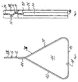
- the cable supporting device also includes an attachment portion 34 by which the device is attached to mounting members as described above, and the attachment portion 34 has a generally longitudinal extent and is formed with openings for receiving mounting members of the aforesaid types.
- the support portion 36 is also formed integrally with the attachment portion 12 and it has a generally triangular configuration which includes a first leg portion 38 that extends downwardly and away from the attachment portion 34 in angular relation thereto, a second leg portion 40 extending from the first leg portion 38 at an acute angle and in a direction generally perpendicular to the longitudinal extent of the attachment portion 34, and a third portion 42 that extends upwardly for the second leg portion 40 at an acute angle.
- the third leg portion 42 is preferably formed at its upper extending end, with a flat flange 44.
- the support portion 36 is preferably formed of a metal that has a desired amount of resiliency so that the third leg portion 42 is normally biased to a position at which the flat flange 44 engages an adjacent surface of the attachment portion 34 to provide a closed saddle 46 to receive and support electrical cables therein.
- the third leg portion 42 can be moved against its bias to separate the flat flange 44 from the attachment portion 44 to provide an opening for loading or unloading cables within the saddle 46.
- the support portion of 36 is formed with a support surface 48 that is identical to the support surface described in connection with the embodiments illustrated in Figs. 1-7, and the support surface 48 may be formed with a smooth continuous surface which does not include any strap, in a manner identical to that described in connection with the embodiment illustrated in Figs. 1-4 or, as illustrated in Figs. 8 and 9, it can be formed with a channel 50 and a strap 52 that are, again, identical to the channel and strap described above in connection with the embodiment of the invention illustrated in Figs. 5-7. In either case, electrical cables within the saddle 46 are supported on a smooth, continuous surface, having a radius of curvature that conforms to the curvature of the cables in the same manner as that described above.
Landscapes
- Engineering & Computer Science (AREA)
- General Engineering & Computer Science (AREA)
- Mechanical Engineering (AREA)
- Installation Of Indoor Wiring (AREA)
- Supports For Pipes And Cables (AREA)
- Laying Of Electric Cables Or Lines Outside (AREA)
Applications Claiming Priority (2)
| Application Number | Priority Date | Filing Date | Title |
|---|---|---|---|
| US35156499A | 1999-07-12 | 1999-07-12 | |
| US351564 | 1999-07-12 |
Publications (2)
| Publication Number | Publication Date |
|---|---|
| EP1069360A2 true EP1069360A2 (fr) | 2001-01-17 |
| EP1069360A3 EP1069360A3 (fr) | 2003-04-23 |
Family
ID=23381420
Family Applications (1)
| Application Number | Title | Priority Date | Filing Date |
|---|---|---|---|
| EP00305522A Withdrawn EP1069360A3 (fr) | 1999-07-12 | 2000-06-30 | Support de fixation de cables |
Country Status (3)
| Country | Link |
|---|---|
| US (1) | US6332594B2 (fr) |
| EP (1) | EP1069360A3 (fr) |
| MX (1) | MXPA00004984A (fr) |
Cited By (3)
| Publication number | Priority date | Publication date | Assignee | Title |
|---|---|---|---|---|
| WO2003058106A1 (fr) * | 2001-12-18 | 2003-07-17 | Volvo Lastvagnar Ab | Dispositif support |
| CN102764924A (zh) * | 2012-07-31 | 2012-11-07 | 徐州华夏电子有限公司 | 一种线夹 |
| WO2019207123A1 (fr) * | 2018-04-26 | 2019-10-31 | Bloempott Joerg | Dispositif de retenue réutilisable ainsi que système de retenue pourvu de dispositifs de retenue permettant de recevoir et de guider les conduites |
Families Citing this family (28)
| Publication number | Priority date | Publication date | Assignee | Title |
|---|---|---|---|---|
| US6729587B1 (en) | 2002-05-31 | 2004-05-04 | Bellsouth Intellectual Property Corporation | Communication cable support for drop ceiling |
| US7520476B2 (en) | 2002-12-11 | 2009-04-21 | Panduit Corp. | Cable support system |
| US7073761B2 (en) * | 2004-01-16 | 2006-07-11 | Bellsouth Intellectual Property Corporation | Communication cable support |
| JP4666596B2 (ja) * | 2004-07-15 | 2011-04-06 | 株式会社リコー | 外付け装置、および電気電子機器 |
| US7362941B2 (en) | 2005-01-21 | 2008-04-22 | Cooper Technologies, Inc. | Cable management system |
| US20060213131A1 (en) * | 2005-03-22 | 2006-09-28 | Butzer Roy C | Roof clip |
| USD538137S1 (en) * | 2005-06-10 | 2007-03-13 | Panduit Corp. | Cable support |
| USD556021S1 (en) * | 2006-02-21 | 2007-11-27 | Wendell Sexton | Swimming pool vacuum hose retainer |
| WO2008051952A2 (fr) * | 2006-10-23 | 2008-05-02 | Erico International Corporation | Support de câble et procédé |
| WO2009032550A1 (fr) * | 2007-08-29 | 2009-03-12 | Erico International Corporation | Support de câble et procédé |
| US8263867B2 (en) * | 2008-01-07 | 2012-09-11 | Chatsworth Products, Inc. | Cable management accessories |
| GB2468823B (en) * | 2008-01-07 | 2012-10-24 | Chatsworth Prod Inc | Vertical cable manager |
| US20100102175A1 (en) * | 2008-10-29 | 2010-04-29 | Forrest Allen Dockery | Cable support |
| US8263863B2 (en) * | 2009-01-05 | 2012-09-11 | Chatsworth Products, Inc. | Cable radius anchor for wire mesh basket tray |
| US20100224738A1 (en) * | 2009-03-09 | 2010-09-09 | William Bourgeois | Cable support device |
| US8616512B2 (en) | 2010-09-23 | 2013-12-31 | Illinois Tool Works Inc. | Multi-purpose cable support having bendable stem |
| US9360648B2 (en) | 2011-09-16 | 2016-06-07 | Commscope Technologies Llc | Systems and methods for the management of fiber optic cables |
| WO2013039781A2 (fr) | 2011-09-16 | 2013-03-21 | Adc Telecommunications, Inc. | Systèmes et procédés de gestion de câbles en fibres optiques |
| US20130215581A1 (en) | 2012-01-27 | 2013-08-22 | Chatsworth Products, Inc. | Board-mounted circuit breakers for electronic equipment enclosures |
| US9054449B2 (en) | 2012-01-27 | 2015-06-09 | Chatsworth Products, Inc. | Cable retention system for power distribution unit |
| US8882536B2 (en) | 2012-01-27 | 2014-11-11 | Chatsworth Products, Inc. | Power distribution unit with interchangeable outlet adapter types |
| US9971120B2 (en) | 2012-10-31 | 2018-05-15 | Commscope Technologies Llc | Anchoring cables to rack with cable clamp arrangements |
| US9291791B2 (en) | 2013-03-13 | 2016-03-22 | Commscope Technologies Llc | Anchoring cables to rack with self-locking cable clamp arrangements |
| USD753472S1 (en) * | 2013-07-01 | 2016-04-12 | 3M Innovative Properties Company | Hook |
| USD761638S1 (en) * | 2015-04-24 | 2016-07-19 | Caterpillar Inc. | Hook |
| USD817747S1 (en) | 2017-02-28 | 2018-05-15 | Doc's Industries Incorporated | Hook |
| US11881694B2 (en) | 2021-04-19 | 2024-01-23 | Erico International Corporation | Data cable support |
| US20230335980A1 (en) * | 2022-04-19 | 2023-10-19 | Steven S. Kuhl | Roof clip |
Citations (2)
| Publication number | Priority date | Publication date | Assignee | Title |
|---|---|---|---|---|
| US4039131A (en) | 1976-03-03 | 1977-08-02 | Frederick Perrault | Curved bracket |
| US5740994A (en) | 1996-12-26 | 1998-04-21 | Erico International Corporation | Cable support and method |
Family Cites Families (10)
| Publication number | Priority date | Publication date | Assignee | Title |
|---|---|---|---|---|
| US840009A (en) * | 1905-02-27 | 1907-01-01 | Ralph S Peirce | Apparatus for erecting aerial cables. |
| US2270802A (en) | 1939-03-09 | 1942-01-20 | Kristensen Aksel | Article hanger |
| US3074676A (en) * | 1960-10-03 | 1963-01-22 | Easy Heat Inc | Clip for installing heating element |
| US3154279A (en) * | 1962-11-02 | 1964-10-27 | Joslyn Mfg & Supply Co | Cable hanger |
| US4019705A (en) * | 1972-04-05 | 1977-04-26 | Habuda Sr Blair A | Pipe hanging apparatus |
| US4013253A (en) | 1975-11-19 | 1977-03-22 | Frederick Perrault | Bracket support |
| US4709888A (en) | 1985-10-01 | 1987-12-01 | T. J. Cope, Inc. | Hanger apparatus for electrical conduit and the like |
| US5514834A (en) * | 1993-10-01 | 1996-05-07 | Zimmerman; Harry I. | Flanged conduit and insulation for electric wires and method of use |
| US5961081A (en) * | 1997-04-14 | 1999-10-05 | Sigma-Aldrich Co. | Cable support having pivotally and slidable retainer |
| US5890689A (en) * | 1997-05-01 | 1999-04-06 | Johnson; Jason G. | Automobile garment hanger |
-
2000
- 2000-05-22 MX MXPA00004984A patent/MXPA00004984A/es unknown
- 2000-06-30 EP EP00305522A patent/EP1069360A3/fr not_active Withdrawn
-
2001
- 2001-01-25 US US09/769,643 patent/US6332594B2/en not_active Expired - Fee Related
Patent Citations (2)
| Publication number | Priority date | Publication date | Assignee | Title |
|---|---|---|---|---|
| US4039131A (en) | 1976-03-03 | 1977-08-02 | Frederick Perrault | Curved bracket |
| US5740994A (en) | 1996-12-26 | 1998-04-21 | Erico International Corporation | Cable support and method |
Cited By (3)
| Publication number | Priority date | Publication date | Assignee | Title |
|---|---|---|---|---|
| WO2003058106A1 (fr) * | 2001-12-18 | 2003-07-17 | Volvo Lastvagnar Ab | Dispositif support |
| CN102764924A (zh) * | 2012-07-31 | 2012-11-07 | 徐州华夏电子有限公司 | 一种线夹 |
| WO2019207123A1 (fr) * | 2018-04-26 | 2019-10-31 | Bloempott Joerg | Dispositif de retenue réutilisable ainsi que système de retenue pourvu de dispositifs de retenue permettant de recevoir et de guider les conduites |
Also Published As
| Publication number | Publication date |
|---|---|
| EP1069360A3 (fr) | 2003-04-23 |
| US20010002689A1 (en) | 2001-06-07 |
| US6332594B2 (en) | 2001-12-25 |
| MXPA00004984A (es) | 2004-12-06 |
Similar Documents
| Publication | Publication Date | Title |
|---|---|---|
| EP1069360A2 (fr) | Support de fixation de cables | |
| US6708918B2 (en) | Cable guiding fins | |
| US6313406B1 (en) | Cable support | |
| US6677533B2 (en) | Split fiber cover and raceway fitting | |
| US4369000A (en) | Releasable joint connector | |
| US6019323A (en) | Flexible cable management system | |
| US20110229103A1 (en) | Optical cable exit trough | |
| US7748673B2 (en) | Hook for supporting shower curtain and shower curtain liner and method for fabricating same | |
| US8306381B2 (en) | Cable exit trough with insert | |
| US6361000B1 (en) | Flexible cable management system | |
| US10920910B1 (en) | Stackable cable hanger with latching feature | |
| US4192333A (en) | Tent | |
| US20100102175A1 (en) | Cable support | |
| US6222128B1 (en) | Cable support | |
| KR100743048B1 (ko) | 장착 후크와 와이어 어레이 및 조립 방법 | |
| CN1989306A (zh) | 弯曲式天花板面板 | |
| US10559950B2 (en) | Crossover-bridge cable router | |
| US5362018A (en) | Reversible clip for wiring harness | |
| WO2019058175A1 (fr) | Attaches de câble | |
| EP0485031B1 (fr) | Crochet de suspension | |
| US2917259A (en) | Cable tray | |
| US4884383A (en) | Ceiling panel carrier adapter member | |
| JPH05500939A (ja) | ホースベルト―輸送設備用コンベヤベルト | |
| US6076316A (en) | Rigid angular section for laying tubing and pipes | |
| CN1003848B (zh) | 具有悬挂式横梁的行李支架 |
Legal Events
| Date | Code | Title | Description |
|---|---|---|---|
| PUAI | Public reference made under article 153(3) epc to a published international application that has entered the european phase |
Free format text: ORIGINAL CODE: 0009012 |
|
| AK | Designated contracting states |
Kind code of ref document: A2 Designated state(s): AT BE CH CY DE DK ES FI FR GB GR IE IT LI LU MC NL PT SE |
|
| AX | Request for extension of the european patent |
Free format text: AL;LT;LV;MK;RO;SI |
|
| PUAL | Search report despatched |
Free format text: ORIGINAL CODE: 0009013 |
|
| AK | Designated contracting states |
Designated state(s): AT BE CH CY DE DK ES FI FR GB GR IE IT LI LU MC NL PT SE |
|
| AX | Request for extension of the european patent |
Extension state: AL LT LV MK RO SI |
|
| RIC1 | Information provided on ipc code assigned before grant |
Ipc: 7F 16L 3/12 B Ipc: 7F 16L 3/02 B Ipc: 7F 16L 3/23 B Ipc: 7F 16L 3/06 A |
|
| RIN1 | Information on inventor provided before grant (corrected) |
Inventor name: RHODES, BRIAN WILLIAMS Inventor name: BOUTILLIER, KEITH WILLIAM Inventor name: BAKER, RANDY SCOTT Inventor name: SHELTON, MICHAEL JAMES |
|
| AKX | Designation fees paid | ||
| REG | Reference to a national code |
Ref country code: DE Ref legal event code: 8566 |
|
| STAA | Information on the status of an ep patent application or granted ep patent |
Free format text: STATUS: THE APPLICATION IS DEEMED TO BE WITHDRAWN |
|
| 18D | Application deemed to be withdrawn |
Effective date: 20031024 |