EP1069352A3 - Throttle valve support - Google Patents
Throttle valve support Download PDFInfo
- Publication number
- EP1069352A3 EP1069352A3 EP99118842A EP99118842A EP1069352A3 EP 1069352 A3 EP1069352 A3 EP 1069352A3 EP 99118842 A EP99118842 A EP 99118842A EP 99118842 A EP99118842 A EP 99118842A EP 1069352 A3 EP1069352 A3 EP 1069352A3
- Authority
- EP
- European Patent Office
- Prior art keywords
- throttle valve
- shaft
- housing
- rotor
- axial
- Prior art date
- Legal status (The legal status is an assumption and is not a legal conclusion. Google has not performed a legal analysis and makes no representation as to the accuracy of the status listed.)
- Granted
Links
Classifications
-
- F—MECHANICAL ENGINEERING; LIGHTING; HEATING; WEAPONS; BLASTING
- F16—ENGINEERING ELEMENTS AND UNITS; GENERAL MEASURES FOR PRODUCING AND MAINTAINING EFFECTIVE FUNCTIONING OF MACHINES OR INSTALLATIONS; THERMAL INSULATION IN GENERAL
- F16K—VALVES; TAPS; COCKS; ACTUATING-FLOATS; DEVICES FOR VENTING OR AERATING
- F16K1/00—Lift valves or globe valves, i.e. cut-off apparatus with closure members having at least a component of their opening and closing motion perpendicular to the closing faces
- F16K1/16—Lift valves or globe valves, i.e. cut-off apparatus with closure members having at least a component of their opening and closing motion perpendicular to the closing faces with pivoted closure-members
- F16K1/18—Lift valves or globe valves, i.e. cut-off apparatus with closure members having at least a component of their opening and closing motion perpendicular to the closing faces with pivoted closure-members with pivoted discs or flaps
- F16K1/22—Lift valves or globe valves, i.e. cut-off apparatus with closure members having at least a component of their opening and closing motion perpendicular to the closing faces with pivoted closure-members with pivoted discs or flaps with axis of rotation crossing the valve member, e.g. butterfly valves
-
- F—MECHANICAL ENGINEERING; LIGHTING; HEATING; WEAPONS; BLASTING
- F02—COMBUSTION ENGINES; HOT-GAS OR COMBUSTION-PRODUCT ENGINE PLANTS
- F02D—CONTROLLING COMBUSTION ENGINES
- F02D9/00—Controlling engines by throttling air or fuel-and-air induction conduits or exhaust conduits
- F02D9/08—Throttle valves specially adapted therefor; Arrangements of such valves in conduits
- F02D9/10—Throttle valves specially adapted therefor; Arrangements of such valves in conduits having pivotally-mounted flaps
- F02D9/1035—Details of the valve housing
- F02D9/106—Sealing of the valve shaft in the housing, e.g. details of the bearings
-
- F—MECHANICAL ENGINEERING; LIGHTING; HEATING; WEAPONS; BLASTING
- F02—COMBUSTION ENGINES; HOT-GAS OR COMBUSTION-PRODUCT ENGINE PLANTS
- F02D—CONTROLLING COMBUSTION ENGINES
- F02D9/00—Controlling engines by throttling air or fuel-and-air induction conduits or exhaust conduits
- F02D9/08—Throttle valves specially adapted therefor; Arrangements of such valves in conduits
- F02D9/10—Throttle valves specially adapted therefor; Arrangements of such valves in conduits having pivotally-mounted flaps
- F02D9/107—Manufacturing or mounting details
Landscapes
- Engineering & Computer Science (AREA)
- General Engineering & Computer Science (AREA)
- Mechanical Engineering (AREA)
- Chemical & Material Sciences (AREA)
- Combustion & Propulsion (AREA)
- Control Of Throttle Valves Provided In The Intake System Or In The Exhaust System (AREA)
Abstract
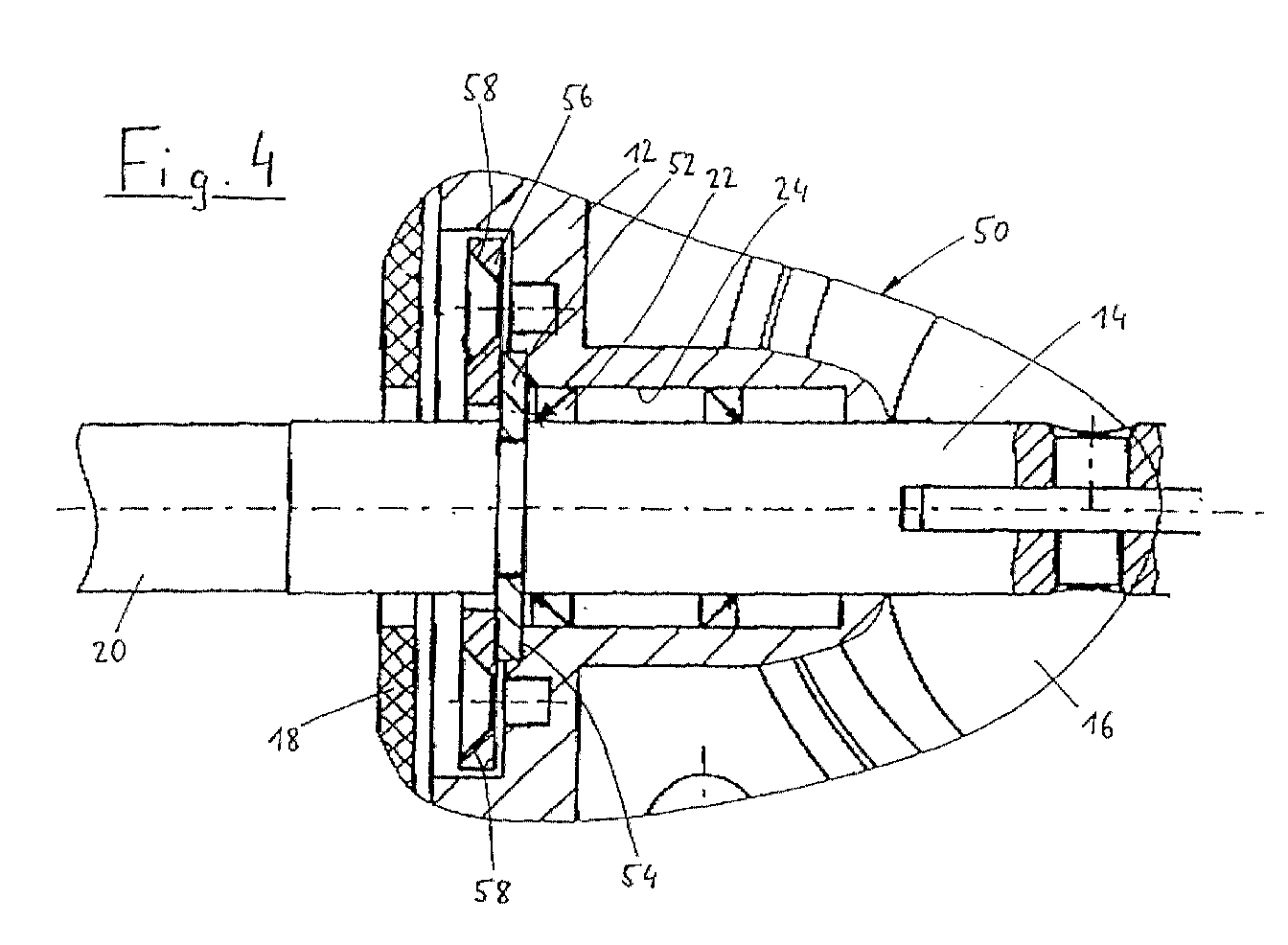
Bei einem Drosselklappenstutzen mit Torquer-Antrieb sitzt der Rotor des
Antriebsmotors unmittelbar auf der Welle (14) der Drosselklappe (16). Um
bei einfacher Montage eine dauerhafte Axialsicherung der Welle zu
erreichen, ist der Rotor auf die Welle (14) aufgepreßt, wobei zwischen der
Drosselklappe (16) und dem Rotor eine Sicherungsscheibe (52) vorgesehen
ist, die an der Welle (14) oder an einem Drosselklappengehäuse (12)
axial festgelegt ist und an dem jeweils anderen Element mit bestimmtem
Axialspiel in einen Spalt (32) eingreift, und die beiden gehäuseseitigen
axialen Anlageflächen der Sicherungsscheibe (52) durch ein mit dem
Gehäuse (12) verschraubtes Befestigungsblech (56) und einen am
Gehäuse (12) vorgesehenen Anschlag (54) gebildet sind. Die schmale
Axialsicherung erlaubt eine rotorseitige Anordnung zur Montagevereinfachung
bei gleichzeitig kurzer und steifer Drosselklappenwelle (14).
Applications Claiming Priority (4)
| Application Number | Priority Date | Filing Date | Title |
|---|---|---|---|
| DE19932881 | 1999-07-16 | ||
| DE19932878 | 1999-07-16 | ||
| DE19932881 | 1999-07-16 | ||
| DE19932878 | 1999-07-16 |
Publications (3)
| Publication Number | Publication Date |
|---|---|
| EP1069352A2 EP1069352A2 (en) | 2001-01-17 |
| EP1069352A3 true EP1069352A3 (en) | 2002-08-14 |
| EP1069352B1 EP1069352B1 (en) | 2003-05-21 |
Family
ID=26054180
Family Applications (1)
| Application Number | Title | Priority Date | Filing Date |
|---|---|---|---|
| EP99118842A Expired - Lifetime EP1069352B1 (en) | 1999-07-16 | 1999-09-24 | Throttle valve support |
Country Status (4)
| Country | Link |
|---|---|
| US (1) | US6416035B1 (en) |
| EP (1) | EP1069352B1 (en) |
| JP (1) | JP2001041059A (en) |
| DE (1) | DE59905651D1 (en) |
Families Citing this family (1)
| Publication number | Priority date | Publication date | Assignee | Title |
|---|---|---|---|---|
| DE102018204431B4 (en) * | 2018-03-22 | 2020-06-04 | smk systeme metall kunststoff gmbh & co. kg | Vibration-optimized flap valve and exhaust flap system with such a flap valve |
Citations (4)
| Publication number | Priority date | Publication date | Assignee | Title |
|---|---|---|---|---|
| DE3924611A1 (en) * | 1989-07-26 | 1991-01-31 | Vdo Schindling | THROTTLE VALVE CONNECTOR |
| DE4017671A1 (en) * | 1990-04-05 | 1991-10-10 | Vdo Schindling | GAME-FREE AND TURN-proof connection |
| JPH04183940A (en) * | 1990-11-16 | 1992-06-30 | Hitachi Ltd | Vacuum control valve for internal combustion engine |
| JPH10227233A (en) * | 1997-02-13 | 1998-08-25 | Unisia Jecs Corp | Negative pressure control valve device for internal combustion engine |
Family Cites Families (8)
| Publication number | Priority date | Publication date | Assignee | Title |
|---|---|---|---|---|
| USRE34906E (en) * | 1986-06-02 | 1995-04-18 | Hitachi, Ltd. | Motor-driven throttle valve assembly |
| GB8912537D0 (en) * | 1989-06-01 | 1989-07-19 | Lucas Ind Plc | Throttle actuator and control system |
| DE4026785A1 (en) * | 1990-08-24 | 1992-02-27 | Bosch Gmbh Robert | ACTUATOR |
| JPH07324636A (en) * | 1994-04-04 | 1995-12-12 | Nippondenso Co Ltd | Throttle valve controller |
| DE69627401T3 (en) * | 1995-01-17 | 2014-01-30 | Hitachi, Ltd. | Airflow control device |
| JPH10288054A (en) * | 1997-02-13 | 1998-10-27 | Denso Corp | Throttle valve control device |
| US6079210A (en) * | 1998-07-16 | 2000-06-27 | Woodward Governor Company | Continuously variable electrically actuated flow control valve for high temperature applications |
| US6244565B1 (en) * | 1999-01-29 | 2001-06-12 | Ford Global Technologies, Inc. | Throttle body shaft axial play control |
-
1999
- 1999-09-24 DE DE59905651T patent/DE59905651D1/en not_active Expired - Lifetime
- 1999-09-24 EP EP99118842A patent/EP1069352B1/en not_active Expired - Lifetime
-
2000
- 2000-07-13 JP JP2000213194A patent/JP2001041059A/en active Pending
- 2000-07-13 US US09/615,913 patent/US6416035B1/en not_active Expired - Fee Related
Patent Citations (4)
| Publication number | Priority date | Publication date | Assignee | Title |
|---|---|---|---|---|
| DE3924611A1 (en) * | 1989-07-26 | 1991-01-31 | Vdo Schindling | THROTTLE VALVE CONNECTOR |
| DE4017671A1 (en) * | 1990-04-05 | 1991-10-10 | Vdo Schindling | GAME-FREE AND TURN-proof connection |
| JPH04183940A (en) * | 1990-11-16 | 1992-06-30 | Hitachi Ltd | Vacuum control valve for internal combustion engine |
| JPH10227233A (en) * | 1997-02-13 | 1998-08-25 | Unisia Jecs Corp | Negative pressure control valve device for internal combustion engine |
Non-Patent Citations (2)
| Title |
|---|
| PATENT ABSTRACTS OF JAPAN vol. 016, no. 498 (M - 1325) 15 October 1992 (1992-10-15) * |
| PATENT ABSTRACTS OF JAPAN vol. 1998, no. 13 30 November 1998 (1998-11-30) * |
Also Published As
| Publication number | Publication date |
|---|---|
| EP1069352A2 (en) | 2001-01-17 |
| DE59905651D1 (en) | 2003-06-26 |
| US6416035B1 (en) | 2002-07-09 |
| EP1069352B1 (en) | 2003-05-21 |
| JP2001041059A (en) | 2001-02-13 |
Similar Documents
| Publication | Publication Date | Title |
|---|---|---|
| DE3327453A1 (en) | FUEL GEAR PUMP | |
| DE4415031C1 (en) | Hydrodynamic device as a heating generator for a motor vehicle | |
| EP3232065B1 (en) | Pump motor with a fixed bearing | |
| EP1474611B1 (en) | Liquid pump | |
| EP3646436A1 (en) | Electric motor | |
| JPH10500649A (en) | Drive unit having an electrical drive motor and a worm transmission downstream of the drive motor | |
| WO1999040669A1 (en) | Electrical motor | |
| DE9108745U1 (en) | Electric motor, in particular small motor for auxiliary motor vehicles | |
| DE3123579C2 (en) | ||
| EP1353067B1 (en) | Motor pump unit | |
| DE102023212524A1 (en) | Side channel compressor for a fuel cell system for conveying and/or compressing a gaseous medium, fuel cell system | |
| EP0797004B1 (en) | Electric motor driven air pump | |
| EP1069352A3 (en) | Throttle valve support | |
| DE102009055614B4 (en) | Turbocharger with a plastic compressor housing | |
| WO2001081769A1 (en) | Feed pump | |
| DE102019118708A1 (en) | Pressure supply device with a gear pump | |
| DE102015216653A1 (en) | Gearbox housing and gearbox drive unit | |
| EP1045149A2 (en) | Coolant pump | |
| WO1998007986A1 (en) | Electromotor/pump assembly | |
| DE10242570A1 (en) | Axial force transfer device for drive shaft e.g. of electric motor, has elements with opening for first shaft section, and at least one annular counter surface protruding beyond first shaft section and enclosing shaft axis | |
| EP1925797B1 (en) | Actuating drive for an actuator | |
| EP1792806B1 (en) | Steering angle sensor | |
| EP1580869B1 (en) | Resolver and its fixing on an electric machine | |
| DE4224847A1 (en) | Fuel delivery device | |
| EP3482047B1 (en) | Automotive auxiliary assembly vacuum pump having a single-piece flange element |
Legal Events
| Date | Code | Title | Description |
|---|---|---|---|
| PUAI | Public reference made under article 153(3) epc to a published international application that has entered the european phase |
Free format text: ORIGINAL CODE: 0009012 |
|
| AK | Designated contracting states |
Kind code of ref document: A2 Designated state(s): AT BE CH CY DE DK ES FI FR GB GR IE IT LI LU MC NL PT SE |
|
| AX | Request for extension of the european patent |
Free format text: AL;LT;LV;MK;RO;SI |
|
| RAP1 | Party data changed (applicant data changed or rights of an application transferred) |
Owner name: SIEMENS AKTIENGESELLSCHAFT |
|
| PUAL | Search report despatched |
Free format text: ORIGINAL CODE: 0009013 |
|
| AK | Designated contracting states |
Kind code of ref document: A3 Designated state(s): AT BE CH CY DE DK ES FI FR GB GR IE IT LI LU MC NL PT SE |
|
| AX | Request for extension of the european patent |
Free format text: AL;LT;LV;MK;RO;SI |
|
| RIC1 | Information provided on ipc code assigned before grant |
Free format text: 7F 16K 1/22 A, 7F 02D 9/10 B |
|
| 17P | Request for examination filed |
Effective date: 20020905 |
|
| GRAH | Despatch of communication of intention to grant a patent |
Free format text: ORIGINAL CODE: EPIDOS IGRA |
|
| GRAH | Despatch of communication of intention to grant a patent |
Free format text: ORIGINAL CODE: EPIDOS IGRA |
|
| GRAA | (expected) grant |
Free format text: ORIGINAL CODE: 0009210 |
|
| AKX | Designation fees paid |
Designated state(s): AT BE CH CY DE DK ES FI FR GB GR IE IT LI LU MC NL PT SE |
|
| RBV | Designated contracting states (corrected) |
Designated state(s): DE FR GB IT |
|
| AK | Designated contracting states |
Designated state(s): DE FR GB IT |
|
| REG | Reference to a national code |
Ref country code: GB Ref legal event code: FG4D Free format text: NOT ENGLISH |
|
| REG | Reference to a national code |
Ref country code: IE Ref legal event code: FG4D Free format text: GERMAN |
|
| REF | Corresponds to: |
Ref document number: 59905651 Country of ref document: DE Date of ref document: 20030626 Kind code of ref document: P |
|
| GBT | Gb: translation of ep patent filed (gb section 77(6)(a)/1977) | ||
| REG | Reference to a national code |
Ref country code: IE Ref legal event code: FD4D Ref document number: 1069352E Country of ref document: IE |
|
| ET | Fr: translation filed | ||
| PLBE | No opposition filed within time limit |
Free format text: ORIGINAL CODE: 0009261 |
|
| STAA | Information on the status of an ep patent application or granted ep patent |
Free format text: STATUS: NO OPPOSITION FILED WITHIN TIME LIMIT |
|
| 26N | No opposition filed |
Effective date: 20040224 |
|
| PGFP | Annual fee paid to national office [announced via postgrant information from national office to epo] |
Ref country code: GB Payment date: 20040907 Year of fee payment: 6 |
|
| PGFP | Annual fee paid to national office [announced via postgrant information from national office to epo] |
Ref country code: FR Payment date: 20040921 Year of fee payment: 6 |
|
| PG25 | Lapsed in a contracting state [announced via postgrant information from national office to epo] |
Ref country code: IT Free format text: LAPSE BECAUSE OF NON-PAYMENT OF DUE FEES Effective date: 20050924 Ref country code: GB Free format text: LAPSE BECAUSE OF NON-PAYMENT OF DUE FEES Effective date: 20050924 |
|
| GBPC | Gb: european patent ceased through non-payment of renewal fee |
Effective date: 20050924 |
|
| PG25 | Lapsed in a contracting state [announced via postgrant information from national office to epo] |
Ref country code: FR Free format text: LAPSE BECAUSE OF NON-PAYMENT OF DUE FEES Effective date: 20060531 |
|
| REG | Reference to a national code |
Ref country code: FR Ref legal event code: ST Effective date: 20060531 |
|
| PGFP | Annual fee paid to national office [announced via postgrant information from national office to epo] |
Ref country code: DE Payment date: 20120930 Year of fee payment: 14 |
|
| REG | Reference to a national code |
Ref country code: DE Ref legal event code: R119 Ref document number: 59905651 Country of ref document: DE Effective date: 20140401 |
|
| PG25 | Lapsed in a contracting state [announced via postgrant information from national office to epo] |
Ref country code: DE Free format text: LAPSE BECAUSE OF NON-PAYMENT OF DUE FEES Effective date: 20140401 |