EP1069352A2 - Throttle valve support - Google Patents
Throttle valve support Download PDFInfo
- Publication number
- EP1069352A2 EP1069352A2 EP99118842A EP99118842A EP1069352A2 EP 1069352 A2 EP1069352 A2 EP 1069352A2 EP 99118842 A EP99118842 A EP 99118842A EP 99118842 A EP99118842 A EP 99118842A EP 1069352 A2 EP1069352 A2 EP 1069352A2
- Authority
- EP
- European Patent Office
- Prior art keywords
- throttle valve
- shaft
- housing
- axial
- rotor
- Prior art date
- Legal status (The legal status is an assumption and is not a legal conclusion. Google has not performed a legal analysis and makes no representation as to the accuracy of the status listed.)
- Granted
Links
Images


Classifications
-
- F—MECHANICAL ENGINEERING; LIGHTING; HEATING; WEAPONS; BLASTING
- F16—ENGINEERING ELEMENTS AND UNITS; GENERAL MEASURES FOR PRODUCING AND MAINTAINING EFFECTIVE FUNCTIONING OF MACHINES OR INSTALLATIONS; THERMAL INSULATION IN GENERAL
- F16K—VALVES; TAPS; COCKS; ACTUATING-FLOATS; DEVICES FOR VENTING OR AERATING
- F16K1/00—Lift valves or globe valves, i.e. cut-off apparatus with closure members having at least a component of their opening and closing motion perpendicular to the closing faces
- F16K1/16—Lift valves or globe valves, i.e. cut-off apparatus with closure members having at least a component of their opening and closing motion perpendicular to the closing faces with pivoted closure-members
- F16K1/18—Lift valves or globe valves, i.e. cut-off apparatus with closure members having at least a component of their opening and closing motion perpendicular to the closing faces with pivoted closure-members with pivoted discs or flaps
- F16K1/22—Lift valves or globe valves, i.e. cut-off apparatus with closure members having at least a component of their opening and closing motion perpendicular to the closing faces with pivoted closure-members with pivoted discs or flaps with axis of rotation crossing the valve member, e.g. butterfly valves
-
- F—MECHANICAL ENGINEERING; LIGHTING; HEATING; WEAPONS; BLASTING
- F02—COMBUSTION ENGINES; HOT-GAS OR COMBUSTION-PRODUCT ENGINE PLANTS
- F02D—CONTROLLING COMBUSTION ENGINES
- F02D9/00—Controlling engines by throttling air or fuel-and-air induction conduits or exhaust conduits
- F02D9/08—Throttle valves specially adapted therefor; Arrangements of such valves in conduits
- F02D9/10—Throttle valves specially adapted therefor; Arrangements of such valves in conduits having pivotally-mounted flaps
- F02D9/1035—Details of the valve housing
- F02D9/106—Sealing of the valve shaft in the housing, e.g. details of the bearings
-
- F—MECHANICAL ENGINEERING; LIGHTING; HEATING; WEAPONS; BLASTING
- F02—COMBUSTION ENGINES; HOT-GAS OR COMBUSTION-PRODUCT ENGINE PLANTS
- F02D—CONTROLLING COMBUSTION ENGINES
- F02D9/00—Controlling engines by throttling air or fuel-and-air induction conduits or exhaust conduits
- F02D9/08—Throttle valves specially adapted therefor; Arrangements of such valves in conduits
- F02D9/10—Throttle valves specially adapted therefor; Arrangements of such valves in conduits having pivotally-mounted flaps
- F02D9/107—Manufacturing or mounting details
Definitions
- the invention relates to a throttle valve connector with a Torquer drive, in which the rotor of an electric drive motor directly sits on the throttle valve shaft.
- the invention further relates to a method for mounting such a throttle valve assembly.
- the object of the present invention is an axial securing for a throttle body with Torquer drive to create the withstands the higher loads and is easy to assemble.
- the object is achieved by a throttle valve connector solved with Torquer drive, in which the rotor of an electric Drive motor pressed directly onto the shaft of the throttle valve is, with an axial lock between the throttle valve and the rotor is provided in the form of a locking washer on the shaft or on a throttle body is axially fixed and on each engages another element in a gap with a defined axial play, and the two axial contact surfaces of the locking washer on the housing through a mounting plate screwed to the housing and a provided on the housing stop are formed.
- the solution of the invention offers the advantage that the Lock washer a large area on the two flanks of the Creates gap, so that despite the increased mass forces by the on the Throttle valve seated rotor of the electric motor the wing load and so the wear and tear is low, which means a lifetime constant axial play is ensured.
- the axial housing-side fixing with the help of a screwed Fastening plates also ensure that only a very small one is required axial space, which the advantageous arrangement for assembly reasons Axial locking between the throttle valve and the rotor at short and making rigid throttle valve shaft possible.
- the locking washer can be designed, for example, as a C washer and can be inserted laterally into the groove or by means of two half shells be realized.
- the mounting plate and the locking washer be formed in one piece, the shaft opening being in the form of a keyhole is trained.
- the advantage of this embodiment is again somewhat less axial space and in the reduction of parts.
- the extended area of the keyhole serves to insert the Shaft before assembly in the throttle body. Also an open one Formation of the keyhole opening is conceivable.
- the locking washer is fixed axially on the shaft circumference and the gap on Housing through an axial stop and a flank of the mounting plate is defined.
- the axial stop can be done with a running disk be provided.
- the axial play in this variant results from the difference between the axial distance of the housing stop from the contact surface of the Mounting plate and the thickness of the lock washer.
- the tight fit the lock washer on the throttle valve shaft is preferred made with the help of a welded joint, in principle also a press connection is possible, but under certain circumstances a stronger lock washer required to ensure a secure fit to ensure the disc on the shaft.
- the present invention also relates to a method for Installation of a throttle body of the type described above. According to the invention it is provided that the throttle valve neck is completely pre-assembled and only before the Close the throttle body of the rotor on the shaft is pressed on.
- the throttle body 10 shown in Fig. 1 consists essentially from a throttle valve housing 12, one mounted in this Throttle valve shaft 14, which carries the throttle valve 16, one Potentiometer, of which only the one fixed and centered on the housing side Potentiometer plate 18 is shown, and a rotor (not shown) of an electric drive motor that directly on a Fit area 20 can be pressed onto the free end of the shaft 14.
- the Housing is in the area of the drive motor through a cover (not shown) closable.
- the shaft 14 is supported in the housing 12 on both sides the throttle valve 16 by means of a needle bearing 22, for example from a directly in a housing bore 24 and on the shaft 14 running needle sleeve can exist.
- a locking washer 26 is provided (see also FIG. 2 or 3), which have a keyhole-shaped opening 28 has the edge 30 in the narrow area with a circumferential groove 32 in the shaft 14 cooperates.
- the width of the circumferential groove 32 is related to the thickness of the locking washer 26 so chosen that the desired Axial play results.
- the axial position of the shaft 14 is determined by a defines housing-side contact surface 34 against which the locking washer 26 can be screwed with the aid of screws (not shown). As Screws are suitable because of the small thickness of the lock washer 26 countersunk screws, the necessary over tapered holes 36 Holding forces can be transferred to the locking washer 26.
- Fig. 3 shown variant of a locking washer 38 with one side open keyhole opening 40 conceivable.
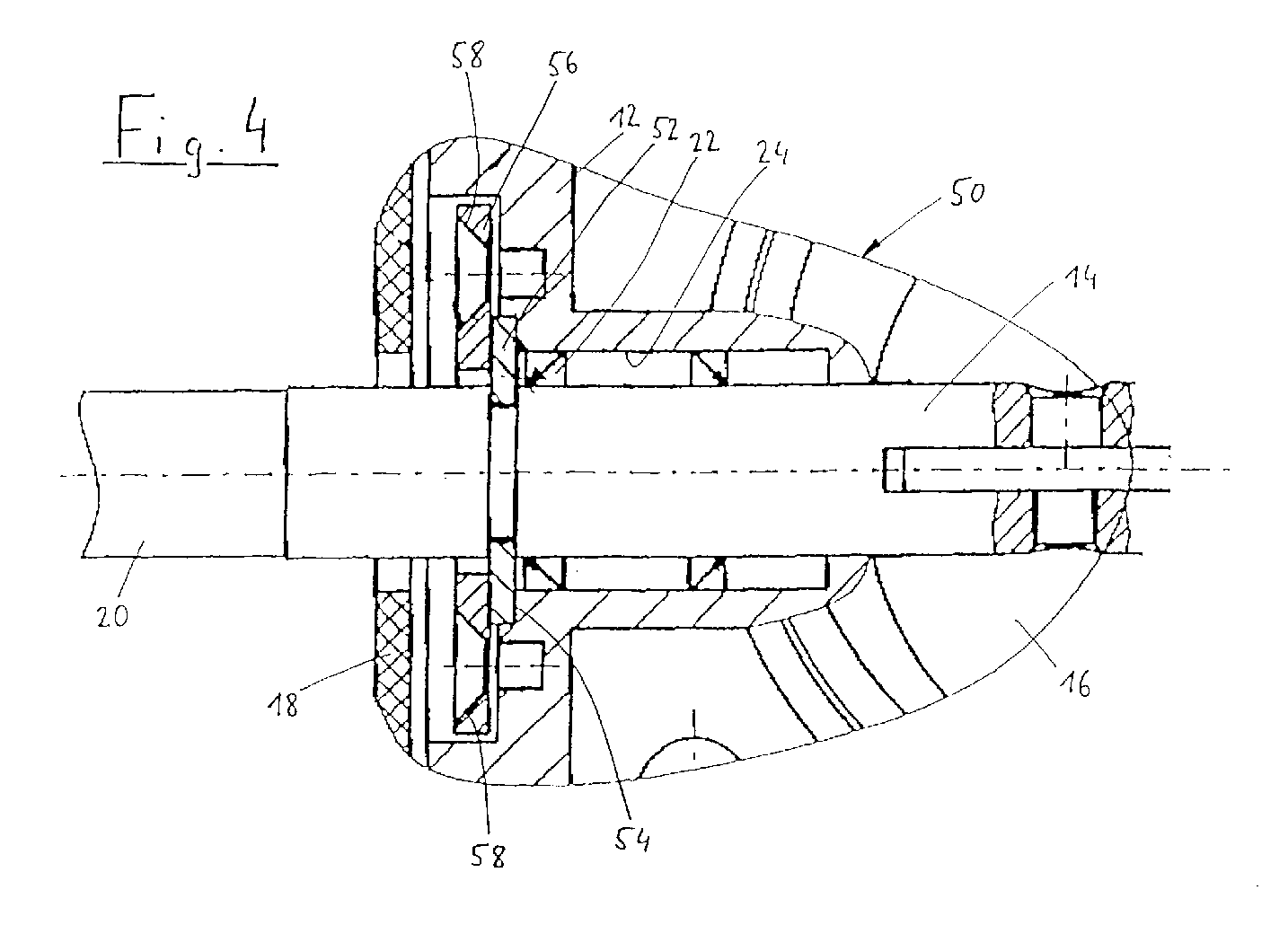
- FIG. 4 Another embodiment of a throttle valve assembly 50 is shown in FIG. 4 shown. With the exception of the axial lock, this corresponds to the throttle valve assembly 50 the previously described throttle valve connector 10, which is why identical parts are provided with identical reference numerals.
- the throttle valve assembly 50 has a lock washer 52 in C-shape on (Figure 5a), in the circumferential groove 32 of the shaft 14 sits.
- the locking washer 52 is axially supported on a housing shoulder 54, which defines the position of the shaft with respect to the housing 12.
- the locking washer 52 is axially fixed with the aid of a Mounting plate 56, which in turn with the help of countersunk screws (not shown) on tapered bores 58 in the mounting plate 56 act against the housing 12 is screwed.
- the lock washer 52 between the shoulder 54 and the mounting plate 56 tense.
- the locking washer can also consist of two Half shells 52a, 52b may be formed. ( Figure 5b)
- the mounting plate 56 is shown in FIG. 6. It essentially exists from an annular holding area 59, the inner diameter larger than the outer diameter of the shaft, but smaller than that Outside diameter of the C-shaped locking washer 52 is. To the Ring area 59 adjoin two bore areas 60, in which the tapered bores 58 are arranged.
- FIG. 7 Another variant of a throttle valve assembly 80 is shown in FIG. 7 shown.
- This throttle valve neck there is no axial play between a lock washer 82 and a circumferential groove in the shaft 14 provided, but the axial play results from the housing side Difference in the width of a gap 84 to the thickness of the lock washer 82, which is welded onto the outer circumference of the shaft 14 as a simple ring is.
- the gap 84 is delimited by a on a housing shoulder 86 provided runner 88 and a mounting plate 90, the is screwed to a contact surface 92 on the housing 12.
- Fig. 8 shows a modification of the throttle body 80, in which a somewhat stronger lock washer 94 is provided, the tight fit on shaft 14 not with the help of a welded joint but is guaranteed by a press connection.
- the fastening element 90 corresponds to that in FIG. 7 as well the embodiment of the throttle valve assembly 80 shown in FIG 6 mounting plate 56 shown in FIG. 6, but not is used to clamp the locking washer, but only an axial stop surface with a corresponding displacement of the shaft 14 forms.
- the potentiometer plates 18 are in all of the previously described embodiments axially close to the needle bearings 22 on the housing 12 fastened and centered, which is due to the small axial installation space demanding axial locks is possible.
- the proximity of the potentiometer to the storage ensures only low amplitudes with vibrations excited shaft 14, so that an accurate actual value acquisition is possible.
- the throttle body 10, 50, 80 is installed in such a way that first the shaft 14 is inserted into the bearing 22 in the housing 12 becomes.
- the locking washer 26, 52 or 82 is already seated on the shaft 14 and limits the axial insertion by placing on the Contact surface 34, the housing shoulder 54 or the running disk 88.
- the throttle valve 16 is mounted and the shaft through Screw the locking washer 26 or the fastener 56 or 90 axially fixed.
- the next step is the potentiometer plate 18 centered on the housing 12.
- the associated grinder can then be set on the shaft.
- the rotor of the drive motor is pressed onto the socket 20 and that Housing closed with a lid.
Landscapes
- Engineering & Computer Science (AREA)
- General Engineering & Computer Science (AREA)
- Mechanical Engineering (AREA)
- Chemical & Material Sciences (AREA)
- Combustion & Propulsion (AREA)
- Control Of Throttle Valves Provided In The Intake System Or In The Exhaust System (AREA)
Abstract
Bei einem Drosselklappenstutzen mit Torquer-Antrieb sitzt der Rotor des
Antriebsmotors unmittelbar auf der Welle (14) der Drosselklappe (16). Um
bei einfacher Montage eine dauerhafte Axialsicherung der Welle zu
erreichen, ist der Rotor auf die Welle (14) aufgepreßt, wobei zwischen der
Drosselklappe (16) und dem Rotor eine Sicherungsscheibe (52) vorgesehen
ist, die an der Welle (14) oder an einem Drosselklappengehäuse (12)
axial festgelegt ist und an dem jeweils anderen Element mit bestimmtem
Axialspiel in einen Spalt (32) eingreift, und die beiden gehäuseseitigen
axialen Anlageflächen der Sicherungsscheibe (52) durch ein mit dem
Gehäuse (12) verschraubtes Befestigungsblech (56) und einen am
Gehäuse (12) vorgesehenen Anschlag (54) gebildet sind. Die schmale
Axialsicherung erlaubt eine rotorseitige Anordnung zur Montagevereinfachung
bei gleichzeitig kurzer und steifer Drosselklappenwelle (14).
Description
Die Erfindung befaßt sich mit einem Drosselklappenstutzen mit Torquer-Antrieb, bei welchem der Rotor eines elektrischen Antriebsmotors unmittelbar auf der Welle der Drosselklappe sitzt. Die Erfindung betrifft weiterhin ein Verfahren zur Montage eines solchen Drosselklappenstutzens.The invention relates to a throttle valve connector with a Torquer drive, in which the rotor of an electric drive motor directly sits on the throttle valve shaft. The invention further relates to a method for mounting such a throttle valve assembly.
Eine derartige Anordnung des Rotors kommt im Vergleich zu über Getriebestufen mit der Drosselklappenwelle gekoppelten Motoren mit sehr wenigen Bauteilen aus und benötigt auch nur einen geringeren Bauraum. Zu berücksichtigen ist allerdings, daß die Drosselklappe zu Schwingungen angeregt wird. Während bei Lösungen mit separat gelagertem Rotor ein im Gehäuse des Drosselklappenstutzens verankerter Stift, der in eine Umfangsnut an der Drosseklappenwelle mit bestimmtem Spiel eingreift, zur axialen Sicherung der Welle ausreichend sein kann, führt die hohe Masse des Rotors bei einem Drosselklappenstutzen mit Torquer-Antrieb unter den Schwingbewegungen zu einer sehr großen Flächenbelastung, so daß es bei kleinen Stützflächen schnell zu einem Verschleiß der axialen Anlageflächen und damit zu einem Anstieg des Axialspiels kommen kann. Die Drosselklappe wird schwergängiger und kann im extremsten Fall verklemmen. Als weiteres Problem bei der axialen Festlegung der Drosselklappenwelle kommt hinzu, daß nur ein begrenzter axialer Bauraum zur Verfügung steht, da neben der Axialsicherung und dem Rotor auch noch ein Potentiometer zur Erfaßung der Iststellung der Drosselklappe und die Wälzlager zur Lagerung der Drosselklappenwelle in dem Drosselklappengehäuse vorgesehen werden muß. Es ist zwar grundsätzlich möglich, diese Elemente zu beiden Seiten der Drosselklappe im Gehäuse anzuordnen, wodurch jedoch der Montageablauf erschwert wird.Such an arrangement of the rotor is compared to Gear stages with engines coupled with the throttle valve shaft few components and also requires less space. However, it must be taken into account that the throttle valve vibrates is excited. While in solutions with a separately stored rotor pin anchored in the housing of the throttle valve body, which in a Circumferential groove on the throttle valve shaft engages with certain play, may be sufficient to axially secure the shaft, the high Mass of the rotor in a throttle valve assembly with Torquer drive under the swinging movements to a very large wing load, so that it quickly wears the small support surfaces axial contact surfaces and thus an increase in the axial play can come. The throttle valve becomes sluggish and can in jam extreme case. Another problem with the axial Definition of the throttle valve shaft is added to that only a limited axial space is available because in addition to the axial securing and the rotor also has a potentiometer for detecting the actual position of the Throttle valve and the roller bearings for mounting the throttle valve shaft must be provided in the throttle body. It is basically possible, these elements on both sides of the throttle valve to be arranged in the housing, but this complicates the assembly process becomes.
Die Aufgabe der vorliegenden Erfindung besteht darin, eine Axialsicherung für einen Drosselklappenstutzen mit Torquer-Antrieb zu schaffen, die den höheren Beanspruchungen standhält und einfach zu montieren ist.The object of the present invention is an axial securing for a throttle body with Torquer drive to create the withstands the higher loads and is easy to assemble.
Erfindungsgemäß wird die Aufgabe durch einen Drosselklappenstutzen mit Torquer-Antrieb gelöst, bei welchem der Rotor eines elektrischen Antriebsmotors unmittelbar auf die Welle der Drosselklappe aufgepreßt ist, wobei zwischen der Drosselklappe und dem Rotor eine Axialsicherung in Form einer Sicherungsscheibe vorgesehen ist, die an der Welle oder an einem Drosselklappengehäuse axial festgelegt ist und an dem jeweils anderen Element in einen Spalt mit definiertem Axialspiel eingreift, und die beiden gehäuseseitigen axialen Anlageflächen der Sicherungsscheibe durch ein mit dem Gehäuse verschraubtes Befestigungsblech und einen am Gehäuse vorgesehenen Anschlag gebildet sind.According to the invention, the object is achieved by a throttle valve connector solved with Torquer drive, in which the rotor of an electric Drive motor pressed directly onto the shaft of the throttle valve is, with an axial lock between the throttle valve and the rotor is provided in the form of a locking washer on the shaft or on a throttle body is axially fixed and on each engages another element in a gap with a defined axial play, and the two axial contact surfaces of the locking washer on the housing through a mounting plate screwed to the housing and a provided on the housing stop are formed.
Die erfindungsgemäße Lösung bietet zunächst den Vorteil, daß die Sicherungsscheibe eine großflächige Anlage an den beiden Flanken des Spaltes schafft, so daß trotz der erhöhten Massenkräfte durch den auf der Drosselklappenwelle sitzenden Rotor des Elektromotores die Flächenbelastung und damit der Verschleiß gering ist, wodurch ein über die Lebensdauer konstantes Axialspiel sichergestellt wird.The solution of the invention offers the advantage that the Lock washer a large area on the two flanks of the Creates gap, so that despite the increased mass forces by the on the Throttle valve seated rotor of the electric motor the wing load and so the wear and tear is low, which means a lifetime constant axial play is ensured.
Die axiale gehäuseseitige Festlegung mit Hilfe eines verschraubten Befestigungsbleches sorgt zudem für einen nur sehr kleinen notwendigen axialen Bauraum, der die aus Montagegründen vorteilhafte Anordnung der Axialsicherung zwischen der Drosselklappe und dem Rotor bei kurzer und damit steifer Drosselklappenwelle möglich macht.The axial housing-side fixing with the help of a screwed Fastening plates also ensure that only a very small one is required axial space, which the advantageous arrangement for assembly reasons Axial locking between the throttle valve and the rotor at short and making rigid throttle valve shaft possible.
In einer ersten bevorzugten Ausführungsform der Erfindung ist vorgesehen, daß die Sicherungsscheibe unter bestimmtem Axialspiel in einer Umfangsnut auf der Welle sitzt und gehäuseseitig mit Hilfe des Befestigungsbleches axial spielfrei festgelegt ist.In a first preferred embodiment of the invention, that the locking washer with a certain axial play in one The circumferential groove sits on the shaft and on the housing side with the help of the mounting plate is set axially without play.
Bei dieser Ausführungsform läßt sich das Axialspiel mit geringem fertigungstechnischem Aufwand sehr genau einhalten, da bei bekannter Stärke der Sicherungsscheibe lediglich eine Umfangsnut mit bestimmter Breite in den Umfang der Drosselklappenwelle eingestochen werden muß. Die Sicherungsscheibe kann beispielsweise als C-Scheibe ausgebildet und seitlich in die Nut einschiebbar oder mittels zweier Halbschalen realisiert sein.In this embodiment, the axial play with little manufacturing technology Adhere to the effort very precisely, as with known ones Strength of the locking washer only a circumferential groove with a certain Width must be inserted into the circumference of the throttle valve shaft. The locking washer can be designed, for example, as a C washer and can be inserted laterally into the groove or by means of two half shells be realized.
Weiterhin können das Befestigungsblech und die Sicherungsscheibe einstückig ausgebildet sein, wobei die Wellenöffnung schlüssellochförmig ausgebildet ist. Der Vorteil dieser Ausführungsform liegt in dem nochmals etwas geringeren axialen Bauraum und in der Verringerung der Teile. Der erweiterte Bereich des Schlüsselloches dient dabei dem Einführen der Welle vor der Montage in dem Drosselklappengehäuse. Auch eine offene Ausbildung der Schlüssellochöffnung ist denkbar.Furthermore, the mounting plate and the locking washer be formed in one piece, the shaft opening being in the form of a keyhole is trained. The advantage of this embodiment is again somewhat less axial space and in the reduction of parts. The extended area of the keyhole serves to insert the Shaft before assembly in the throttle body. Also an open one Formation of the keyhole opening is conceivable.
Als Alternative zu einer in der Welle vorgesehenen Umfangsnut ist in einer weiteren Ausführungsform der Erfindung vorgesehen, daß die Sicherungsscheibe axial am Wellenumfang festgelegt ist und der Spalt am Gehäuse durch einen axialen Anschlag und eine Flanke des Befestigungsbleches definiert ist. Der axiale Anschlag kann mit einer Laufscheibe versehen sein. As an alternative to a circumferential groove provided in the shaft is in a Another embodiment of the invention provided that the locking washer is fixed axially on the shaft circumference and the gap on Housing through an axial stop and a flank of the mounting plate is defined. The axial stop can be done with a running disk be provided.
Das Axialspiel ergibt sich bei dieser Variante aus der Differenz zwischen dem axialen Abstand des Gehäuseanschlags von der Anlagefläche des Befestigungsbleches und der Dicke der Sicherungsscheibe. Der feste Sitz der Sicherungsscheibe auf der Drosselklappenwelle wird vorzugsweise mit Hilfe einer Schweißverbindung hergestellt, wobei grundsätzlich auch eine Preßverbindung möglich ist, die unter Umständen jedoch eine stärkere Sicherungsscheibe erforderlich macht, um einen sicheren Sitz der Scheibe auf der Welle zu gewährleisten.The axial play in this variant results from the difference between the axial distance of the housing stop from the contact surface of the Mounting plate and the thickness of the lock washer. The tight fit the lock washer on the throttle valve shaft is preferred made with the help of a welded joint, in principle also a press connection is possible, but under certain circumstances a stronger lock washer required to ensure a secure fit to ensure the disc on the shaft.
Gegenstand der vorliegenden Erfindung ist auch eine Verfahren zur Montage eines Drosselklappenstutzens der zuvor beschriebenen Art. Erfindungsgemäß ist dabei vorgesehen, daß zunächst der Drosselklappenstutzen vollständig vormontiert wird und erst abschließend vor dem Verschließen des Drosselklappengehäuses der Rotor auf die Welle aufgepreßt wird.The present invention also relates to a method for Installation of a throttle body of the type described above. According to the invention it is provided that the throttle valve neck is completely pre-assembled and only before the Close the throttle body of the rotor on the shaft is pressed on.
Der Vorteil dieses Montageverfahrens liegt darin, daß die Drosselklappenwelle von der Rotorseite in die meist als Nadellager ausgebildeten Lager eingeschoben werden kann und anschließend ohne Behinderung durch den Rotor die Axialsicherung und das Potentiometer montiert werden können. Das hohe Gewicht des Rotors würde ferner die Handhabung bei der Montage erschweren.The advantage of this assembly process is that the throttle valve shaft from the rotor side into the mostly designed as needle bearings Bearing can be inserted and then without hindrance the axial lock and the potentiometer are mounted by the rotor can be. The heavy weight of the rotor would also make handling complicate assembly.
Nachfolgend wird anhand der beigefügten Zeichnungen näher auf Ausführungsbeispiele der Erfindung eingegangen. Es zeigen:
- Fig. 1
- einen Querschnitt eines Drosselklappenstutzens;
- Fig. 2
- eine Ansicht der Axialsicherung der Drosselklappenwelle gemäß Fig. 1;
- Fig. 3
- eine alternative Axialsicherung der Drosselklappenwelle gemäß Fig. 1;
- Fig. 4
- einen Querschnitt einer weiteren Ausführungsform eines Drosselklappenstutzens;
- Fig. 5a
- eine erste Ansicht der Axial-Sicherungsscheibe für die Drosselklappenwelle gemäß Fig. 4;
- Fig. 5b
- eine zweite Ansicht der Axial-Sicherungsscheibe für die Drosselklappenwelle gemäß Fig. 4;
- Fig. 6
- eine Ansicht des Befestigungsbleches zur axialen Festlegung gemäß Fig. 4;
- Fig. 7
- einen Schnitt einer weiteren Ausführungsform eines Drosselklappenstutzens;
- Fig. 8
- eine modifizierte Ausführungsform des Drosselklappenstutzens nach Fig. 7.
- Fig. 1
- a cross section of a throttle valve assembly;
- Fig. 2
- a view of the axial securing of the throttle valve shaft according to FIG. 1;
- Fig. 3
- an alternative axial securing of the throttle valve shaft according to FIG. 1;
- Fig. 4
- a cross section of a further embodiment of a throttle valve assembly;
- Fig. 5a
- a first view of the axial locking washer for the throttle valve shaft according to FIG. 4;
- Fig. 5b
- a second view of the axial locking washer for the throttle valve shaft according to FIG. 4;
- Fig. 6
- a view of the mounting plate for axial fixing according to FIG. 4;
- Fig. 7
- a section of a further embodiment of a throttle valve assembly;
- Fig. 8
- 7 shows a modified embodiment of the throttle valve connector according to FIG. 7.
Der in Fig. 1 gezeigte Drosselklappenstutzen 10 besteht im wesentlichen
aus einem Drosselklappengehäuse 12, einer in diesem gelagerten
Drosselklappenwelle 14, welche die Drosselklappe 16 trägt, einem
Potentiometer, von welchem nur die gehäuseseitig befestigte und zentrierte
Potentiometerplatte 18 dargestellt ist, und einem Rotor (nicht
dargestellt) eines elektrischen Antriebsmotores, der unmittelbar auf einen
Passungsbereich 20 am freien Ende der Welle 14 aufpreßbar ist. Das
Gehäuse ist im Bereich des Antriebsmotors durch einen Deckel (nicht
dargestellt) verschließbar.The
Die Lagerung der Welle 14 in dem Gehäuse 12 erfolgt auf beiden Seiten
der Drosselklappe 16 mittels einer Nadellagerung 22, die beispielsweise
aus einer unmittelbar in einer Gehäusebohrung 24 und auf der Welle 14
laufenden Nadelhülse bestehen kann. Zur axialen Sicherung der Welle 14
bei definiertem Axialspiel ist eine Sicherungsscheibe 26 vorgesehen
(siehe auch Fig. 2 oder 3), die über eine schlüssellochförmige Öffnung 28
verfügt, deren Rand 30 im schmalen Bereich mit einer Umfangsnut 32 in
der Welle 14 zusammenwirkt. Die Breite der Umfangsnut 32 ist mit Bezug
auf die Dicke der Sicherungsscheibe 26 so gewählt, daß sich das gewünschte
Axialspiel ergibt. Die axiale Lage der Welle 14 wird durch eine
gehäuseseitige Anlagefläche 34 definiert, gegen welche die Sicherungsscheibe
26 mit Hilfe von Schrauben (nicht gezeigt) verschraubbar ist. Als
Schrauben eignen sich wegen der geringen Stärke der Sicherungsscheibe
26 Senkkopfschrauben, die über Kegelbohrungen 36 die notwendigen
Haltekräfte auf die Sicherungsscheibe 26 übertragen können.The
Neben der in Fig. 2 dargestellten Ausführungsform mit einer als geschlossenes
Schlüsselloch ausgebildeten Form der Öffnung ist auch eine in Fig.
3 dargestellte Variante einer Sicherungsscheibe 38 mit einer einseitig
offenen Schlüssellochöffnung 40 denkbar.In addition to the embodiment shown in Fig. 2 with a closed
Keyhole-shaped shape of the opening is also one in Fig.
3 shown variant of a locking
Eine weitere Ausführungsform eine Drosselklappenstutzens 50 ist in Fig. 4
dargestellt. Mit Ausnahme der Axialsicherung entspricht dieser Drosselklappenstutzen
50 dem zuvor beschriebenen Drosselklappenstutzen 10,
weshalb identische Teile mit identischen Bezugszeichen versehen sind. Another embodiment of a
Statt einer einstückigen, unmittelbar mit dem Gehäuse 12 verschraubten
Sicherungsscheibe weist der Drosselklappenstutzen 50 eine Sicherungsscheibe
52 in C-Form auf (Figur 5a), die in der Umfangsnut 32 der Welle
14 sitzt. Die Sicherungsscheibe 52 stützt sich axial an einem Gehäuseabsatz
54 ab, der die Lage der Welle bezüglich des Gehäuses 12 definiert.
Die axiale Festlegung der Sicherungsscheibe 52 erfolgt mit Hilfe eines
Befestigungsbleches 56, das wiederum mit Hilfe von Senkkopfschrauben
(nicht gezeigt), die auf Kegelbohrungen 58 in dem Befestigungsblech 56
wirken, gegen das Gehäuse 12 verschraubt wird. Dabei wird die Sicherungsscheibe
52 zwischen dem Absatz 54 und dem Befestigungsblech 56
verspannt. Die Sicherungsscheibe kann alternativ aber auch aus zwei
Halbschalen 52a, 52b gebildet sein. (Figur 5b)Instead of a one-piece, screwed directly to the
Das Befestigungsblech 56 ist in Fig. 6 dargestellt. Es besteht im wesentlichen
aus einem ringförmigen Haltebereich 59, dessen Innendurchmesser
größer als der Außendurchmesser der Welle, jedoch kleiner als der
Außendurchmesser der C-förmigen Sicherungsscheibe 52 ist. An den
Ringbereich 59 schließen sich zwei Bohrungsbereiche 60 an, in welchen
die Kegelbohrungen 58 angeordnet sind.The mounting
Eine weitere Variante eines Drosselklappenstutzens 80 ist in Fig. 7
gezeigt. Bei diesem Drosselklappenstutzen ist das Axialspiel nicht
zwischen einer Sicherungsscheibe 82 und einer Umfangsnut in der Welle
14 vorgesehen, sondern das Axialspiel ergibt sich gehäuseseitig durch die
Differenz der Breite eines Spaltes 84 zu der Dicke der Sicherungsscheibe
82, die als einfacher Ring auf den Außenumfang der Welle 14 aufgeschweißt
ist. Der Spalt 84 wird begrenzt durch eine an einem Gehäuseabsatz
86 vorgesehene Laufscheibe 88 und ein Befestigungsblech 90, das
gegen eine Anlagefläche 92 an dem Gehäuse 12 verschraubt ist. Another variant of a
Fig. 8 zeigt eine Abwandlung des Drosselklappenstutzens 80, bei welchem
eine etwas stärkere Sicherungsscheibe 94 vorgesehen ist, deren
fester Sitz auf der Welle 14 nicht mit Hilfe einer Schweißverbindung
sondern über eine Preßverbindung gewährleistet ist. Die größere Stärke
der Sicherungsscheibe 94, die einen entsprechend breiteren Spalt 96
erforderlich macht, ist notwendig, um einen sicheren Preßsitz zu ermöglichen.Fig. 8 shows a modification of the
Das Befestigungselement 90 entspricht sowohl bei der in Fig. 7 als auch
der in Fig. 8 dargestellten Ausbildung des Drosselklappenstutzens 80 dem
in Fig. 6 dargestellten Befestigungsblech 56, wobei es allerdings nicht
zum Verspannen der Sicherungsscheibe eingesetzt wird, sondern lediglich
eine axiale Anschlagfläche bei entsprechender Verlagerung der Welle
14 bildet.The
Die Potentiometerplatten 18 sind bei allen zuvor beschriebenen Ausführungsformen
axial nahe der Nadellagerungen 22 an dem Gehäuse 12
befestigt und zentriert, was durch die nur geringen axialen Bauraum
beanspruchenden Axialsicherungen möglich ist. Die Nähe des Potentiometers
zu der Lagerung sorgt für nur geringe Amplituden bei zu Schwingungen
angeregter Welle 14, so daß eine genaue Istwerterfaßung
möglich ist.The
Die Montage der Drosselklappenstutzen 10, 50, 80 erfolgt in der Weise,
daß zunächst die Welle 14 in die Lager 22 in dem Gehäuse 12 eingeschoben
wird. Die Sicherungsscheibe 26, 52 oder 82 sitzt dabei bereits
auf der Welle 14 und begrenzt den axialen Einschub durch Anlegen an die
Anlagefläche 34, den Gehäuseabsatz 54 bzw. die Laufscheibe 88.
Anschließend wird die Drosselklappe 16 montiert und die Welle durch
Anschrauben der Sicherungsscheibe 26 oder des Befestigungselements
56 bzw. 90 axial festgelegt. Im nächsten Schritt wird die Potentiometerplatte
18 an dem Gehäuse 12 zentriert festgelegt. Der zugehörige Schleifer
kann anschließend auf der Welle festgelegt werden. Abschließend wird
der Rotor des Antriebsmotors auf die Fassung 20 aufgepreßt und das
Gehäuse mit Hilfe eines Deckels verschlossen. Bei diesem Montageverfahren
lassen sich alle Arbeitsvorgänge, mit Ausnahme der Montage der
Drosselklappe auf der Welle, von der Rotorseite her ausführen, so daß
sich ein einfacher Montageablauf ergibt.The
Obwohl sowohl die Axialsicherung, als auch das Potentiometer 18 und der
Rotor auf einer Seite der Drosselklappe 16 angeordnet sind, ergibt sich
aufgrund der axial sehr schmal ausgeführten Axialsicherung nur eine
relativ kurze Wellenlänge, die für eine hohe Steifigkeit sorgt und damit
Schwingungen reduzieren hilft. Dennoch ermöglichen die großen axialen
Anlageflächen geringe Flächenbelastungen, so daß der Verschleiß trotz
der großen Rotormasse gering bleibt. Die Toleranzkette mit nur wenigen
Maßen erlaubt auch eine präzise Einhaltung des Axialspiels bei der
Fertigung.Although both the axial lock, as well as the
Claims (11)
Applications Claiming Priority (4)
| Application Number | Priority Date | Filing Date | Title |
|---|---|---|---|
| DE19932881 | 1999-07-16 | ||
| DE19932878 | 1999-07-16 | ||
| DE19932881 | 1999-07-16 | ||
| DE19932878 | 1999-07-16 |
Publications (3)
| Publication Number | Publication Date |
|---|---|
| EP1069352A2 true EP1069352A2 (en) | 2001-01-17 |
| EP1069352A3 EP1069352A3 (en) | 2002-08-14 |
| EP1069352B1 EP1069352B1 (en) | 2003-05-21 |
Family
ID=26054180
Family Applications (1)
| Application Number | Title | Priority Date | Filing Date |
|---|---|---|---|
| EP99118842A Expired - Lifetime EP1069352B1 (en) | 1999-07-16 | 1999-09-24 | Throttle valve support |
Country Status (4)
| Country | Link |
|---|---|
| US (1) | US6416035B1 (en) |
| EP (1) | EP1069352B1 (en) |
| JP (1) | JP2001041059A (en) |
| DE (1) | DE59905651D1 (en) |
Cited By (1)
| Publication number | Priority date | Publication date | Assignee | Title |
|---|---|---|---|---|
| DE102018204431A1 (en) * | 2018-03-22 | 2019-09-26 | smk systeme metall kunststoff gmbh & co. kg | Vibration-optimized flap valve and exhaust flap system with such a flap valve |
Family Cites Families (12)
| Publication number | Priority date | Publication date | Assignee | Title |
|---|---|---|---|---|
| USRE34906E (en) * | 1986-06-02 | 1995-04-18 | Hitachi, Ltd. | Motor-driven throttle valve assembly |
| GB8912537D0 (en) * | 1989-06-01 | 1989-07-19 | Lucas Ind Plc | Throttle actuator and control system |
| DE3924611A1 (en) * | 1989-07-26 | 1991-01-31 | Vdo Schindling | THROTTLE VALVE CONNECTOR |
| DE4017671A1 (en) * | 1990-04-05 | 1991-10-10 | Vdo Schindling | GAME-FREE AND TURN-proof connection |
| DE4026785A1 (en) * | 1990-08-24 | 1992-02-27 | Bosch Gmbh Robert | ACTUATOR |
| JPH04183940A (en) * | 1990-11-16 | 1992-06-30 | Hitachi Ltd | Vacuum control valve for internal combustion engine |
| JPH07324636A (en) * | 1994-04-04 | 1995-12-12 | Nippondenso Co Ltd | Throttle valve controller |
| DE69627401T3 (en) * | 1995-01-17 | 2014-01-30 | Hitachi, Ltd. | Airflow control device |
| JPH10288054A (en) * | 1997-02-13 | 1998-10-27 | Denso Corp | Throttle valve control device |
| JP3335286B2 (en) * | 1997-02-13 | 2002-10-15 | 株式会社ユニシアジェックス | Negative pressure control valve device for internal combustion engine |
| US6079210A (en) * | 1998-07-16 | 2000-06-27 | Woodward Governor Company | Continuously variable electrically actuated flow control valve for high temperature applications |
| US6244565B1 (en) * | 1999-01-29 | 2001-06-12 | Ford Global Technologies, Inc. | Throttle body shaft axial play control |
-
1999
- 1999-09-24 DE DE59905651T patent/DE59905651D1/en not_active Expired - Lifetime
- 1999-09-24 EP EP99118842A patent/EP1069352B1/en not_active Expired - Lifetime
-
2000
- 2000-07-13 JP JP2000213194A patent/JP2001041059A/en active Pending
- 2000-07-13 US US09/615,913 patent/US6416035B1/en not_active Expired - Fee Related
Non-Patent Citations (1)
| Title |
|---|
| None |
Cited By (2)
| Publication number | Priority date | Publication date | Assignee | Title |
|---|---|---|---|---|
| DE102018204431A1 (en) * | 2018-03-22 | 2019-09-26 | smk systeme metall kunststoff gmbh & co. kg | Vibration-optimized flap valve and exhaust flap system with such a flap valve |
| DE102018204431B4 (en) | 2018-03-22 | 2020-06-04 | smk systeme metall kunststoff gmbh & co. kg | Vibration-optimized flap valve and exhaust flap system with such a flap valve |
Also Published As
| Publication number | Publication date |
|---|---|
| EP1069352A3 (en) | 2002-08-14 |
| DE59905651D1 (en) | 2003-06-26 |
| US6416035B1 (en) | 2002-07-09 |
| EP1069352B1 (en) | 2003-05-21 |
| JP2001041059A (en) | 2001-02-13 |
Similar Documents
| Publication | Publication Date | Title |
|---|---|---|
| EP2951053B1 (en) | Spindle gear box for an adjusting device in a vehicle and a vehicle seat | |
| DE4032541C2 (en) | ||
| DE69210752T2 (en) | Eccentric drive for a displacement machine | |
| EP0440917B1 (en) | Bearing arrangement for a turbocharger | |
| DE19947390A1 (en) | Rocker arm arrangement | |
| WO2012104242A1 (en) | Device for varying the relative angle position of a camshaft with respect to a crankshaft of an internal combustion engine | |
| EP1961101A1 (en) | Mount system for an electric motor | |
| DE102007051475A1 (en) | Connector for inner ring and e.g. Oldham disc, has snapping pin provided with detent element at its end and offset compensation element, and inner ring provided with bore holes for admission of snapping pin | |
| DE19755899C2 (en) | Drive unit for adjustment devices | |
| EP1206647B1 (en) | Circlip | |
| DE3017452A1 (en) | Slide bearing for universal joint journals - contains U=shaped slide insert with longitudinal grooves, and projecting sealing lips | |
| DE3874024T2 (en) | TELESCOPIC UNIVERSAL JOINT. | |
| DE102014218234B4 (en) | Oldham coupling and method of making an Oldham coupling | |
| DE112008002217T5 (en) | Differential with balance bolt retention system and assembly procedure | |
| EP3807012B1 (en) | Centrifuge | |
| DE102015208379B4 (en) | Internal combustion engine | |
| EP3129615B1 (en) | Module with pre-orientated camshaft | |
| DE102008046821B4 (en) | Crankshaft for a variable compression internal combustion engine and variable compression internal combustion engine | |
| DE2926541B2 (en) | Device for compensating the respective radial play of a roller bearing in a bearing bore | |
| EP1069352B1 (en) | Throttle valve support | |
| EP3014145A1 (en) | Adjustable camshaft | |
| EP0918931B1 (en) | Electromotor/pump assembly | |
| DE102012217392A1 (en) | Camshaft adjusting device has stator webs whose coded-surface is formed at wall of stator, such that angular orientation of stator webs is defined on stator | |
| DE102021121462A1 (en) | Adjustable vane for a gas turbine, gas turbine and method of assembling an adjustable vane for a gas turbine | |
| DE69407982T2 (en) | STORAGE OF A WORM SHAFT |
Legal Events
| Date | Code | Title | Description |
|---|---|---|---|
| PUAI | Public reference made under article 153(3) epc to a published international application that has entered the european phase |
Free format text: ORIGINAL CODE: 0009012 |
|
| AK | Designated contracting states |
Kind code of ref document: A2 Designated state(s): AT BE CH CY DE DK ES FI FR GB GR IE IT LI LU MC NL PT SE |
|
| AX | Request for extension of the european patent |
Free format text: AL;LT;LV;MK;RO;SI |
|
| RAP1 | Party data changed (applicant data changed or rights of an application transferred) |
Owner name: SIEMENS AKTIENGESELLSCHAFT |
|
| PUAL | Search report despatched |
Free format text: ORIGINAL CODE: 0009013 |
|
| AK | Designated contracting states |
Kind code of ref document: A3 Designated state(s): AT BE CH CY DE DK ES FI FR GB GR IE IT LI LU MC NL PT SE |
|
| AX | Request for extension of the european patent |
Free format text: AL;LT;LV;MK;RO;SI |
|
| RIC1 | Information provided on ipc code assigned before grant |
Free format text: 7F 16K 1/22 A, 7F 02D 9/10 B |
|
| 17P | Request for examination filed |
Effective date: 20020905 |
|
| GRAH | Despatch of communication of intention to grant a patent |
Free format text: ORIGINAL CODE: EPIDOS IGRA |
|
| GRAH | Despatch of communication of intention to grant a patent |
Free format text: ORIGINAL CODE: EPIDOS IGRA |
|
| GRAA | (expected) grant |
Free format text: ORIGINAL CODE: 0009210 |
|
| AKX | Designation fees paid |
Designated state(s): AT BE CH CY DE DK ES FI FR GB GR IE IT LI LU MC NL PT SE |
|
| RBV | Designated contracting states (corrected) |
Designated state(s): DE FR GB IT |
|
| AK | Designated contracting states |
Designated state(s): DE FR GB IT |
|
| REG | Reference to a national code |
Ref country code: GB Ref legal event code: FG4D Free format text: NOT ENGLISH |
|
| REG | Reference to a national code |
Ref country code: IE Ref legal event code: FG4D Free format text: GERMAN |
|
| REF | Corresponds to: |
Ref document number: 59905651 Country of ref document: DE Date of ref document: 20030626 Kind code of ref document: P |
|
| GBT | Gb: translation of ep patent filed (gb section 77(6)(a)/1977) | ||
| REG | Reference to a national code |
Ref country code: IE Ref legal event code: FD4D Ref document number: 1069352E Country of ref document: IE |
|
| ET | Fr: translation filed | ||
| PLBE | No opposition filed within time limit |
Free format text: ORIGINAL CODE: 0009261 |
|
| STAA | Information on the status of an ep patent application or granted ep patent |
Free format text: STATUS: NO OPPOSITION FILED WITHIN TIME LIMIT |
|
| 26N | No opposition filed |
Effective date: 20040224 |
|
| PGFP | Annual fee paid to national office [announced via postgrant information from national office to epo] |
Ref country code: GB Payment date: 20040907 Year of fee payment: 6 |
|
| PGFP | Annual fee paid to national office [announced via postgrant information from national office to epo] |
Ref country code: FR Payment date: 20040921 Year of fee payment: 6 |
|
| PG25 | Lapsed in a contracting state [announced via postgrant information from national office to epo] |
Ref country code: IT Free format text: LAPSE BECAUSE OF NON-PAYMENT OF DUE FEES Effective date: 20050924 Ref country code: GB Free format text: LAPSE BECAUSE OF NON-PAYMENT OF DUE FEES Effective date: 20050924 |
|
| GBPC | Gb: european patent ceased through non-payment of renewal fee |
Effective date: 20050924 |
|
| PG25 | Lapsed in a contracting state [announced via postgrant information from national office to epo] |
Ref country code: FR Free format text: LAPSE BECAUSE OF NON-PAYMENT OF DUE FEES Effective date: 20060531 |
|
| REG | Reference to a national code |
Ref country code: FR Ref legal event code: ST Effective date: 20060531 |
|
| PGFP | Annual fee paid to national office [announced via postgrant information from national office to epo] |
Ref country code: DE Payment date: 20120930 Year of fee payment: 14 |
|
| REG | Reference to a national code |
Ref country code: DE Ref legal event code: R119 Ref document number: 59905651 Country of ref document: DE Effective date: 20140401 |
|
| PG25 | Lapsed in a contracting state [announced via postgrant information from national office to epo] |
Ref country code: DE Free format text: LAPSE BECAUSE OF NON-PAYMENT OF DUE FEES Effective date: 20140401 |