EP1069287B1 - Abgasemissionsregeleinrichtung - Google Patents
Abgasemissionsregeleinrichtung Download PDFInfo
- Publication number
- EP1069287B1 EP1069287B1 EP00305910A EP00305910A EP1069287B1 EP 1069287 B1 EP1069287 B1 EP 1069287B1 EP 00305910 A EP00305910 A EP 00305910A EP 00305910 A EP00305910 A EP 00305910A EP 1069287 B1 EP1069287 B1 EP 1069287B1
- Authority
- EP
- European Patent Office
- Prior art keywords
- nitrogen oxide
- catalyst
- conversion efficiency
- predetermined value
- reductant
- Prior art date
- Legal status (The legal status is an assumption and is not a legal conclusion. Google has not performed a legal analysis and makes no representation as to the accuracy of the status listed.)
- Expired - Lifetime
Links
Images

Classifications
-
- F—MECHANICAL ENGINEERING; LIGHTING; HEATING; WEAPONS; BLASTING
- F01—MACHINES OR ENGINES IN GENERAL; ENGINE PLANTS IN GENERAL; STEAM ENGINES
- F01N—GAS-FLOW SILENCERS OR EXHAUST APPARATUS FOR MACHINES OR ENGINES IN GENERAL; GAS-FLOW SILENCERS OR EXHAUST APPARATUS FOR INTERNAL-COMBUSTION ENGINES
- F01N3/00—Exhaust or silencing apparatus having means for purifying, rendering innocuous, or otherwise treating exhaust
- F01N3/08—Exhaust or silencing apparatus having means for purifying, rendering innocuous, or otherwise treating exhaust for rendering innocuous
- F01N3/10—Exhaust or silencing apparatus having means for purifying, rendering innocuous, or otherwise treating exhaust for rendering innocuous by thermal or catalytic conversion of noxious components of exhaust
- F01N3/18—Exhaust or silencing apparatus having means for purifying, rendering innocuous, or otherwise treating exhaust for rendering innocuous by thermal or catalytic conversion of noxious components of exhaust characterised by methods of operation; Control
- F01N3/20—Exhaust or silencing apparatus having means for purifying, rendering innocuous, or otherwise treating exhaust for rendering innocuous by thermal or catalytic conversion of noxious components of exhaust characterised by methods of operation; Control specially adapted for catalytic conversion
- F01N3/206—Adding periodically or continuously substances to exhaust gases for promoting purification, e.g. catalytic material in liquid form, NOx reducing agents
- F01N3/208—Control of selective catalytic reduction [SCR], e.g. by adjusting the dosing of reducing agent
-
- F—MECHANICAL ENGINEERING; LIGHTING; HEATING; WEAPONS; BLASTING
- F01—MACHINES OR ENGINES IN GENERAL; ENGINE PLANTS IN GENERAL; STEAM ENGINES
- F01N—GAS-FLOW SILENCERS OR EXHAUST APPARATUS FOR MACHINES OR ENGINES IN GENERAL; GAS-FLOW SILENCERS OR EXHAUST APPARATUS FOR INTERNAL-COMBUSTION ENGINES
- F01N2560/00—Exhaust systems with means for detecting or measuring exhaust gas components or characteristics
- F01N2560/06—Exhaust systems with means for detecting or measuring exhaust gas components or characteristics the means being a temperature sensor
-
- F—MECHANICAL ENGINEERING; LIGHTING; HEATING; WEAPONS; BLASTING
- F01—MACHINES OR ENGINES IN GENERAL; ENGINE PLANTS IN GENERAL; STEAM ENGINES
- F01N—GAS-FLOW SILENCERS OR EXHAUST APPARATUS FOR MACHINES OR ENGINES IN GENERAL; GAS-FLOW SILENCERS OR EXHAUST APPARATUS FOR INTERNAL-COMBUSTION ENGINES
- F01N2610/00—Adding substances to exhaust gases
- F01N2610/02—Adding substances to exhaust gases the substance being ammonia or urea
-
- F—MECHANICAL ENGINEERING; LIGHTING; HEATING; WEAPONS; BLASTING
- F01—MACHINES OR ENGINES IN GENERAL; ENGINE PLANTS IN GENERAL; STEAM ENGINES
- F01N—GAS-FLOW SILENCERS OR EXHAUST APPARATUS FOR MACHINES OR ENGINES IN GENERAL; GAS-FLOW SILENCERS OR EXHAUST APPARATUS FOR INTERNAL-COMBUSTION ENGINES
- F01N2610/00—Adding substances to exhaust gases
- F01N2610/14—Arrangements for the supply of substances, e.g. conduits
- F01N2610/1453—Sprayers or atomisers; Arrangement thereof in the exhaust apparatus
- F01N2610/146—Control thereof, e.g. control of injectors or injection valves
-
- F—MECHANICAL ENGINEERING; LIGHTING; HEATING; WEAPONS; BLASTING
- F01—MACHINES OR ENGINES IN GENERAL; ENGINE PLANTS IN GENERAL; STEAM ENGINES
- F01N—GAS-FLOW SILENCERS OR EXHAUST APPARATUS FOR MACHINES OR ENGINES IN GENERAL; GAS-FLOW SILENCERS OR EXHAUST APPARATUS FOR INTERNAL-COMBUSTION ENGINES
- F01N2900/00—Details of electrical control or of the monitoring of the exhaust gas treating apparatus
- F01N2900/06—Parameters used for exhaust control or diagnosing
- F01N2900/08—Parameters used for exhaust control or diagnosing said parameters being related to the engine
-
- Y—GENERAL TAGGING OF NEW TECHNOLOGICAL DEVELOPMENTS; GENERAL TAGGING OF CROSS-SECTIONAL TECHNOLOGIES SPANNING OVER SEVERAL SECTIONS OF THE IPC; TECHNICAL SUBJECTS COVERED BY FORMER USPC CROSS-REFERENCE ART COLLECTIONS [XRACs] AND DIGESTS
- Y02—TECHNOLOGIES OR APPLICATIONS FOR MITIGATION OR ADAPTATION AGAINST CLIMATE CHANGE
- Y02T—CLIMATE CHANGE MITIGATION TECHNOLOGIES RELATED TO TRANSPORTATION
- Y02T10/00—Road transport of goods or passengers
- Y02T10/10—Internal combustion engine [ICE] based vehicles
- Y02T10/12—Improving ICE efficiencies
Definitions
- the invention relates to a system and method for controlling ammonia injection upstream of a selective reduction catalyst for use with an internal combustion engine.
- regulated emissions such as certain nitrogen oxides, or NOx
- a reducing agent such as ammonia
- the amount of excess ammonia, or ammonia slip must be managed. Ammonia slip occurs when ammonia in excess of that used to reduce the nitrogen oxides passes through the catalyst unaffected and exits the catalyst (as ammonia slip).
- One method for regulating nitrogen oxide emissions and ammonia slip is to use an after-catalyst NOx sensor to detect nitrogen oxide concentration. Control of NOx emissions are allegedly achieved by varying reductant injection until the level or quantity of nitrogen oxides as measured by the sensor falls within an acceptable limit. The amount of reductant injected to keep NOx emissions within the acceptable limit needs to be balanced with an ammonia slip limit. This can be measured and controlled by an after-catalyst ammonia sensor. Such a system is disclosed in U.S. 5,233,934. Alternatively, ammonia slip can be calculated and controlled using an algorithm. Such a system is disclosed in U.S. Patent 4,751,054.
- the inventors herein have recognized a disadvantage with the above systems.
- the above systems attempt to control nitrogen oxide emission level, while limiting ammonia slip.
- these systems do not consider NOx conversion efficiency.
- NOx conversion efficiency and after-catalyst NOx emission levels are related, there is an important distinction in their use for reductant control strategy.
- ammonia addition i.e., increasing NH 3 /NOx mole ratio
- ammonia slip increases more rapidly with increasing NH 3 /NOx.
- a NOx emission level is regulated to a specific concentration value, then at high feed gas NOx levels, the demand for NOx reduction can easily result in attaining a NOx conversion where ammonia slip is likely excessive and prone to go out of control.
- a method of controlling a reductant injection upstream of a catalyst coupled to an internal combustion engine comprising the steps of: generating a reductant injection quantity based at least on nitrogen oxide concentration entering the catalyst; determining a nitrogen oxide conversion efficiency of the catalyst; and adjusting said injection quantity to obtain a predetermined value of said nitrogen oxide conversion efficiency.
- An advantage of the present invention is optimum reduction in NOx while keeping ammonia slip low without need for an ammonia sensor or an algorithm estimate to adjust ammonia slip.
- Another advantage of the present invention is improved reduction in NOx emissions while keeping ammonia slip low.
- Engine 10 comprising a plurality of cylinders, one cylinder of which is shown in Figure 1, is controlled by electronic engine controller 12.
- Engine 10 includes combustion chamber 30 and cylinder walls 32 with piston 36 positioned therein and connected to crankshaft 40.
- Combustion chamber 30 is known communicating with intake manifold 44 and exhaust manifold 48 via respective intake valve 52 and exhaust valve 54.
- Intake manifold 44 is also shown having fuel injector 80 coupled thereto for delivering liquid fuel in proportion to the pulse width of signal FPW from controller 12. Both fuel quantity, controlled by signal FPW and injection timing are adjustable.
- Fuel is delivered to fuel injector 80 by a conventional fuel system (not shown) including a fuel tank, fuel pump, and fuel rail (not shown).
- the engine may be configured such that the fuel is injected directly into the cylinder of the engine, which is known to those skilled in the art as a direct injection engine.
- Reducing agent for example, ammonia
- Reducing agent is stored in storage vessel 130 coupled to exhaust manifold 48 upstream of catalyst 97.
- Control valve 134 controls the quantity of reducing agent delivered to the exhaust gases entering catalyst 97.
- Pump 132 pressurizes the reducing agent supplied to control valve 134.
- Both Pump 132 and control valve 134 are controlled by controller 12.
- NOx sensor 140 is shown coupled to exhaust manifold 48 downstream of catalyst 97.
- Temperature sensor 142 coupled to catalyst 97 provides an indication of the temperature (T) of catalyst 97. Alternatively, catalyst temperature (T) could be estimated using methods known to those skilled in the art and suggested by this disclosure.
- NOx sensor 140 provides an indication of nitrogen oxide concentration [NO x ] to controller 12 for determining a control signal sent to control valve 134 as described later herein with particular reference to Figures 2-3.
- Controller 12 is shown in Figure 1 as a conventional microcomputer including: microprocessor unit 102, input/output ports 104, read-only memory 106, random access memory 108, and a conventional data bus. Controller 12 is shown receiving various signals from sensors coupled to engine 10, in addition to those signals previously discussed, including: engine coolant temperature (ECT) from temperature sensor 112 coupled to cooling sleeve 114; a measurement of manifold pressure (MAP) from pressure sensor 116 coupled to intake manifold 44; a measurement (AT) of manifold temperature from temperature sensor 117; an engine speed signal (RPM) from engine speed sensor 118 coupled to crankshaft 40.
- ECT engine coolant temperature
- MAP manifold pressure
- AT measurement
- RPM engine speed signal
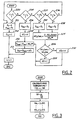
- step 200 a determination is made as to whether temperature (T) of catalyst 97 is below first threshold temperature T1. Calculation of first threshold temperature T1 is described later herein with particular reference to Figure 3.
- the desired mole ratio (Rdes) is set to zero in step 201 and the total quantity of reductant (Qtot) to be injected by control valve 134 is set to zero in step 202.
- Qtot total quantity of reductant
- Mole ratio (R) is the ratio of the number of moles of ammonia to the number of moles of nitrogen oxide in engine out exhaust gas.
- the moles of nitrogen oxide in engine out exhaust gas is calculated based on experimentally determined relationships between nitrogen oxide quantity and engine operating conditions known to those skilled in the art to be indicative of estimated engine out nitrogen oxide quantity (Nox est ) such as, for example, engine speed, manifold pressure (MAP), intake air temperature (AT), injection timing, injection quantity (FPW), and engine coolant temperature (ECT).
- Nox est estimated engine out nitrogen oxide quantity
- step 204 determines whether temperature (T) is below second threshold temperature T2.
- second threshold temperature T2 Calculation of second threshold temperature T2 is described later herein with particular reference to Figure 3.
- the desired mole ratio (Rdes) is set to second desired mole ratio (R2) in step 206.
- adjusted reductant quantity (DQ i ) for step i is set to zero in step 208.
- the base reductant quantity (Qbase) is determined from the product of the desired mole ratio (Rdes) and the estimated engine nitrogen oxide production (Nox est ) in step 210.
- step 212 total desired reductant quantity (Qtot) is determined from the sum of the base reductant quantity (Qbase) and the adjusted reductant quantity (DQ i ).
- the total desired reductant quantity (Qtot) is converted to a control signal sent to control valve 134 for delivering the reductant in proportional thereto.
- step 220 determines whether temperature (T) is below third threshold temperature T3. Calculation of third threshold temperature T3 is described later herein with particular reference to Figure 3.
- the desired mole ratio (Rdes) is set to third desired mole ratio (R3) in step 222.
- step 224 the value of the nitrogen oxide conversion efficiency (NOxConv i ) at step i is determined from sensor 140 and estimated engine out nitrogen oxide quantity (Nox est ).
- step 226 a determination is made as to whether the nitrogen oxide conversion efficiency at step i is greater than a desired NOx conversion efficiency.
- the desired NOx conversion efficiency (NOxDES) is determined as a fraction of estimated engine out nitrogen oxide quantity (Nox est ).
- the desired NOx conversion efficiency can be changed versus temperature (T). The optimum desired NOx conversion as a function of engine out NOx and catalyst temperature is determined from engine testing and stored as predetermined values.
- both the base reductant injection quantity and the desired NOx conversion control value are adjusted based on temperature to improve overall NOx conversion and ammonia slip.
- the desired NOx conversion efficiency can be calculated based on a base reductant injection quantity. More specifically, the desired NOx conversion efficiency can be calculated based on a predetermined percentage of base reductant injection quantity, where the predetermined percentage is mapped versus engine operating conditions..
- step 226 if the answer to step 226 is YES, then the adjusted reductant quantity (DQ i ) is set to a negative calibration amount (-r) in step 228. Otherwise, in step 230 the adjusted reductant quantity (DQ i ) is set to a positive calibration amount (r).
- step 236 determines whether temperature (T) is below fourth threshold temperature T4. Calculation of fourth threshold temperature T4 is described later herein with particular reference to Figure 3.
- the answer in step 236 is YES, the desired mole ratio (Rdes) is set to fourth desired mole ratio (R4) in step 238. Then, the routine continues to step 224 previous described herein.
- open loop reductant control is used to calculated the base reductant quantity (Qbase) from the product of the desired mole ratio (Rdes) and the estimated engine nitrogen oxide quantity (Nox est ). Also, desired mole ratio is adjusted based on catalyst temperature (T) to account for changes in catalyst efficiency.
- Adjustment is made to this open loop value in two temperature ranges to attain desired nitrogen oxide conversion efficiency based on measured nitrogen oxide from sensor 140 and estimated engine nitrogen oxide quantity. Further, desired nitrogen oxide conversion efficiency is determined based on both catalyst temperature and engine out NOx production.
- First based temperatures (T1B, ..., T4B) are determined based on predetermined calibration values in step 310.
- the space velocity (SV) of the flow exhaust gas flow entering catalyst 97 is calculated based on the mass flow rate (m), density (r), and catalyst Volume (V).
- adjustment values, (KA1, ..., KA4) are determined based on space velocity (SV) of the flow entering catalyst 97 and calibration functions (f1 ... f4).
- functions f1 ... f4 act to reduce temperatures as space velocity decreases and increase temperatures as space velocity increases.
- the invention may be used to advantage with both lean burning diesel and gasoline engines in which nitrogen oxide emissions are produced.
Landscapes
- Chemical & Material Sciences (AREA)
- Engineering & Computer Science (AREA)
- Chemical Kinetics & Catalysis (AREA)
- Health & Medical Sciences (AREA)
- Toxicology (AREA)
- Combustion & Propulsion (AREA)
- Mechanical Engineering (AREA)
- General Engineering & Computer Science (AREA)
- Exhaust Gas After Treatment (AREA)
Claims (10)
- Verfahren zur Steuerung einer Reduktionsmitteleinspritzung stromoberhalb eines mit einer Brennkraftmaschine (10) gekoppelten Katalysators (97), welches Verfahren die folgenden Schritte beinhaltet:Erstellen einer Reduktionsmittel-Einspritzmenge, ausgehend wenigstens von der in den Katalysator eintretenden Stickstoffoxydkonzentration;Bestimmen eines Stickstoffoxyd-Wandlungswirkungsgrades des Katalysators (97); undAnpassen der besagten Einspritzmenge zur Erzielung eines vorgegebenen Wertes des besagten Stickstoffoxyd-Wandlungswirkungsgrades.
- Verfahren nach Anspruch 1, worin besagter Schritt der Bestimmung des besagten Stickstoffoxyd-Wandlungswirkungsgrades außerdem folgende Schritte beinhaltet:Erstellen einer aus dem Katalysator austretenden Stickstoffoxydkonzentration mit einem stromunterhalb des Katalysators angeordneten Sensor;Erstellen einer in den Katalysator eintretenden Stickstoffoxydkonzentration anhand wenigstens einer Motorbetriebsbedingung unter Einsatz vorgegebener Kennlinienfelder; undErmitteln des besagten Stickstoffoxyd-Wandlungswirkungsgrades ausgehend von Eins minus die aus dem Katalysator austretende Stickstoffoxydkonzentration geteilt durch besagte in den Katalysator eintretende Stickstoffoxydkonzentration.
- Verfahren nach Anspruch 1 oder 2, worin besagter Anpassungsschritt außerdem folgende Schritte beinhaltet:Bestimmen eines Temperaturbereiches, in dem der Katalysator arbeitet; undAnpassen der besagten Einspritzmenge derart, daß besagter vorgegebener Wert für den Stickstoffoxyd-Wandlungswirkungsgrad erzielt wird, wenn besagter Temperaturbereich einer von mehreren vorgegebenen Temperaturbereichen ist, in welchen eine Steuerung des Wandlungswirkungsgrades erlaubt ist.
- Verfahren nach Anspruch 3, worin besagter Anpassungsschritt außerdem den Schritt der Senkung der besagten Einspritzmenge beinhaltet, wenn besagter Stickstoffoxyd-Wandlungswirkungsgrad größer als besagter vorgegebener Wert ist.
- Verfahren nach Anspruch 3, worin besagter Anpassungsschritt außerdem den Schritt der Erhöhung der besagten Einspritzmenge beinhaltet, wenn besagter Stickstoffoxyd-Wandlungswirkungsgrad kleiner als besagter vorgegebener Wert ist.
- Verfahren nach einem beliebigen der vorangehenden Ansprüche, worin besagter vorgegebener Wert ein Sollwert des NOx-Wandlungswirkungsgrades ist.
- Verfahren nach einem beliebigen der Ansprüche 1 bis 5, worin besagter vorgegebener Wert auf einer Motorbetriebsbedingung basiert.
- Verfahren nach einem beliebigen der vorangehenden Ansprüche, außerdem folgenden Schritt aufweisend:worin besagter vorgegebener Wert auf der in den Katalysator eintretenden Stickstoffoxydkonzentration basiert.Erstellen einer in den Katalysator eintretenden Stickstoffoxydkonzentration, ausgehend von Motorbetriebsbedingungen unter Verwendung vorgegebener Kennlinienfelder;
- Verfahren nach Anspruch 8, worin besagter vorgegebener Wert auch auf der Katalysatortemperatur basiert.
- Verfahren nach einem beliebigen der vorangehenden Ansprüche, worin besagtes Reduktionsmittel Ammoniak ist, und besagter vorgegebener Wert auf einem Prozentsatz der besagten Reduktionsmittel-Einspritzmenge basiert.
Applications Claiming Priority (2)
| Application Number | Priority Date | Filing Date | Title |
|---|---|---|---|
| US09/353,295 US6305160B1 (en) | 1999-07-12 | 1999-07-12 | Emission control system |
| US353295 | 1999-07-12 |
Publications (3)
| Publication Number | Publication Date |
|---|---|
| EP1069287A2 EP1069287A2 (de) | 2001-01-17 |
| EP1069287A3 EP1069287A3 (de) | 2002-06-19 |
| EP1069287B1 true EP1069287B1 (de) | 2004-04-07 |
Family
ID=23388519
Family Applications (1)
| Application Number | Title | Priority Date | Filing Date |
|---|---|---|---|
| EP00305910A Expired - Lifetime EP1069287B1 (de) | 1999-07-12 | 2000-07-12 | Abgasemissionsregeleinrichtung |
Country Status (3)
| Country | Link |
|---|---|
| US (1) | US6305160B1 (de) |
| EP (1) | EP1069287B1 (de) |
| DE (1) | DE60009609T2 (de) |
Cited By (1)
| Publication number | Priority date | Publication date | Assignee | Title |
|---|---|---|---|---|
| DE102011003670A1 (de) | 2011-02-04 | 2012-08-09 | Bosch Emission Systems Gmbh & Co. Kg | Betriebsverfahren |
Families Citing this family (29)
| Publication number | Priority date | Publication date | Assignee | Title |
|---|---|---|---|---|
| DE19921973A1 (de) * | 1999-05-12 | 2000-11-16 | Volkswagen Ag | Verfahren zur Entschwefelung von wenigstens einem in einem Abgaskanal einer Verbrennungskraftmaschine angeordneten NO¶x¶-Speicherkatalysator |
| DE19963901A1 (de) * | 1999-12-31 | 2001-07-12 | Bosch Gmbh Robert | Verfahren zum Betreiben eines Katalysators einer Brennkraftmaschine |
| DE60140104D1 (de) * | 2000-06-13 | 2009-11-19 | Ford Global Tech Inc | Verfahren zur Optimierung der Zugabe eines Reduktionmittels zu einem SCR-Katalysator einer Brennkraftmaschine |
| US6698188B2 (en) * | 2000-12-08 | 2004-03-02 | Toyota Jidosha Kabushiki Kaisha | Emission control apparatus of internal combustion engine |
| DE10100420A1 (de) * | 2001-01-08 | 2002-07-11 | Bosch Gmbh Robert | Verfahren und Vorrichtung zur Steuerung eines Abgasnachbehandlungssystems |
| US6993900B2 (en) | 2002-10-21 | 2006-02-07 | Ford Global Technologies, Llc | Exhaust gas aftertreatment systems |
| US6823663B2 (en) | 2002-11-21 | 2004-11-30 | Ford Global Technologies, Llc | Exhaust gas aftertreatment systems |
| US7093427B2 (en) | 2002-11-21 | 2006-08-22 | Ford Global Technologies, Llc | Exhaust gas aftertreatment systems |
| US6862879B2 (en) | 2002-11-21 | 2005-03-08 | Ford Global Technologies, Llc | Diesel aftertreatment system |
| US6834498B2 (en) | 2002-11-21 | 2004-12-28 | Ford Global Technologies, Llc | Diesel aftertreatment systems |
| US6981368B2 (en) * | 2002-11-21 | 2006-01-03 | Ford Global Technologies, Llc | Exhaust gas aftertreatment systems |
| US6928806B2 (en) * | 2002-11-21 | 2005-08-16 | Ford Global Technologies, Llc | Exhaust gas aftertreatment systems |
| US6895747B2 (en) | 2002-11-21 | 2005-05-24 | Ford Global Technologies, Llc | Diesel aftertreatment systems |
| US6892530B2 (en) | 2002-11-21 | 2005-05-17 | Ford Global Technologies, Llc | Exhaust gas aftertreatment systems |
| US6941746B2 (en) * | 2002-11-21 | 2005-09-13 | Combustion Components Associates, Inc. | Mobile diesel selective catalytic reduction systems and methods |
| US6871490B2 (en) * | 2002-12-19 | 2005-03-29 | Caterpillar Inc | Emissions control system for increasing selective catalytic reduction efficiency |
| US6925796B2 (en) * | 2003-11-19 | 2005-08-09 | Ford Global Technologies, Llc | Diagnosis of a urea SCR catalytic system |
| US7591106B2 (en) * | 2003-12-19 | 2009-09-22 | Marvin Lumber And Cedar Company | Flashing assembly |
| US7399729B2 (en) * | 2003-12-22 | 2008-07-15 | General Electric Company | Catalyst system for the reduction of NOx |
| US7784272B2 (en) * | 2004-08-31 | 2010-08-31 | Cummins Inc. | Control system for an engine aftertreatment system |
| DE102004046639A1 (de) * | 2004-09-25 | 2006-03-30 | Robert Bosch Gmbh | Verfahren zum Betreiben einer Brennkraftmaschine und Vorrichtung zur Durchführung des Verfahrens |
| DE102004046640B4 (de) * | 2004-09-25 | 2013-07-11 | Robert Bosch Gmbh | Verfahren zum Betreiben einer Brennkraftmaschine und Vorrichtung zur Durchführung des Verfahrens |
| US7426825B2 (en) * | 2006-07-25 | 2008-09-23 | Gm Global Technology Operations, Inc. | Method and apparatus for urea injection in an exhaust aftertreatment system |
| US20080202097A1 (en) * | 2007-02-28 | 2008-08-28 | Caterpillar Inc. | Engine exhaust treatment system |
| FR2922594A1 (fr) * | 2007-10-23 | 2009-04-24 | Peugeot Citroen Automobiles Sa | Procede de gestion d'injection d'uree dans un systeme a reduction catalytique selective |
| DE102008003260B4 (de) * | 2008-01-04 | 2009-10-01 | Eoil Automotive & Technologies Gmbh | Verfahren und Vorrichtung zur Dosierung der Zufuhr einer Harnstofflösung |
| US9518492B2 (en) * | 2008-04-23 | 2016-12-13 | Caterpillar Inc. | Exhaust system implementing in situ calibration |
| DE102008059773A1 (de) * | 2008-12-01 | 2010-06-02 | Volkswagen Ag | Verfahren zum Betreiben einer SCR-Katalysatoreinrichtung |
| US8413424B2 (en) * | 2009-01-23 | 2013-04-09 | Caterpillar Inc. | Stored reductant state for startup |
Family Cites Families (22)
| Publication number | Priority date | Publication date | Assignee | Title |
|---|---|---|---|---|
| JPS57159527A (en) * | 1981-03-26 | 1982-10-01 | Babcock Hitachi Kk | System for controlling reductant injecting amount in denitration apparatus |
| US4403473A (en) | 1981-06-22 | 1983-09-13 | Caterpillar Tractor Co. | Ammonia/fuel ratio control system for reducing nitrogen oxide emissions |
| GB2132112B (en) * | 1982-12-27 | 1986-08-20 | Gen Electric | Catalytic pollution control system for gas turbine exhaust |
| JPS6219229A (ja) | 1985-07-16 | 1987-01-28 | Babcock Hitachi Kk | アンモニアの注入量制御装置 |
| DE3604045C1 (de) * | 1986-02-08 | 1987-01-29 | Steag Ag | Verfahren zum Abscheiden von Stickstoffoxiden aus Rauchgasen |
| AT385915B (de) * | 1986-07-30 | 1988-06-10 | Jenbacher Werke Ag | Verfahren zur katalysator-steuerung und -regelung |
| CA1298957C (en) | 1987-01-27 | 1992-04-21 | Motonobu Kobayashi | Method for removal of nitrogen oxides from exhaust gas of diesel engine |
| US5201802A (en) * | 1991-02-04 | 1993-04-13 | Toyota Jidosha Kabushiki Kaisha | Exhaust gas purification system for an internal combustion engine |
| US5524432A (en) * | 1991-08-01 | 1996-06-11 | Air Products And Chemicals, Inc. | Catalytic reduction of nitrogen oxides in methane-fueled engine exhaust by controlled methane injections |
| DE4217552C1 (de) | 1992-05-27 | 1993-08-19 | Mercedes-Benz Aktiengesellschaft, 7000 Stuttgart, De | |
| US5233934A (en) | 1992-08-20 | 1993-08-10 | Wahlco Environmental Systems, Inc. | Control of NOx reduction in flue gas flows |
| DE4227741A1 (de) * | 1992-08-21 | 1994-02-24 | Bayerische Motoren Werke Ag | Verfahren zur Reduktion von in Abgasen enthaltenen Stickoxiden |
| US5367875A (en) * | 1992-12-07 | 1994-11-29 | Coltec Industries Inc | Automated catalytic reduction system |
| US5406790A (en) * | 1992-12-11 | 1995-04-18 | Toyota Jidosha Kabushiki Kaisha | Exhaust gas purification device for an engine |
| DE4334071C1 (de) | 1993-10-06 | 1995-02-09 | Siemens Ag | Verfahren zur Verminderung der Stickoxidkonzentration im Abgas einer Brennkraftmaschine oder einer Verbrennungsanlage |
| DE4436397B4 (de) * | 1994-10-12 | 2006-06-08 | Robert Bosch Gmbh | Einrichtung zum Nachbehandeln von Abgasen |
| JPH08284647A (ja) * | 1995-04-10 | 1996-10-29 | Nippon Soken Inc | 内燃機関の排気浄化装置に付設されるhc増量装置 |
| DE19536571C2 (de) * | 1995-09-29 | 1998-09-03 | Siemens Ag | Verfahren sowie Vorrichtung zur Dosierung der Eingabe eines Reduktionsmittels in den Abgas- oder Abluftstrom einer Verbrennungsanlage |
| US5709080A (en) * | 1996-03-15 | 1998-01-20 | Caterpillar Inc. | Leak detection method and apparatus for an exhaust purification system |
| DE19629163C1 (de) | 1996-07-19 | 1997-10-09 | Daimler Benz Ag | Verfahren und Vorrichtung zum stickoxidemissionsarmen Betrieb eines Verbrennungsmotors |
| US5809774A (en) * | 1996-11-19 | 1998-09-22 | Clean Diesel Technologies, Inc. | System for fueling and feeding chemicals to internal combustion engines for NOx reduction |
| DE19736384A1 (de) * | 1997-08-21 | 1999-02-25 | Man Nutzfahrzeuge Ag | Verfahren zur Dosierung eines Reduktionsmittels in stickoxidhaltiges Abgas einer Brennkraftmaschine |
-
1999
- 1999-07-12 US US09/353,295 patent/US6305160B1/en not_active Expired - Lifetime
-
2000
- 2000-07-12 EP EP00305910A patent/EP1069287B1/de not_active Expired - Lifetime
- 2000-07-12 DE DE60009609T patent/DE60009609T2/de not_active Expired - Lifetime
Cited By (1)
| Publication number | Priority date | Publication date | Assignee | Title |
|---|---|---|---|---|
| DE102011003670A1 (de) | 2011-02-04 | 2012-08-09 | Bosch Emission Systems Gmbh & Co. Kg | Betriebsverfahren |
Also Published As
| Publication number | Publication date |
|---|---|
| US6305160B1 (en) | 2001-10-23 |
| EP1069287A2 (de) | 2001-01-17 |
| EP1069287A3 (de) | 2002-06-19 |
| DE60009609D1 (de) | 2004-05-13 |
| DE60009609T2 (de) | 2005-04-14 |
Similar Documents
| Publication | Publication Date | Title |
|---|---|---|
| EP1069287B1 (de) | Abgasemissionsregeleinrichtung | |
| EP1069288B1 (de) | Abgasreinigungssystem mit einem Katalysator | |
| EP1164266B1 (de) | Verfahren zur Optimierung der Zugabe eines Reduktionmittels zu einem SCR-Katalysator einer Brennkraftmaschine | |
| US6182444B1 (en) | Emission control system | |
| US6253543B1 (en) | Lean catalyst and particulate filter control | |
| US7055313B2 (en) | Engine control system and method with lean catalyst and particulate filter | |
| US6427439B1 (en) | Method and system for NOx reduction | |
| US7134273B2 (en) | Exhaust emission control and diagnostics | |
| US6701707B1 (en) | Exhaust emission diagnostics | |
| US6983589B2 (en) | Diesel aftertreatment systems | |
| US7418816B2 (en) | Exhaust gas aftertreatment systems | |
| US6199375B1 (en) | Lean catalyst and particulate filter control system and method | |
| US6990854B2 (en) | Active lean NOx catalyst diagnostics | |
| US20070044456A1 (en) | Exhaust gas aftertreatment systems | |
| US20040244366A1 (en) | Exhaust gas purifying system and exhaust gas purifying method | |
| US20020184879A1 (en) | System & method for controlling the air / fuel ratio in an internal combustion engine | |
| US20070137181A1 (en) | Exhaust gas aftertreatment systems | |
| US20050252197A1 (en) | Diesel aftertreatment systems | |
| JPH1047048A (ja) | 内燃機関の排気浄化装置 | |
| US7475535B2 (en) | Diesel aftertreatment systems | |
| US6176228B1 (en) | Method for determining cylinder vapor concentration | |
| US20050066652A1 (en) | Diesel aftertreatment systems | |
| JP4039500B2 (ja) | 内燃機関の排気浄化装置 | |
| JP2005090352A (ja) | 内燃機関の制御装置及び内燃機関の制御方法 |
Legal Events
| Date | Code | Title | Description |
|---|---|---|---|
| PUAI | Public reference made under article 153(3) epc to a published international application that has entered the european phase |
Free format text: ORIGINAL CODE: 0009012 |
|
| AK | Designated contracting states |
Kind code of ref document: A2 Designated state(s): AT BE CH CY DE DK ES FI FR GB GR IE IT LI LU MC NL PT SE |
|
| AX | Request for extension of the european patent |
Free format text: AL;LT;LV;MK;RO;SI |
|
| PUAL | Search report despatched |
Free format text: ORIGINAL CODE: 0009013 |
|
| AK | Designated contracting states |
Kind code of ref document: A3 Designated state(s): AT BE CH CY DE DK ES FI FR GB GR IE IT LI LU MC NL PT SE |
|
| AX | Request for extension of the european patent |
Free format text: AL;LT;LV;MK;RO;SI |
|
| RIC1 | Information provided on ipc code assigned before grant |
Free format text: 7F 01N 3/08 A, 7F 01N 3/20 B, 7F 01N 11/00 B, 7F 01N 9/00 B |
|
| 17P | Request for examination filed |
Effective date: 20021030 |
|
| 17Q | First examination report despatched |
Effective date: 20030110 |
|
| AKX | Designation fees paid |
Designated state(s): DE FR GB |
|
| GRAP | Despatch of communication of intention to grant a patent |
Free format text: ORIGINAL CODE: EPIDOSNIGR1 |
|
| GRAS | Grant fee paid |
Free format text: ORIGINAL CODE: EPIDOSNIGR3 |
|
| RAP1 | Party data changed (applicant data changed or rights of an application transferred) |
Owner name: FORD GLOBAL TECHNOLOGIES, LLC |
|
| GRAA | (expected) grant |
Free format text: ORIGINAL CODE: 0009210 |
|
| AK | Designated contracting states |
Kind code of ref document: B1 Designated state(s): DE FR GB |
|
| PG25 | Lapsed in a contracting state [announced via postgrant information from national office to epo] |
Ref country code: FR Free format text: LAPSE BECAUSE OF FAILURE TO SUBMIT A TRANSLATION OF THE DESCRIPTION OR TO PAY THE FEE WITHIN THE PRESCRIBED TIME-LIMIT Effective date: 20040407 |
|
| REG | Reference to a national code |
Ref country code: GB Ref legal event code: FG4D |
|
| REF | Corresponds to: |
Ref document number: 60009609 Country of ref document: DE Date of ref document: 20040513 Kind code of ref document: P |
|
| REG | Reference to a national code |
Ref country code: IE Ref legal event code: FG4D |
|
| PGFP | Annual fee paid to national office [announced via postgrant information from national office to epo] |
Ref country code: FR Payment date: 20040702 Year of fee payment: 5 |
|
| PLBE | No opposition filed within time limit |
Free format text: ORIGINAL CODE: 0009261 |
|
| STAA | Information on the status of an ep patent application or granted ep patent |
Free format text: STATUS: NO OPPOSITION FILED WITHIN TIME LIMIT |
|
| EN | Fr: translation not filed | ||
| 26N | No opposition filed |
Effective date: 20050110 |
|
| REG | Reference to a national code |
Ref country code: IE Ref legal event code: MM4A |
|
| PGFP | Annual fee paid to national office [announced via postgrant information from national office to epo] |
Ref country code: GB Payment date: 20080616 Year of fee payment: 9 |
|
| GBPC | Gb: european patent ceased through non-payment of renewal fee |
Effective date: 20090712 |
|
| PG25 | Lapsed in a contracting state [announced via postgrant information from national office to epo] |
Ref country code: GB Free format text: LAPSE BECAUSE OF NON-PAYMENT OF DUE FEES Effective date: 20090712 |
|
| REG | Reference to a national code |
Ref country code: DE Ref legal event code: R082 Ref document number: 60009609 Country of ref document: DE Representative=s name: DOERFLER, THOMAS, DR.-ING., DE |
|
| PGFP | Annual fee paid to national office [announced via postgrant information from national office to epo] |
Ref country code: DE Payment date: 20170726 Year of fee payment: 18 |
|
| REG | Reference to a national code |
Ref country code: DE Ref legal event code: R119 Ref document number: 60009609 Country of ref document: DE |
|
| PG25 | Lapsed in a contracting state [announced via postgrant information from national office to epo] |
Ref country code: DE Free format text: LAPSE BECAUSE OF NON-PAYMENT OF DUE FEES Effective date: 20190201 |