EP1069253B1 - Structural systems and elements therefor - Google Patents
Structural systems and elements therefor Download PDFInfo
- Publication number
- EP1069253B1 EP1069253B1 EP20000305820 EP00305820A EP1069253B1 EP 1069253 B1 EP1069253 B1 EP 1069253B1 EP 20000305820 EP20000305820 EP 20000305820 EP 00305820 A EP00305820 A EP 00305820A EP 1069253 B1 EP1069253 B1 EP 1069253B1
- Authority
- EP
- European Patent Office
- Prior art keywords
- plank
- projections
- members
- connector
- stem
- Prior art date
- Legal status (The legal status is an assumption and is not a legal conclusion. Google has not performed a legal analysis and makes no representation as to the accuracy of the status listed.)
- Expired - Lifetime
Links
- 238000003491 array Methods 0.000 claims abstract description 7
- 238000005192 partition Methods 0.000 claims abstract description 7
- 238000010276 construction Methods 0.000 claims description 15
- 229920003023 plastic Polymers 0.000 claims description 15
- 239000004033 plastic Substances 0.000 claims description 15
- 238000001125 extrusion Methods 0.000 claims description 4
- 239000011800 void material Substances 0.000 claims description 4
- 238000003780 insertion Methods 0.000 claims description 2
- 230000037431 insertion Effects 0.000 claims description 2
- 239000000463 material Substances 0.000 description 9
- 239000002361 compost Substances 0.000 description 8
- 238000009434 installation Methods 0.000 description 4
- 239000003864 humus Substances 0.000 description 3
- 238000004519 manufacturing process Methods 0.000 description 3
- 239000000203 mixture Substances 0.000 description 3
- 239000004576 sand Substances 0.000 description 3
- 239000011521 glass Substances 0.000 description 2
- 238000003898 horticulture Methods 0.000 description 2
- 239000002184 metal Substances 0.000 description 2
- 229910052751 metal Inorganic materials 0.000 description 2
- 239000002689 soil Substances 0.000 description 2
- 241000282472 Canis lupus familiaris Species 0.000 description 1
- 241001465754 Metazoa Species 0.000 description 1
- 241000283984 Rodentia Species 0.000 description 1
- 210000000038 chest Anatomy 0.000 description 1
- 238000009264 composting Methods 0.000 description 1
- 230000006835 compression Effects 0.000 description 1
- 238000007906 compression Methods 0.000 description 1
- 239000000470 constituent Substances 0.000 description 1
- 238000000605 extraction Methods 0.000 description 1
- 150000002739 metals Chemical class 0.000 description 1
- 238000012986 modification Methods 0.000 description 1
- 230000004048 modification Effects 0.000 description 1
- 238000000465 moulding Methods 0.000 description 1
- 239000007787 solid Substances 0.000 description 1
- 241000894007 species Species 0.000 description 1
Images


Classifications
-
- E—FIXED CONSTRUCTIONS
- E04—BUILDING
- E04B—GENERAL BUILDING CONSTRUCTIONS; WALLS, e.g. PARTITIONS; ROOFS; FLOORS; CEILINGS; INSULATION OR OTHER PROTECTION OF BUILDINGS
- E04B1/00—Constructions in general; Structures which are not restricted either to walls, e.g. partitions, or floors or ceilings or roofs
- E04B1/38—Connections for building structures in general
- E04B1/58—Connections for building structures in general of bar-shaped building elements
- E04B1/5825—Connections for building structures in general of bar-shaped building elements with a closed cross-section
- E04B1/5831—Connections for building structures in general of bar-shaped building elements with a closed cross-section of substantially rectangular form
-
- A—HUMAN NECESSITIES
- A01—AGRICULTURE; FORESTRY; ANIMAL HUSBANDRY; HUNTING; TRAPPING; FISHING
- A01G—HORTICULTURE; CULTIVATION OF VEGETABLES, FLOWERS, RICE, FRUIT, VINES, HOPS OR SEAWEED; FORESTRY; WATERING
- A01G9/00—Cultivation in receptacles, forcing-frames or greenhouses; Edging for beds, lawn or the like
- A01G9/28—Raised beds; Planting beds; Edging elements for beds, lawn or the like, e.g. tiles
-
- C—CHEMISTRY; METALLURGY
- C05—FERTILISERS; MANUFACTURE THEREOF
- C05F—ORGANIC FERTILISERS NOT COVERED BY SUBCLASSES C05B, C05C, e.g. FERTILISERS FROM WASTE OR REFUSE
- C05F17/00—Preparation of fertilisers characterised by biological or biochemical treatment steps, e.g. composting or fermentation
- C05F17/90—Apparatus therefor
- C05F17/907—Small-scale devices without mechanical means for feeding or discharging material, e.g. garden compost bins
-
- Y—GENERAL TAGGING OF NEW TECHNOLOGICAL DEVELOPMENTS; GENERAL TAGGING OF CROSS-SECTIONAL TECHNOLOGIES SPANNING OVER SEVERAL SECTIONS OF THE IPC; TECHNICAL SUBJECTS COVERED BY FORMER USPC CROSS-REFERENCE ART COLLECTIONS [XRACs] AND DIGESTS
- Y02—TECHNOLOGIES OR APPLICATIONS FOR MITIGATION OR ADAPTATION AGAINST CLIMATE CHANGE
- Y02P—CLIMATE CHANGE MITIGATION TECHNOLOGIES IN THE PRODUCTION OR PROCESSING OF GOODS
- Y02P20/00—Technologies relating to chemical industry
- Y02P20/141—Feedstock
- Y02P20/145—Feedstock the feedstock being materials of biological origin
-
- Y—GENERAL TAGGING OF NEW TECHNOLOGICAL DEVELOPMENTS; GENERAL TAGGING OF CROSS-SECTIONAL TECHNOLOGIES SPANNING OVER SEVERAL SECTIONS OF THE IPC; TECHNICAL SUBJECTS COVERED BY FORMER USPC CROSS-REFERENCE ART COLLECTIONS [XRACs] AND DIGESTS
- Y02—TECHNOLOGIES OR APPLICATIONS FOR MITIGATION OR ADAPTATION AGAINST CLIMATE CHANGE
- Y02W—CLIMATE CHANGE MITIGATION TECHNOLOGIES RELATED TO WASTEWATER TREATMENT OR WASTE MANAGEMENT
- Y02W30/00—Technologies for solid waste management
- Y02W30/40—Bio-organic fraction processing; Production of fertilisers from the organic fraction of waste or refuse
Definitions
- This invention relates to structural systems and elements for use in the construction of such systems.
- the invention is particularly concerned with the provision of structures which may be advantageously for use in horticulture or the like making use of recycled materials, especially recycled plastics which can be used in the manufacture of the elements from which the structures are made, although it is not restricted to the use of such recycled materials and first use materials, such as suitable plastics, or metals may be used. In certain uses, such as horticulture, clear plastics may be of utility.
- FR A 2,596,821 describes and illustrates a movable structure comprised of a plurality of panels each comprised of a hollow body the interior of which is divided into channels by parallel partitions. The panels may be joined end to end or at right angles by connectors having projections which enter open ends of the channels. The structure is directed at the manufacture of furniture.
- US 3687512 (Alston) describes a drawer construction wherein the side walls of a drawer may be formed from wall members having longitudinally extending voids or cavities therein, which can be joined together end to end or at right angles by means of connector pieces which provide projections which extend into the open ends of the cavities, and may be joined by dowels passing through the walls of the wall members and the projections.
- FR A 2,596,821 basically is directed towards the construction of chests or other cabinets, and Apston US 3687512 is directed solely to the structure of pull-out drawers. No suggestion is given as to whether or how these constructions could be adopted to outdoor, horticultural use.
- a set of elements for use in the construction of a structural system comprises two or more plank members, each having at least one hollow or void in at least part thereof, and each open towards a respective end of the plank, and one or more connector members each comprising a body and a plurality of projections, each connector having at least one projection located to enter a respective hollow or void of each of at least two plank members to connect said plank members, characterised in that aligned apertures are provided adjacent each end of each plank member for alignment with apertures or notches in said projections of the connector members and in that rods are passed through said apertures or notches, to connect the plank members vertically.
- plank members each preferably comprise a plastics extrusion of uniform cross-section throughout the length of each plank member, and this may comprise a hollow rectangular section, subdivided by partitions or dividing walls into for example longitudinally extending compartments which form the hollows or voids which are open at each end of the plank member to receive projections of one or more connector members.
- the form of extrusion allows the plank member to be relatively light in weight, whilst the subdividing partitions or walls strengthen the plank member against compression exerted in the direction of the dividing walls.
- the connector member or members may each comprise a hollow or solid plastics body providing a stem, and formed with at least two arrays of projections for insertion into the open ends of the longitudinal compartments of two different plank members, so as to join the plank members together.
- Connector members may be provided in each of a range of forms for effecting different types of connection.
- the projections are preferably aligned on opposite sides of a square or rectangular stem.
- the projections are set at mutual right angles, on adjacent sides of a square or rectangular stem.
- the stem may be formed as a curved member with end faces formed which are at right angles to each other, and carrying the projections.
- the connector may provide a 'T' connection for three plank members.
- provision may be made for connections at angles other than right angles, such as 60 or 120 degrees.
- a modification of the connector comprising a stem with only one set of projections may be provided as a trim to 'finish' an exposed end of a plank member.
- Plank members may be connected vertically by means of rods which pass through apertures in the projections. These apertures may be in the form of closed holes, but for ease of manufacture, are preferably slots which open to one edge of the projections.
- the invention provides a structural system constructed from a set of elements according to the first aspect of the invention.
- Such horticultural structures may include for example a raised bed, or a sand pit wherein a single tier of plank members is secured together to form a low wall around a specified area, using both right angle (corner) connectors and straight-line connectors.
- the volume may then be filled with a soil/loam/humus/compost material or mixture to form a raised bed, or sand to form a sand pit.
- a structure of two or three superimposed tiers of plank members may be used as a pet run, to define an area in which a pet animal may be exercised, from rodents to small dogs.
- the height and extent of the enclosure will generally be related to the species involved.
- a simple high walled structure including for example up to ten or more tiers of plank members may be provided as a bin for collection and storage of garden or other rubbish, whilst a complex structure comprising a plurality of interconnected compartments of similar height to the bin may be designed as a compost installation.
- Such a compost installation may comprise for example three compartments, one or collection of current organic garden refuse, a second for compacting and maturing compost collected from a previous period, and a third for extraction of matured compost for use.
- a single tier structure may also be used as the basis for a cloche, in combination with a glass or clear plastics cover.
- Fig. 1 shows a plank member 10 which is a basic construction element of the invention.
- This comprises a moulding or extrusion of plastics, which may be clear or opaque and are preferably recycled plastics of any required length and of constant cross-section.
- the plank member 10 comprises an external shell 11 of rectangular cross-section, subdivided by partitions or webs 12 to form a plurality, e.g. five, of voids 13 which are open at each end of the plank member.
- Such plank members can be made to be of any desired dimensions and provided in any colour and be made from any suitable plastics material or blend of plastics materials to obtain required strength, rigidity or flexibility properties using recycled or first use plastics materials.
- Each of the partitions 12 and the end walls of the shell are formed with a hole 14. This is provided to enable fastening of the plank member 10 to a connector member as further described below.
- Figs. 2 and 4 illustrate two different connector configurations.
- Figs. 2 and 3 illustrate a first connector 20, which is for connecting plank members 10 in end-to-end straight line relationship.
- Connector 20 comprises a bracket 21 from which three spaced channel members 22, 23, 24 extend, each with two webs with open ended slots 25 towards each end. The members 22, 23, 24 enter into three of the five voids 13 in the plank member 10.
- Fig. 3 shows connector 20 with a plank member 10 with the projections 24 inserted into the voids 13 of the plank member.
- Slots 25 which are each open to one side of the projection, as shown in Fig. 3, cooperate with the holes 14 in the end of the respective plank member to form a passage through which a connector rod 26 or dowel, which may be of metal or a suitable strong plastics material, is passed.
- the rod 26 unites the connector 20 to the plank member 10, and is prevented from exiting the slots 25 in the connector by the holes 14 in the plank member.
- Connector rods 26 may extend to effect a vertical connection between several superposed tiers of plank members.
- Fig. 4 illustrates a variant from of connector 30, for use at corners, joining two plank members at right angles to each other.
- Connector 30 comprises a curved body 31 carrying three channel shaped projections 32, 33, 34 for entering into three of the five open end voids 13 of a respective plank member 10.
- the projections 32, 33, 34 each have two webs each with a slot 37 open to one side of the projections for receiving, in cooperation with holes 14 in the end of the plank member, respective connector rods 26, which, as noted in connection with Figs. 2 and 3, may extend vertically to connect a plurality of superposed tiers of plank members and are here shown as broken lines.
- Variant connectors which maybe used in special situations include a cruciform connector for joining four plank members 10 at mutual right angles, and this may comprise a cruciform body 41 formed with projections in the same manner as those described in connection with Figs. 2 and 3, and 4, including the provision of slots in the projections 46.
- a T-connector which has a T-shaped body with projections 55 in the same manner as the preceding embodiments of connector member, including the provision of slots in the projections.
- the basic connector member design may be modified for use as an end trim for any exposed (unconnected) plank member ends.
- This comprises a body with one set of projections 62 on one side for entry into the open ends of voids in the plank member 10.
- the projections each have a slot, this arrangement being the same as that described for the connector members.
- connector members 20, 30 are shown as being configured to connect a single tier of plank members, it is possible for them to be made of any required length, to join a plurality of superimposed tiers of plank members. This also applies to the end trim body.
- Figs. 5 and 6 and 7 and 8 each show a different possible horticultural structure made using elements such as those described above.
- a raised planting bed is constructed by forming a perimeter fence 70 from a single tier of plank elements 10, with corner connectors 30 and end-to-end connectors 20.
- the enclosure is then filled with a suitable plant growing medium such as humus, or a blend of humus and natural soil constituents, suitable for the crop or ornamental plants intended to be grown.
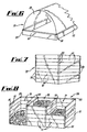
- a cloche or cold frame 71 wherein a base is formed by a single tier of plank members 10, with corner connectors 30 etc., with a cover 72 of a suitable glass or plastics transparent or translucent material.
- Fig. 7 shows a view of an enclosure 73 for use as a bin for collection of garden refuse. This comprises four walls (two not shown) each of several tiers of plank members 10, connected with corner connector members 30, which are each preferably of an extended variant with a single long stem with connectors for all of the tiers of plank members 10.
- Fig. 8- is a view of a horticultural structure comprising a composting installation 74, having three compartments 75, 76, 77 defined by walls each constructed of tiers of plank members 10 with corner connectors 30, and three way T-connections 50 where indicated.
- the front walls of the compartments are made so that the plank members 10 can be removed and replaced as required, so that, as shown by way of example, one compartment such as 77 can be partially walled up for collection of current organic refuse, a second compartment 76 can be walled up for maturing refuse collected during a previous period, into compost, and a third compartment 75 may be open at the front for the removal of fully matured compost for use.
Landscapes
- Engineering & Computer Science (AREA)
- Architecture (AREA)
- Life Sciences & Earth Sciences (AREA)
- Chemical & Material Sciences (AREA)
- Organic Chemistry (AREA)
- Biochemistry (AREA)
- Chemical Kinetics & Catalysis (AREA)
- General Chemical & Material Sciences (AREA)
- Microbiology (AREA)
- Molecular Biology (AREA)
- Health & Medical Sciences (AREA)
- Environmental Sciences (AREA)
- Physics & Mathematics (AREA)
- Biotechnology (AREA)
- Electromagnetism (AREA)
- Civil Engineering (AREA)
- Structural Engineering (AREA)
- Cultivation Receptacles Or Flower-Pots, Or Pots For Seedlings (AREA)
- Cultivation Of Plants (AREA)
- Superconductors And Manufacturing Methods Therefor (AREA)
- Joining Of Building Structures In Genera (AREA)
- Roof Covering Using Slabs Or Stiff Sheets (AREA)
- Burglar Alarm Systems (AREA)
Abstract
Description
- This invention relates to structural systems and elements for use in the construction of such systems.
- The invention is particularly concerned with the provision of structures which may be advantageously for use in horticulture or the like making use of recycled materials, especially recycled plastics which can be used in the manufacture of the elements from which the structures are made, although it is not restricted to the use of such recycled materials and first use materials, such as suitable plastics, or metals may be used. In certain uses, such as horticulture, clear plastics may be of utility.
- FR A 2,596,821 describes and illustrates a movable structure comprised of a plurality of panels each comprised of a hollow body the interior of which is divided into channels by parallel partitions. The panels may be joined end to end or at right angles by connectors having projections which enter open ends of the channels. The structure is directed at the manufacture of furniture. US 3687512 (Alston) describes a drawer construction wherein the side walls of a drawer may be formed from wall members having longitudinally extending voids or cavities therein, which can be joined together end to end or at right angles by means of connector pieces which provide projections which extend into the open ends of the cavities, and may be joined by dowels passing through the walls of the wall members and the projections.
- These structures are both limited to their use in construction of furniture, and are not suitable to -be adapted to construction of out-door structures such as compact enclosures or containment walls for raised beds. In particular whilst they may disclose, like Alston, a means for building up longer sides using joining elements.
- FR A 2,596,821 basically is directed towards the construction of chests or other cabinets, and Apston US 3687512 is directed solely to the structure of pull-out drawers. No suggestion is given as to whether or how these constructions could be adopted to outdoor, horticultural use.
- It is an object of the invention to provide elements for use in the construction of structural systems which can be assembled from a small range of simple components without skilled labour to provide a wide range of such structures.
- According to one aspect of the invention, a set of elements for use in the construction of a structural system, comprises two or more plank members, each having at least one hollow or void in at least part thereof, and each open towards a respective end of the plank, and one or more connector members each comprising a body and a plurality of projections, each connector having at least one projection located to enter a respective hollow or void of each of at least two plank members to connect said plank members, characterised in that aligned apertures are provided adjacent each end of each plank member for alignment with apertures or notches in said projections of the connector members and in that rods are passed through said apertures or notches, to connect the plank members vertically.
- The plank members each preferably comprise a plastics extrusion of uniform cross-section throughout the length of each plank member, and this may comprise a hollow rectangular section, subdivided by partitions or dividing walls into for example longitudinally extending compartments which form the hollows or voids which are open at each end of the plank member to receive projections of one or more connector members. The form of extrusion allows the plank member to be relatively light in weight, whilst the subdividing partitions or walls strengthen the plank member against compression exerted in the direction of the dividing walls.
- The connector member or members may each comprise a hollow or solid plastics body providing a stem, and formed with at least two arrays of projections for insertion into the open ends of the longitudinal compartments of two different plank members, so as to join the plank members together.
- Connector members may be provided in each of a range of forms for effecting different types of connection. For connection of two plank members in an end-to-end straight line arrangement, the projections are preferably aligned on opposite sides of a square or rectangular stem. For connection of two plank members at right angles, to form a corner, the projections are set at mutual right angles, on adjacent sides of a square or rectangular stem. On the other hand, the stem may be formed as a curved member with end faces formed which are at right angles to each other, and carrying the projections.
- In further embodiments of connector member, the connector may provide a 'T' connection for three plank members. In addition, provision may be made for connections at angles other than right angles, such as 60 or 120 degrees. A modification of the connector comprising a stem with only one set of projections may be provided as a trim to 'finish' an exposed end of a plank member.
- Plank members may be connected vertically by means of rods which pass through apertures in the projections. These apertures may be in the form of closed holes, but for ease of manufacture, are preferably slots which open to one edge of the projections.
- From another aspect, the invention provides a structural system constructed from a set of elements according to the first aspect of the invention. Such horticultural structures may include for example a raised bed, or a sand pit wherein a single tier of plank members is secured together to form a low wall around a specified area, using both right angle (corner) connectors and straight-line connectors. The volume may then be filled with a soil/loam/humus/compost material or mixture to form a raised bed, or sand to form a sand pit.
- A structure of two or three superimposed tiers of plank members may be used as a pet run, to define an area in which a pet animal may be exercised, from rodents to small dogs. The height and extent of the enclosure will generally be related to the species involved.
- A simple high walled structure including for example up to ten or more tiers of plank members may be provided as a bin for collection and storage of garden or other rubbish, whilst a complex structure comprising a plurality of interconnected compartments of similar height to the bin may be designed as a compost installation. Such a compost installation may comprise for example three compartments, one or collection of current organic garden refuse, a second for compacting and maturing compost collected from a previous period, and a third for extraction of matured compost for use.
- A single tier structure may also be used as the basis for a cloche, in combination with a glass or clear plastics cover.
- Preferred embodiments of structural systems and elements for use in constructions of such systems will now be described by way of example only, with reference to the accompanying drawings, wherein:-
- Figure 1
- is a perspective view of an end of a typical plank member forming part of a set of elements according to the invention;
- Figure 2
- is an elevation view of a connector member for joining two such plank members in an end-to-end straight line arrangement;
- Figure 3
- is a sectional view of part of the connector member of Figure 2 showing also an end of a plank member;
- Figure 4
- shows a perspective view of a connector member for joining two plank members at right angles, for example at a corner of a structure;
- Figure 5
- is a perspective view of a horticultural structure according to the invention in the form of a raised bed;
- Figure 6
- is a perspective view of a horticultural structure according to the invention in the form of a cloche;
- Figure 7
- is a perspective view of a horticultural structure according to the invention comprising a bin for collection of garden refuse; and
- Figure 8
- is a perspective view of a horticultural structure according to the invention comprising a compost installation for a garden.
- The drawings illustrate embodiments of horticultural constructions according to the invention and individual elements of a set of construction elements according to the invention, by way of example only.
- Fig. 1 shows a
plank member 10 which is a basic construction element of the invention. This comprises a moulding or extrusion of plastics, which may be clear or opaque and are preferably recycled plastics of any required length and of constant cross-section. As shown, theplank member 10 comprises anexternal shell 11 of rectangular cross-section, subdivided by partitions orwebs 12 to form a plurality, e.g. five, ofvoids 13 which are open at each end of the plank member. Such plank members can be made to be of any desired dimensions and provided in any colour and be made from any suitable plastics material or blend of plastics materials to obtain required strength, rigidity or flexibility properties using recycled or first use plastics materials. - Each of the
partitions 12 and the end walls of the shell are formed with ahole 14. This is provided to enable fastening of theplank member 10 to a connector member as further described below. - Figs. 2 and 4 illustrate two different connector configurations. Figs. 2 and 3 illustrate a
first connector 20, which is for connectingplank members 10 in end-to-end straight line relationship.Connector 20 comprises abracket 21 from which three spacedchannel members ended slots 25 towards each end. Themembers voids 13 in theplank member 10. Fig. 3 showsconnector 20 with aplank member 10 with theprojections 24 inserted into thevoids 13 of the plank member. -
Slots 25 which are each open to one side of the projection, as shown in Fig. 3, cooperate with theholes 14 in the end of the respective plank member to form a passage through which aconnector rod 26 or dowel, which may be of metal or a suitable strong plastics material, is passed. Therod 26 unites theconnector 20 to theplank member 10, and is prevented from exiting theslots 25 in the connector by theholes 14 in the plank member.Connector rods 26 may extend to effect a vertical connection between several superposed tiers of plank members. - Fig. 4 illustrates a variant from of
connector 30, for use at corners, joining two plank members at right angles to each other.Connector 30 comprises acurved body 31 carrying three channel shapedprojections respective plank member 10. In addition, theprojections slot 37 open to one side of the projections for receiving, in cooperation withholes 14 in the end of the plank member,respective connector rods 26, which, as noted in connection with Figs. 2 and 3, may extend vertically to connect a plurality of superposed tiers of plank members and are here shown as broken lines. - Variant connectors, not illustrated, which maybe used in special situations include a cruciform connector for joining four
plank members 10 at mutual right angles, and this may comprise a cruciform body 41 formed with projections in the same manner as those described in connection with Figs. 2 and 3, and 4, including the provision of slots in the projections 46. Another possibility is a T-connector, which has a T-shaped body with projections 55 in the same manner as the preceding embodiments of connector member, including the provision of slots in the projections. - In a further variant, the basic connector member design may be modified for use as an end trim for any exposed (unconnected) plank member ends. This comprises a body with one set of projections 62 on one side for entry into the open ends of voids in the
plank member 10. The projections each have a slot, this arrangement being the same as that described for the connector members. - Whilst the
connector members - Figs. 5 and 6 and 7 and 8 each show a different possible horticultural structure made using elements such as those described above.
- In Fig. 5, a raised planting bed is constructed by forming a
perimeter fence 70 from a single tier ofplank elements 10, withcorner connectors 30 and end-to-end connectors 20. The enclosure is then filled with a suitable plant growing medium such as humus, or a blend of humus and natural soil constituents, suitable for the crop or ornamental plants intended to be grown. - In Fig. 6 is shown a cloche or
cold frame 71 wherein a base is formed by a single tier ofplank members 10, withcorner connectors 30 etc., with acover 72 of a suitable glass or plastics transparent or translucent material. - Fig. 7 shows a view of an
enclosure 73 for use as a bin for collection of garden refuse. This comprises four walls (two not shown) each of several tiers ofplank members 10, connected withcorner connector members 30, which are each preferably of an extended variant with a single long stem with connectors for all of the tiers ofplank members 10. - Finally, Fig. 8- is a view of a horticultural structure comprising a
composting installation 74, having threecompartments plank members 10 withcorner connectors 30, and three way T-connections 50 where indicated. The front walls of the compartments are made so that theplank members 10 can be removed and replaced as required, so that, as shown by way of example, one compartment such as 77 can be partially walled up for collection of current organic refuse, asecond compartment 76 can be walled up for maturing refuse collected during a previous period, into compost, and a third compartment 75 may be open at the front for the removal of fully matured compost for use. - Variations to the design and configuration of the construction elements may be made within the scope of the invention, particularly with regard to the number of voids and projections used, and the shapes of various components. Also, the above instances of horticultural constructions are given as non-limiting examples, and the configuration and purpose of these may be varied within the scope of the invention.
Claims (10)
- A set of elements for use in the construction of a structural system, comprising two or more plank members (10), each having at least one hollow or void (13) in at least part thereof, and each open towards a respective end of the plank, and one or more connector members (20) each comprising a body (21) and a plurality of projections (22, 23, 24); each connector (20) having at least one of the projections (22, 23 or 24) located to enter a respective hollow or void (13) of each of the at least two plank members (10) to connect said plank members, characterised in that aligned apertures (14) are provided adjacent each end of each of the plank members (10) for alignment with apertures or notches (25) in said projections (22, 23, 24) of the connector members (20) and in that rods (26) are passed through said apertures (14) and apertures or notches (25) to connect the plank members (10) vertically.
- A set of elements according to claim 1, wherein each plank member (10) comprises a plastics extrusion of uniform cross-section throughout its length, and comprise a hollow rectangular cross-section subdivided by partitions or dividing walls (12) into longitudinally extending compartments (13), which form said hollows or voids and are open at each end of the plank member to receive said projections (22, 23, 24) of one or more of the connector members 20.
- A set of elements according to claim 2 wherein each connector member (20) comprises a plastics body providing a stem (21), and at least two arrays of projections (22, 23, 24) provided on the stem (21), for insertion into the open ends of the longitudinal extending compartments (13) of two different plank members (10), so as to joint the plank members together.
- A set of elements according to claim 3, wherein at least one connector member (20) is provided wherein the arrays of projections (22, 23, 24) are aligned on opposite sides of the stem (21).
- A set of elements according to claim 3, wherein at least one connector member (20) is provided, wherein the arrays of projections (32, 33, 34) are set at mutual right angles on the stem (31).
- A set of elements according to either of claims 4 or 5, wherein the stem (21), is square or rectangular in cross-section.
- A set of elements according to claim 5, wherein the stem (31) is formed as a curved member with end faces which are at right angles to each other, and carry the projections (32, 33, 34).
- A set of elements according to claim 3, wherein at least one connector member is provided with three arrays of projections on said stem, arranged at mutual right angles.
- A set of elements according to claim 3, including a modified connector member comprising a stem and a single array of projections, to act as a trim to close an exposed end of a plank member.
- A structure constructed from a set of elements according to any preceding claim.
Applications Claiming Priority (2)
| Application Number | Priority Date | Filing Date | Title |
|---|---|---|---|
| GB9916625 | 1999-07-16 | ||
| GB9916625A GB2355470B (en) | 1999-07-16 | 1999-07-16 | Structural systems and elements therefor |
Publications (3)
| Publication Number | Publication Date |
|---|---|
| EP1069253A2 EP1069253A2 (en) | 2001-01-17 |
| EP1069253A3 EP1069253A3 (en) | 2002-01-30 |
| EP1069253B1 true EP1069253B1 (en) | 2005-06-01 |
Family
ID=10857302
Family Applications (1)
| Application Number | Title | Priority Date | Filing Date |
|---|---|---|---|
| EP20000305820 Expired - Lifetime EP1069253B1 (en) | 1999-07-16 | 2000-07-10 | Structural systems and elements therefor |
Country Status (7)
| Country | Link |
|---|---|
| US (1) | US6532707B1 (en) |
| EP (1) | EP1069253B1 (en) |
| AT (1) | ATE296926T1 (en) |
| DE (1) | DE60020455T2 (en) |
| ES (1) | ES2243204T3 (en) |
| GB (1) | GB2355470B (en) |
| PT (1) | PT1069253E (en) |
Families Citing this family (12)
| Publication number | Priority date | Publication date | Assignee | Title |
|---|---|---|---|---|
| GB0303978D0 (en) * | 2003-02-20 | 2003-03-26 | Acer Prod Ltd | Building panel |
| GB0606640D0 (en) * | 2006-04-01 | 2006-05-10 | Armillatox Ltd | Horticultural apparatus |
| BRPI0807970B1 (en) * | 2007-01-24 | 2018-06-12 | Reynolds Consumer Products, Inc. | FIXING DEVICE FOR PORTABLE POROUS FLOOR SYSTEM |
| WO2008091879A1 (en) * | 2007-01-24 | 2008-07-31 | Reynolds Consumer Products, Inc. | Portable porous pavement system and method for assembling such a pavement system |
| US7966766B2 (en) * | 2009-03-24 | 2011-06-28 | Vogler Michael R | Raised garden bed kit |
| AU2015100963B4 (en) * | 2011-09-29 | 2016-03-03 | Daniel Gobbo | A Garden Edging System |
| US9725873B2 (en) * | 2013-11-12 | 2017-08-08 | Contech Engineered Solutions LLC | Secondary containment system |
| US9382038B2 (en) | 2014-04-04 | 2016-07-05 | Tyco Electronics Corporation | Modular enclosure |
| US9392708B2 (en) * | 2014-04-04 | 2016-07-12 | Tyco Electronics Corporation | Modular enclosure |
| US10548232B2 (en) | 2017-10-02 | 2020-01-28 | Te Connectivity Corporation | Modular enclosure and an assembly for constructing a modular enclosure |
| DE102020120556B4 (en) | 2020-08-04 | 2024-11-28 | Elena Welt | PROFILE AND SYSTEM FOR EDGING AREAS |
| EP4627909A1 (en) * | 2024-04-04 | 2025-10-08 | Lorenz Kunststofftechnik GmbH | Variable capacity lift fence boundary |
Family Cites Families (41)
| Publication number | Priority date | Publication date | Assignee | Title |
|---|---|---|---|---|
| US1365753A (en) * | 1919-12-11 | 1921-01-18 | George W Vought | Mold for making tiles |
| US1416919A (en) * | 1921-09-12 | 1922-05-23 | John A Wickson | Building block |
| US1477867A (en) * | 1922-02-20 | 1923-12-18 | David W Dodson | Building wall |
| US1495439A (en) * | 1923-06-14 | 1924-05-27 | George D Reagan | Tile brick or building tile |
| US1716626A (en) * | 1926-08-11 | 1929-06-11 | Vol James C De | Metal tile |
| US1835524A (en) * | 1928-11-17 | 1931-12-08 | Johns Manville | Electrical cell and compartment structure |
| GB908260A (en) * | 1958-07-31 | 1962-10-17 | Gloucester Stone Company Ltd | Improvements in and relating to joints in concrete structural members and structuresincorporating such joints |
| US3148230A (en) * | 1961-12-05 | 1964-09-08 | North American Refractories | Refractory structure |
| FR1435227A (en) * | 1965-03-16 | 1966-04-15 | Assembly device and parts for the execution of panels, partitions and similar constructions | |
| GB1189907A (en) * | 1967-10-16 | 1970-04-29 | Leslie William Llewelly Alston | Improvements in or relating to Drawers for Furniture |
| US3511004A (en) * | 1968-01-12 | 1970-05-12 | Republic Steel Corp | Corrugated sheet metal structure |
| US3879914A (en) * | 1969-09-23 | 1975-04-29 | Hans Haller | Method of making a platform structure |
| AT307656B (en) * | 1970-12-14 | 1973-06-12 | Duepree Hans Werner | System component |
| US4145854A (en) * | 1975-01-16 | 1979-03-27 | Plan-Tek A/S | Load-carrying building structure particularly ceilings, floor and the like |
| GB1507498A (en) * | 1975-05-30 | 1978-04-12 | Swish Prod | Structural elements |
| US4162114A (en) * | 1977-04-26 | 1979-07-24 | L. B. (Plastics) Limited | Drawers and drawer components |
| US4147001A (en) * | 1977-11-07 | 1979-04-03 | Oliver Wayne H | Connector for wall panel structure |
| GB1603980A (en) * | 1978-05-13 | 1981-12-02 | Lb Plastics Ltd | Structural components |
| DE3035043A1 (en) * | 1980-09-17 | 1982-04-29 | Artur Dr.H.C. 7244 Waldachtal Fischer | FASTENING ELEMENT FOR HOLLOW CHAMBER PANELS |
| US4388786A (en) * | 1981-01-30 | 1983-06-21 | Kurt Gassler | Construction means for use in the assembly of wall and/or roof structures |
| US4382046A (en) * | 1981-09-22 | 1983-05-03 | Ceramic Cooling Tower Company | Water cooling tower with layers of multi-cell tiles and spacers |
| GB2142058A (en) * | 1983-06-21 | 1985-01-09 | Robert Jennings Hepworth | Panel securing device |
| FR2576624B1 (en) * | 1985-01-30 | 1989-06-30 | Melco | PREFABRICATED PROTECTIVE SHELTER WITH COMPOSITE STRUCTURE. |
| US4683674A (en) * | 1985-11-15 | 1987-08-04 | Barclay Horticulture Mfg. Ltd. | Compost bin |
| FR2596821A1 (en) * | 1986-04-07 | 1987-10-09 | Gigot Philippe | Self-supporting structure which can be used especially as a piece of furniture and is composed of assembled plastic plates |
| US4778309A (en) * | 1987-03-30 | 1988-10-18 | Presto Products, Incorporated | Stackable grid material for soil confinement |
| US4915540A (en) * | 1989-06-05 | 1990-04-10 | Jack Kennedy Metal Products And Buildings, Inc. | Contractible mine stopping and contractible block member for use therein |
| US5155961A (en) * | 1989-08-14 | 1992-10-20 | Amsted Industries Incorporated | Lightweight cooling tower with cruciform columns |
| CA2070079C (en) * | 1992-05-29 | 1997-06-10 | Vittorio De Zen | Thermoplastic structural system and components therefor and method of making same |
| US5511345A (en) * | 1993-07-13 | 1996-04-30 | Vantage Products Corporation | Unitary molded plastic structural member, lid form and lawn crypt constructed from same |
| US5412918A (en) * | 1993-10-29 | 1995-05-09 | Exhibit Group, Inc. | Attachment system for modular panels |
| US5634300A (en) * | 1994-03-10 | 1997-06-03 | Plascore Inc. | Wall system employing grooved posts, connector blocks and T-bolt receiving battens |
| EP0754104B1 (en) * | 1994-03-31 | 1998-12-09 | British Steel Plc | Improvements in and relating to double skin composite structures |
| US5471806A (en) * | 1994-09-29 | 1995-12-05 | Rokhlin; Zinoviy A. | Construction panel with plurality of cells |
| US5647181A (en) * | 1994-10-11 | 1997-07-15 | Hunts; Larry David | Construction system and method for connecting rigid sheet-like panels together into doll houses, play houses, utility sheds and other structures |
| US5493839A (en) * | 1995-02-21 | 1996-02-27 | Sax; Hilary H. | Structural building panel and panel system |
| EP0792979A1 (en) * | 1996-02-27 | 1997-09-03 | Ehlebracht AG | Modular cladding system |
| US6250022B1 (en) * | 1998-08-10 | 2001-06-26 | Keter Plastic Ltd. | Extendible shed |
| US6176053B1 (en) * | 1998-08-27 | 2001-01-23 | Roger C. A. St. Germain | Wall track assembly and method for installing the same |
| ITMI990004A1 (en) * | 1999-01-04 | 2000-07-04 | Giancarlo Locatelli | UPHOLSTERY WITH INTEGRATED EDUCATIONAL ASSISTANCE |
| US6099411A (en) * | 1999-09-21 | 2000-08-08 | Western Mill Fabricators, Inc. | Multi-layer and multi-chamber play structure |
-
1999
- 1999-07-16 GB GB9916625A patent/GB2355470B/en not_active Expired - Fee Related
-
2000
- 2000-07-10 AT AT00305820T patent/ATE296926T1/en not_active IP Right Cessation
- 2000-07-10 PT PT00305820T patent/PT1069253E/en unknown
- 2000-07-10 ES ES00305820T patent/ES2243204T3/en not_active Expired - Lifetime
- 2000-07-10 EP EP20000305820 patent/EP1069253B1/en not_active Expired - Lifetime
- 2000-07-10 DE DE2000620455 patent/DE60020455T2/en not_active Expired - Fee Related
- 2000-07-14 US US09/616,935 patent/US6532707B1/en not_active Expired - Fee Related
Also Published As
| Publication number | Publication date |
|---|---|
| EP1069253A3 (en) | 2002-01-30 |
| ATE296926T1 (en) | 2005-06-15 |
| GB2355470A (en) | 2001-04-25 |
| GB9916625D0 (en) | 1999-09-15 |
| PT1069253E (en) | 2005-09-30 |
| ES2243204T3 (en) | 2005-12-01 |
| EP1069253A2 (en) | 2001-01-17 |
| GB2355470B (en) | 2003-03-12 |
| DE60020455D1 (en) | 2005-07-07 |
| DE60020455T2 (en) | 2006-04-27 |
| US6532707B1 (en) | 2003-03-18 |
Similar Documents
| Publication | Publication Date | Title |
|---|---|---|
| EP1069253B1 (en) | Structural systems and elements therefor | |
| CA2118008C (en) | Shelves, shelving or partitioning system | |
| US7581357B2 (en) | Plastic expandable utility shed | |
| RU2769877C1 (en) | Expandable modular frame for pet cage formation | |
| US20070157530A1 (en) | Plastic utility shed roof system | |
| US11116146B2 (en) | Cultivation assembly | |
| EP3657984A1 (en) | Shelf module unit having side wall perforated plates and connecting structure | |
| KR20160022968A (en) | Variable modular kitchen garden | |
| WO1997028682A1 (en) | Three-dimensional modular cultivation container | |
| EP1548368A1 (en) | Set of drawer kitchen hoods | |
| EP0095694B1 (en) | Construction element for building houses, windows, trays and the like | |
| EP0641479B1 (en) | Combination system for holding boxed compact disks | |
| EP2294266B1 (en) | Wall, ceiling, or floor element as well as structure and assembly comprising such elements | |
| EP3228184B1 (en) | Modular system for building a plantable wall | |
| RU2181537C1 (en) | Container for growing plants and planting into ground | |
| DE3131017C2 (en) | Cage battery | |
| GB2217565A (en) | Plant protection | |
| EP4725308A1 (en) | A colonisation device | |
| DE3734074C2 (en) | ||
| DE9214913U1 (en) | Raised bed and terrace system | |
| DE202024107038U1 (en) | Modular protection of at least one object against weather influences, in particular for the protection of plants in outdoor areas as well as shaped stone and cover for modular protection | |
| DE102022200028A1 (en) | Domestic refrigeration appliance with a configurable housing and method for assembling a domestic refrigeration appliance | |
| AT413780B (en) | PLANTING SYSTEM | |
| EP3769608A1 (en) | Cultivation assembly | |
| DE2513067A1 (en) | Parallelepiped base-framed room structure element - with attachable wall components of uniform size matching shorter frame sides |
Legal Events
| Date | Code | Title | Description |
|---|---|---|---|
| PUAI | Public reference made under article 153(3) epc to a published international application that has entered the european phase |
Free format text: ORIGINAL CODE: 0009012 |
|
| AK | Designated contracting states |
Kind code of ref document: A2 Designated state(s): AT BE CH CY DE DK ES FI FR GB GR IE IT LI LU MC NL PT SE |
|
| AX | Request for extension of the european patent |
Free format text: AL;LT;LV;MK;RO;SI |
|
| PUAL | Search report despatched |
Free format text: ORIGINAL CODE: 0009013 |
|
| AK | Designated contracting states |
Kind code of ref document: A3 Designated state(s): AT BE CH CY DE DK ES FI FR GB GR IE IT LI LU MC NL PT SE |
|
| AX | Request for extension of the european patent |
Free format text: AL;LT;LV;MK;RO;SI |
|
| 17P | Request for examination filed |
Effective date: 20020729 |
|
| AKX | Designation fees paid |
Free format text: AT BE CH CY DE DK ES FI FR GB GR IE IT LI LU MC NL PT SE |
|
| 17Q | First examination report despatched |
Effective date: 20040802 |
|
| GRAP | Despatch of communication of intention to grant a patent |
Free format text: ORIGINAL CODE: EPIDOSNIGR1 |
|
| GRAS | Grant fee paid |
Free format text: ORIGINAL CODE: EPIDOSNIGR3 |
|
| GRAA | (expected) grant |
Free format text: ORIGINAL CODE: 0009210 |
|
| AK | Designated contracting states |
Kind code of ref document: B1 Designated state(s): AT BE CH CY DE DK ES FI FR GB GR IE IT LI LU MC NL PT SE |
|
| PG25 | Lapsed in a contracting state [announced via postgrant information from national office to epo] |
Ref country code: FI Free format text: LAPSE BECAUSE OF FAILURE TO SUBMIT A TRANSLATION OF THE DESCRIPTION OR TO PAY THE FEE WITHIN THE PRESCRIBED TIME-LIMIT Effective date: 20050601 |
|
| REG | Reference to a national code |
Ref country code: GB Ref legal event code: FG4D |
|
| REG | Reference to a national code |
Ref country code: CH Ref legal event code: EP |
|
| REG | Reference to a national code |
Ref country code: IE Ref legal event code: FG4D |
|
| REF | Corresponds to: |
Ref document number: 60020455 Country of ref document: DE Date of ref document: 20050707 Kind code of ref document: P |
|
| PG25 | Lapsed in a contracting state [announced via postgrant information from national office to epo] |
Ref country code: DK Free format text: LAPSE BECAUSE OF FAILURE TO SUBMIT A TRANSLATION OF THE DESCRIPTION OR TO PAY THE FEE WITHIN THE PRESCRIBED TIME-LIMIT Effective date: 20050901 Ref country code: SE Free format text: LAPSE BECAUSE OF FAILURE TO SUBMIT A TRANSLATION OF THE DESCRIPTION OR TO PAY THE FEE WITHIN THE PRESCRIBED TIME-LIMIT Effective date: 20050901 |
|
| REG | Reference to a national code |
Ref country code: GR Ref legal event code: EP Ref document number: 20050402623 Country of ref document: GR |
|
| REG | Reference to a national code |
Ref country code: PT Ref legal event code: SC4A Effective date: 20050801 Ref country code: CH Ref legal event code: NV Representative=s name: FREI PATENTANWALTSBUERO |
|
| REG | Reference to a national code |
Ref country code: ES Ref legal event code: FG2A Ref document number: 2243204 Country of ref document: ES Kind code of ref document: T3 |
|
| ET | Fr: translation filed | ||
| PLBE | No opposition filed within time limit |
Free format text: ORIGINAL CODE: 0009261 |
|
| STAA | Information on the status of an ep patent application or granted ep patent |
Free format text: STATUS: NO OPPOSITION FILED WITHIN TIME LIMIT |
|
| 26N | No opposition filed |
Effective date: 20060302 |
|
| PGFP | Annual fee paid to national office [announced via postgrant information from national office to epo] |
Ref country code: CY Payment date: 20060613 Year of fee payment: 7 |
|
| PGFP | Annual fee paid to national office [announced via postgrant information from national office to epo] |
Ref country code: MC Payment date: 20060616 Year of fee payment: 7 Ref country code: PT Payment date: 20060616 Year of fee payment: 7 |
|
| PGFP | Annual fee paid to national office [announced via postgrant information from national office to epo] |
Ref country code: LU Payment date: 20060620 Year of fee payment: 7 |
|
| PGFP | Annual fee paid to national office [announced via postgrant information from national office to epo] |
Ref country code: AT Payment date: 20060703 Year of fee payment: 7 |
|
| PGFP | Annual fee paid to national office [announced via postgrant information from national office to epo] |
Ref country code: GR Payment date: 20060731 Year of fee payment: 7 |
|
| PGFP | Annual fee paid to national office [announced via postgrant information from national office to epo] |
Ref country code: IE Payment date: 20070716 Year of fee payment: 8 |
|
| PGFP | Annual fee paid to national office [announced via postgrant information from national office to epo] |
Ref country code: DE Payment date: 20070809 Year of fee payment: 8 |
|
| PGFP | Annual fee paid to national office [announced via postgrant information from national office to epo] |
Ref country code: ES Payment date: 20070830 Year of fee payment: 8 |
|
| PGFP | Annual fee paid to national office [announced via postgrant information from national office to epo] |
Ref country code: CH Payment date: 20070810 Year of fee payment: 8 |
|
| PGFP | Annual fee paid to national office [announced via postgrant information from national office to epo] |
Ref country code: GB Payment date: 20070801 Year of fee payment: 8 |
|
| REG | Reference to a national code |
Ref country code: PT Ref legal event code: MM4A Free format text: LAPSE DUE TO NON-PAYMENT OF FEES Effective date: 20080110 |
|
| PGFP | Annual fee paid to national office [announced via postgrant information from national office to epo] |
Ref country code: BE Payment date: 20070817 Year of fee payment: 8 Ref country code: IT Payment date: 20070731 Year of fee payment: 8 Ref country code: NL Payment date: 20070731 Year of fee payment: 8 |
|
| PG25 | Lapsed in a contracting state [announced via postgrant information from national office to epo] |
Ref country code: MC Free format text: LAPSE BECAUSE OF NON-PAYMENT OF DUE FEES Effective date: 20070731 |
|
| PGFP | Annual fee paid to national office [announced via postgrant information from national office to epo] |
Ref country code: FR Payment date: 20070731 Year of fee payment: 8 |
|
| PG25 | Lapsed in a contracting state [announced via postgrant information from national office to epo] |
Ref country code: PT Free format text: LAPSE BECAUSE OF NON-PAYMENT OF DUE FEES Effective date: 20080110 |
|
| PG25 | Lapsed in a contracting state [announced via postgrant information from national office to epo] |
Ref country code: AT Free format text: LAPSE BECAUSE OF NON-PAYMENT OF DUE FEES Effective date: 20070710 Ref country code: CY Free format text: LAPSE BECAUSE OF NON-PAYMENT OF DUE FEES Effective date: 20070710 |
|
| PG25 | Lapsed in a contracting state [announced via postgrant information from national office to epo] |
Ref country code: GR Free format text: LAPSE BECAUSE OF NON-PAYMENT OF DUE FEES Effective date: 20080206 |
|
| REG | Reference to a national code |
Ref country code: CH Ref legal event code: PL |
|
| GBPC | Gb: european patent ceased through non-payment of renewal fee |
Effective date: 20080710 |
|
| NLV4 | Nl: lapsed or anulled due to non-payment of the annual fee |
Effective date: 20090201 |
|
| REG | Reference to a national code |
Ref country code: IE Ref legal event code: MM4A |
|
| PG25 | Lapsed in a contracting state [announced via postgrant information from national office to epo] |
Ref country code: DE Free format text: LAPSE BECAUSE OF NON-PAYMENT OF DUE FEES Effective date: 20090203 |
|
| REG | Reference to a national code |
Ref country code: FR Ref legal event code: ST Effective date: 20090331 |
|
| PG25 | Lapsed in a contracting state [announced via postgrant information from national office to epo] |
Ref country code: NL Free format text: LAPSE BECAUSE OF NON-PAYMENT OF DUE FEES Effective date: 20090201 |
|
| PG25 | Lapsed in a contracting state [announced via postgrant information from national office to epo] |
Ref country code: GB Free format text: LAPSE BECAUSE OF NON-PAYMENT OF DUE FEES Effective date: 20080710 Ref country code: CH Free format text: LAPSE BECAUSE OF NON-PAYMENT OF DUE FEES Effective date: 20080731 Ref country code: LI Free format text: LAPSE BECAUSE OF NON-PAYMENT OF DUE FEES Effective date: 20080731 |
|
| PG25 | Lapsed in a contracting state [announced via postgrant information from national office to epo] |
Ref country code: IE Free format text: LAPSE BECAUSE OF NON-PAYMENT OF DUE FEES Effective date: 20080710 |
|
| PG25 | Lapsed in a contracting state [announced via postgrant information from national office to epo] |
Ref country code: LU Free format text: LAPSE BECAUSE OF NON-PAYMENT OF DUE FEES Effective date: 20070710 Ref country code: IT Free format text: LAPSE BECAUSE OF NON-PAYMENT OF DUE FEES Effective date: 20080710 Ref country code: FR Free format text: LAPSE BECAUSE OF NON-PAYMENT OF DUE FEES Effective date: 20080731 |
|
| REG | Reference to a national code |
Ref country code: ES Ref legal event code: FD2A Effective date: 20080711 |
|
| PG25 | Lapsed in a contracting state [announced via postgrant information from national office to epo] |
Ref country code: ES Free format text: LAPSE BECAUSE OF NON-PAYMENT OF DUE FEES Effective date: 20080711 |
|
| PG25 | Lapsed in a contracting state [announced via postgrant information from national office to epo] |
Ref country code: BE Free format text: LAPSE BECAUSE OF NON-PAYMENT OF DUE FEES Effective date: 20080731 |