EP1069244B1 - Method for monitoring a downhole vibrator - Google Patents
Method for monitoring a downhole vibrator Download PDFInfo
- Publication number
- EP1069244B1 EP1069244B1 EP00114397A EP00114397A EP1069244B1 EP 1069244 B1 EP1069244 B1 EP 1069244B1 EP 00114397 A EP00114397 A EP 00114397A EP 00114397 A EP00114397 A EP 00114397A EP 1069244 B1 EP1069244 B1 EP 1069244B1
- Authority
- EP
- European Patent Office
- Prior art keywords
- vibrator
- rotation
- deep
- leader
- pipe
- Prior art date
- Legal status (The legal status is an assumption and is not a legal conclusion. Google has not performed a legal analysis and makes no representation as to the accuracy of the status listed.)
- Expired - Lifetime
Links
- 238000000034 method Methods 0.000 title claims abstract description 11
- 238000012544 monitoring process Methods 0.000 title description 2
- 230000008878 coupling Effects 0.000 claims abstract description 5
- 238000010168 coupling process Methods 0.000 claims abstract description 5
- 238000005859 coupling reaction Methods 0.000 claims abstract description 5
- 229910000831 Steel Inorganic materials 0.000 claims abstract description 3
- 239000010959 steel Substances 0.000 claims abstract description 3
- 239000002689 soil Substances 0.000 claims description 6
- 238000005056 compaction Methods 0.000 description 3
- 230000035515 penetration Effects 0.000 description 3
- 239000003795 chemical substances by application Substances 0.000 description 2
- 230000015572 biosynthetic process Effects 0.000 description 1
- 238000006243 chemical reaction Methods 0.000 description 1
- 238000011038 discontinuous diafiltration by volume reduction Methods 0.000 description 1
- 230000005611 electricity Effects 0.000 description 1
- 239000010720 hydraulic oil Substances 0.000 description 1
- 230000007257 malfunction Effects 0.000 description 1
- 230000010355 oscillation Effects 0.000 description 1
- 238000005096 rolling process Methods 0.000 description 1
- 238000010008 shearing Methods 0.000 description 1
- 238000004904 shortening Methods 0.000 description 1
- 239000000725 suspension Substances 0.000 description 1
- XLYOFNOQVPJJNP-UHFFFAOYSA-N water Substances O XLYOFNOQVPJJNP-UHFFFAOYSA-N 0.000 description 1
Images

Classifications
-
- E—FIXED CONSTRUCTIONS
- E02—HYDRAULIC ENGINEERING; FOUNDATIONS; SOIL SHIFTING
- E02D—FOUNDATIONS; EXCAVATIONS; EMBANKMENTS; UNDERGROUND OR UNDERWATER STRUCTURES
- E02D3/00—Improving or preserving soil or rock, e.g. preserving permafrost soil
- E02D3/02—Improving by compacting
- E02D3/046—Improving by compacting by tamping or vibrating, e.g. with auxiliary watering of the soil
- E02D3/054—Improving by compacting by tamping or vibrating, e.g. with auxiliary watering of the soil involving penetration of the soil, e.g. vibroflotation
Definitions
- the invention relates to a method for compacting soils by means of a deep vibrator, that of a circulating about a vertical longitudinal axis imbalance mass energized lowered into the ground and pulled out of this again.
- deep vibrator for carrying out the method are with an elongated bomb-shaped housing with a longitudinal axis and a coaxially mounted in the housing motor-driven Rotary axis and equipped with the rotation axis circulating imbalance mass.
- the compacting of rolling soil (gravels and sands) by means of deep vibrators in large Depths and in any thickness is tested.
- the application of the procedure to depths of 50 meters is already running. Depths of 70 meters are desired.
- the vibrator work is done by driving an imbalance mass in vertically suspended Vibrator housing by an electric or hydraulic motor located above is driven.
- the deep vibrator is by screwing a pipe string, in which the supply lines run (electricity, water, hydraulic oil), for the desired depth prepared.
- the aggregate thus formed is on an excavator or a special carrying device with a vertical broker held by a steel cable and guided.
- the swinging and rotating suspension point is located at the top End of the tubing.
- the deep vibrator At the lower end of the tubing is the deep vibrator means articulated a joint coupling.
- the deep vibrator should be at the point of articulation stay calm and with the bottom Haittlerspitze a circular oscillation exercise.
- the movement of the vibrator is thus of a cone with overhead Lace shrouded.
- the movement of the vibrator is determined by the orbital frequency and the size of the unbalanced mass determines and does not necessarily correspond to the aforementioned ideal case.
- Due to the rotation of the imbalance mass it comes to a reverse rotational moment on the vibrator housing, resulting in a twist the vibrator and the pipe string and thus leads to the leader.
- twist the supply lines, which are thereby disconnected can or can tear out of their fittings.
- This phenomenon is so far by attaching longitudinal external swords to the housing of the deep vibrator or at least by longitudinally guided outside piping only insufficiently counteracted. Incidentally, such agents increase the penetration resistance of the deep vibrator disadvantageously.
- the compaction of the soil takes place from bottom to top. After lowering the deep vibrator on the intended final depth, he is either continuously upward pulled or in stages in increments of 20 to 100 cm, taking on each Step for a while from 20 to 60 seconds.
- the compaction of the soil is naturally associated with a volume reduction, which is due to a funnel formation and concentric risers around the funnel on the terrain surface and at an inclination of the terrain surface further towards the funnel points.
- it is customary with a set rotational frequency to work and control the power absorbed by the vibrator motor. This is to be avoided on the one hand unacceptable burdens, on the other Compaction steps are interrupted with only low power consumption and the deep vibrator pulled to the next level.
- DE 26 29 485 A1, DE 29 48 403 A1 and DE 32 05 099 A1 are deep vibrators in which there are agents with which the effective imbalance mass be changed by changing the direction of rotation of the imbalance mass can.
- the present invention has for its object to provide a method with which the mentioned malfunctions prevented and the penetration of the deep vibrator can be improved.
- the solution to this consists in a method according to which the imbalance mass with alternating direction of rotation is driven, the direction of rotation depending is changed by the rotation of the deep vibrator against the broker.
- the corresponding rotation can be detected with suitable contactless sensors become.
- a suitable deep vibrator for carrying out the method is characterized in that that he a housing of purely rotationally symmetrical outer shape and a rotationally switchable drive for the imbalance mass has. With this purely rotationally symmetric Outside shape of the deep vibrator receives an improved penetration.
- monitoring means for the twist angle of the deep vibrator opposite the broker are provided and a preferably automated reversal the damage-free Operation secures. Changes with the change of the direction of rotation of the imbalance mass the direction of rotation of the return torque, so that the twist occurred is canceled again and the then entering twist in the opposite direction in itself repeatedly controlled and limited.
- the effective imbalance mass remains unchanged.
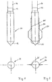
- FIG. 1 shows a torpedo-shaped deep vibrator 11 whose cross-section is pure is circular cylindrical and which reveals a conical tip 12. At the upper end a movable coupling 13 is provided, to which a linkage section 14 followed.
- FIG. 2 a deep vibrator 21 according to the prior art is shown in comparison to FIG. in addition to the matching features of a conical tip 22, a coupling 23 and a linkage section 24, lateral cable guides 25, 26 and overlying radially projecting swords 27, 28 can be seen, the Counteract a twisting of the vibrator in the ground.
- the swords 27, 28 have the shape of radially projecting fins.
Landscapes
- Engineering & Computer Science (AREA)
- Structural Engineering (AREA)
- Life Sciences & Earth Sciences (AREA)
- General Life Sciences & Earth Sciences (AREA)
- Soil Sciences (AREA)
- Environmental & Geological Engineering (AREA)
- Agronomy & Crop Science (AREA)
- Mining & Mineral Resources (AREA)
- Paleontology (AREA)
- Civil Engineering (AREA)
- General Engineering & Computer Science (AREA)
- Investigation Of Foundation Soil And Reinforcement Of Foundation Soil By Compacting Or Drainage (AREA)
- Placing Or Removing Of Piles Or Sheet Piles, Or Accessories Thereof (AREA)
- Earth Drilling (AREA)
- Apparatuses For Generation Of Mechanical Vibrations (AREA)
Abstract
Description
Die Erfindung betrifft ein Verfahren zum Verdichten von Böden mittels eines Tiefenrüttlers, der von einer um eine vertikale Längsachse umlaufenden Unwuchtmasse erregt in den Boden abgesenkt und aus diesem wieder gezogen wird. Tiefenrüttler zur Durchführung des Verfahrens sind mit einem länglich bombenförmigen Gehäuse mit einer Längsachse und einer koaxial im Gehäuse gelagerten motorisch antreibbaren Drehachse sowie einer mit der Drehachse umlaufenden Unwuchtmasse ausgestattet.The invention relates to a method for compacting soils by means of a deep vibrator, that of a circulating about a vertical longitudinal axis imbalance mass energized lowered into the ground and pulled out of this again. deep vibrator for carrying out the method are with an elongated bomb-shaped housing with a longitudinal axis and a coaxially mounted in the housing motor-driven Rotary axis and equipped with the rotation axis circulating imbalance mass.
Das Verdichten von rolligen Böden (Kiese- und Sande) mittels Tiefenrüttlern in großen Tiefen und in beliebiger Mächtigkeit ist erprobt. Die Anwendung des Verfahrens bis in Tiefen von 50 Meter ist bereits ausgeführt. Tiefen von 70 Metern sind angestrebt. Die Rüttlerarbeit erfolgt durch Antrieb einer Unwuchtmasse im vertikal aufgehängten Rüttlergehäuse, die von einem darüber angeordneten Elektro- oder Hydraulikmotor angetrieben wird. Der Tiefenrüttler wird durch Anschrauben eines Rohrstranges, in dem die Versorgungsleitungen verlaufen (Strom, Wasser, Hydrauliköl), für die gewünschte Tiefe hergerichtet. Das so gebildete Aggregat wird an einem Bagger oder einem speziellen Traggerät mit vertikalem Mäkler über ein Stahlseil gehalten und geführt. Der pendelnde und drehbare Aufhängepunkt befindet sich am oberen Ende des Rohrstranges. Am unteren Ende des Rohrstranges ist der Tiefenrüttler mittels einer Gelenkupplung angelenkt. Idealerweise soll der Tiefenrüttler am Anlenkpunkt in Ruhe bleiben und mit der unten liegenden Rüttlerspitze eine Kreisschwingung ausüben. Die Bewegung des Rüttlers wird somit von einem Kegel mit obenliegender Spitze eingehüllt. Die Bewegung des Rüttlers wird von der Umlauffrequenz und der Größe der Unwuchtmasse bestimmt und entspricht nicht notwendig dem vorgenannten Idealfall. Aufgrund der Rotation der Unwuchtmasse kommt es zu einem rückdrehenden Rotationsmoment auf das Rüttlergehäuse, das zu einer Verdrehung des Rüttlers und des Rohrstranges und damit gegenüber dem Mäkler führt. Hierdurch verdrehen sich die Versorgungsleitungen, die dadurch abgeklemmt werden können oder aus ihren Fittings ausreißen können. Dieser Erscheinung ist bisher durch das Anbringen von längsverlaufenden Außenschwertern am Gehäuse des Tiefenrüttlers oder zumindest durch längsverlaufende außengeführte Rohrleitungen nur unzureichend entgegengewirkt worden. Derartige Mittel erhöhen im übrigen den Eindringwiderstand des Tiefenrüttlers in nachteiliger Weise.The compacting of rolling soil (gravels and sands) by means of deep vibrators in large Depths and in any thickness is tested. The application of the procedure to depths of 50 meters is already running. Depths of 70 meters are desired. The vibrator work is done by driving an imbalance mass in vertically suspended Vibrator housing by an electric or hydraulic motor located above is driven. The deep vibrator is by screwing a pipe string, in which the supply lines run (electricity, water, hydraulic oil), for the desired depth prepared. The aggregate thus formed is on an excavator or a special carrying device with a vertical broker held by a steel cable and guided. The swinging and rotating suspension point is located at the top End of the tubing. At the lower end of the tubing is the deep vibrator means articulated a joint coupling. Ideally, the deep vibrator should be at the point of articulation stay calm and with the bottom Rüttlerspitze a circular oscillation exercise. The movement of the vibrator is thus of a cone with overhead Lace shrouded. The movement of the vibrator is determined by the orbital frequency and the size of the unbalanced mass determines and does not necessarily correspond to the aforementioned ideal case. Due to the rotation of the imbalance mass it comes to a reverse rotational moment on the vibrator housing, resulting in a twist the vibrator and the pipe string and thus leads to the leader. As a result, twist the supply lines, which are thereby disconnected can or can tear out of their fittings. This phenomenon is so far by attaching longitudinal external swords to the housing of the deep vibrator or at least by longitudinally guided outside piping only insufficiently counteracted. Incidentally, such agents increase the penetration resistance of the deep vibrator disadvantageously.
Die Verdichtung des Bodens erfolgt von unten nach oben. Nach Absenken des Tiefenrüttlers auf die vorgesehene Endteufe wird er entweder kontinuierlich nach oben gezogen oder aber stufenweise in Schritten von 20 bis 100 cm, wobei er auf jeder Stufe eine Weile von 20 bis 60 Sekunden verharrt. Die Verdichtung des Bodens ist naturgemäß mit einer Volumenverminderung verbunden, die sich an einer Trichterbildung und an konzentrischen Setzrissen um den Trichter an der Geländeoberfläche sowie an einer Neigung der Geländeoberfläche im weiteren zum Trichter hin zeigt. Im bisher bekannten Rüttlerbetrieb ist es üblich, mit einer eingestellten Umlauffrequenz zu arbeiten und die vom Rüttlermotor aufgenommene Leistung zu kontrollieren. Hiermit sollen zum einen unzulässige Belastungen vermieden werden, zum anderen werden Verdichtungsschritte bei nur noch geringer Leistungsaufnahme abgebrochen und der Tiefenrüttler auf die nächste Stufe gezogen.The compaction of the soil takes place from bottom to top. After lowering the deep vibrator on the intended final depth, he is either continuously upward pulled or in stages in increments of 20 to 100 cm, taking on each Step for a while from 20 to 60 seconds. The compaction of the soil is naturally associated with a volume reduction, which is due to a funnel formation and concentric risers around the funnel on the terrain surface and at an inclination of the terrain surface further towards the funnel points. In the previously known vibrator operation, it is customary with a set rotational frequency to work and control the power absorbed by the vibrator motor. This is to be avoided on the one hand unacceptable burdens, on the other Compaction steps are interrupted with only low power consumption and the deep vibrator pulled to the next level.
Aus der DE 26 29 485 A1, der DE 29 48 403 A1 und der DE 32 05 099 A1 sind Tiefenrüttler bekannt, bei denen Mittel vorhanden sind, mit denen die wirksame Unwuchtmasse durch Wechsel der Drehrichtung der Unwuchtmasse verändert werden kann.DE 26 29 485 A1, DE 29 48 403 A1 and DE 32 05 099 A1 are deep vibrators in which there are agents with which the effective imbalance mass be changed by changing the direction of rotation of the imbalance mass can.
Der vorliegenden Erfindung liegt die Aufgabe zugrunde, ein Verfahren bereitzustellen, mit dem die genannten Betriebsstörungen verhindert und das Eindringverhalten des Tiefenrüttlers verbessert werden können. The present invention has for its object to provide a method with which the mentioned malfunctions prevented and the penetration of the deep vibrator can be improved.
Die Lösung hierfür besteht in einem Verfahren, gemäß dem die Unwuchtmasse mit abwechselnder Drehrichtung angetrieben wird, wobei die Drehrichtung in Abhängigkeit von der Verdrehung des Tiefenrüttlers gegenüber dem Mäkler geändert wird. Die entsprechende Verdrehung kann mit geeigneten kontaktlosen Aufnehmern erfaßt werden. Mit diesen Maßnahmen ist sichergestellt, daß die Versorgungsleitungen immer nur in einem so geringen Maße verdreht werden, daß es weder durch die erzeugten Verkürzungen infolge des Ineinanderverdrehens noch durch die Abscherkräfte infolge der Verdrehung als solcher zu Beschädigungen der Versorgungsleitungen kommen kann. Die wirksame Unwuchtmasse bleibt hierbei unverändert.The solution to this consists in a method according to which the imbalance mass with alternating direction of rotation is driven, the direction of rotation depending is changed by the rotation of the deep vibrator against the broker. The corresponding rotation can be detected with suitable contactless sensors become. These measures ensure that the supply lines always be twisted only to such a small extent that it is not generated by the Shortening as a result of the twisting of one another or the shearing forces as a result of the twist as such to damage the supply lines can come. The effective imbalance mass remains unchanged.
Ein geeigneter Tiefenrüttler zur Durchführung des Verfahrens ist dadurch gekennzeichnet, daß er ein Gehäuse von rein rotationssymmetrischer Außenform und einen drehumschaltbaren Antrieb für die Unwuchtmasse aufweist. Mit dieser rein rotationssymmetrischen Außenform erhält der Tiefenrüttler ein verbessertes Eindringverhalten. Die Tatsache, daß es aufgrund des Reaktionsmomentes nun zu einem schnelleren Verdrehen im Bohrloch kommen kann, ist unkritisch, da Überwachungsmittel für den Verdrehungswinkel des Tiefenrüttlers gegenüber dem Mäkler vorgesehen sind und eine vorzugsweise automatisierte Umsteuerung den schadensfreien Betrieb sichert. Mit der Änderung der Drehrichtung der Unwuchtmasse ändert sich die Drehrichtung des Rückdrehmomentes, so daß die aufgetretene Verdrehung wieder aufgehoben wird und die dann eintretende Verdrehung im Gegensinn in sich wiederholender Weise kontrolliert und begrenzt wird. Die wirksame Unwuchtmasse bleibt hierbei unverändert.A suitable deep vibrator for carrying out the method is characterized in that that he a housing of purely rotationally symmetrical outer shape and a rotationally switchable drive for the imbalance mass has. With this purely rotationally symmetric Outside shape of the deep vibrator receives an improved penetration. The fact that it now due to the reaction torque to a faster twisting downhole is uncritical because monitoring means for the twist angle of the deep vibrator opposite the broker are provided and a preferably automated reversal the damage-free Operation secures. Changes with the change of the direction of rotation of the imbalance mass the direction of rotation of the return torque, so that the twist occurred is canceled again and the then entering twist in the opposite direction in itself repeatedly controlled and limited. The effective imbalance mass remains unchanged.
Zeichnungen, die eine zur Durchführung des erfindungsgemäßen Verfahrens geeignete Vorrichtung verdeutlichen, sind nachfolgend beschrieben.
- Figur 1
- zeigt einen Tiefenrüttler in Seitenansicht und im Querschnitt.
- Figur 2
- zeigt einen Tiefenrüttler nach dem Stand der Technik in Seitenansicht und im Querschnitt.
- Figur 3
- zeigt einen Tiefenrüttler mit eingeschraubtem Gestänge, angehängt an einem Kranfahrzeug.
- FIG. 1
- shows a deep vibrator in side view and in cross section.
- FIG. 2
- shows a deep vibrator according to the prior art in side view and in cross section.
- FIG. 3
- shows a deep vibrator with screwed rod, attached to a crane vehicle.
In Figur 1 ist ein torpedoförmiger Tiefenrüttler 11 gezeigt, dessen Querschnitt rein
kreiszylindrisch ist und der eine konische Spitze 12 erkennen läßt. Am oberen Ende
ist eine bewegliche Kupplung 13 vorgesehen, an die sich ein Gestängeabschnitt 14
anschließt.FIG. 1 shows a torpedo-shaped
In Figur 2 ist im Vergleich dazu ein Tiefenrüttler 21 nach dem Stand der Technik gezeigt,
der zusätzlich zu den übereinstimmenden Merkmalen einer konischen Spitze
22, einer Kupplung 23 und eines Gestängeabschnitts 24, seitliche Leitungsführungen
25, 26 und darübergesetzte radial abstehende Schwerter 27, 28 erkennen läßt, die
einem Verdrehen des Rüttlers im Boden entgegenwirken. Die Schwerter 27, 28 haben
die Form radial abstehender Leitflächen.In FIG. 2, a
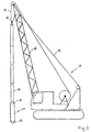
In Figur 3 ist der Tiefenrüttler 11 nach Figur 1 mit den dort bereits genannten Einzelheiten
mit einem viergliedrigen Gestänge 14 verbunden, das über zumindest eine
Umlenkrolle 15 mit dem Seil 16 eines raupenbestückten Kranfahrzeugs 17 verbunden
ist. Das Seil 16 ist zurückgeführt und am Ausleger 18 fest angeschlagen. Die
zumindest eine Umlenkrolle 15 ist verdrehfest mit dem Gestänge 14 verbunden. Ein
weiteres Seil 19 dient nur dem Aufrichten des Auslegers 18.In Figure 3, the
Claims (1)
- A method of compacting soils by means of a depth vibrator (11) which, while being excited by an out-of-balance mass rotating around a vertical longitudinal axis, is lowered into the soil and lifted therefrom, which is suspended at a leader or the like (18) by means of pipeline (14) screwed on via a jointed coupling (13) and by means of a steel rope (16) running in the leader (18) and which is connected to at least one cable or hose line extending as far as the pipeline (14), wherein the out-of-balance mass is driven in alternating directions of rotation,
characterised in that the direction of rotation is changed as a function of the rotation of the depth vibrator (11) relative to the leader (18).
Applications Claiming Priority (2)
| Application Number | Priority Date | Filing Date | Title |
|---|---|---|---|
| DE19930885A DE19930885C2 (en) | 1999-07-05 | 1999-07-05 | Method for controlling a deep vibrator |
| DE19930885 | 1999-07-05 |
Publications (3)
| Publication Number | Publication Date |
|---|---|
| EP1069244A2 EP1069244A2 (en) | 2001-01-17 |
| EP1069244A3 EP1069244A3 (en) | 2002-07-03 |
| EP1069244B1 true EP1069244B1 (en) | 2005-09-28 |
Family
ID=7913657
Family Applications (1)
| Application Number | Title | Priority Date | Filing Date |
|---|---|---|---|
| EP00114397A Expired - Lifetime EP1069244B1 (en) | 1999-07-05 | 2000-07-05 | Method for monitoring a downhole vibrator |
Country Status (3)
| Country | Link |
|---|---|
| EP (1) | EP1069244B1 (en) |
| AT (1) | ATE305537T1 (en) |
| DE (1) | DE19930885C2 (en) |
Cited By (1)
| Publication number | Priority date | Publication date | Assignee | Title |
|---|---|---|---|---|
| CN104358248A (en) * | 2014-11-13 | 2015-02-18 | 中国水电基础局有限公司 | Telescopic guide rod of vibroflotation gravel pile machine |
Families Citing this family (6)
| Publication number | Priority date | Publication date | Assignee | Title |
|---|---|---|---|---|
| DE10232314A1 (en) * | 2002-07-17 | 2004-02-05 | Bauer Spezialtiefbau Gmbh | Vibrating boring tool for hard ground layers has an additional axial vibrator in the driving tip |
| NL1033865C2 (en) * | 2007-05-16 | 2008-11-18 | Van Leeuwen Harmelen Bv Geb | Foundation by vibrating and vibrating. |
| DE102010029010A1 (en) * | 2010-04-16 | 2011-10-20 | Alexander Degen | Deep vibrator arrangement with cutting plate |
| US9494006B2 (en) | 2012-08-14 | 2016-11-15 | Smith International, Inc. | Pressure pulse well tool |
| CN103439909A (en) * | 2013-06-23 | 2013-12-11 | 四川海普工控技术有限公司 | Monitoring method for preventing repeated shutdowns of vibroflots |
| DE102016120382A1 (en) | 2016-10-26 | 2018-04-26 | Gmb Gmbh | Method, principle, control and equipment for carrying out the automatic compression of multiphase grain mixtures |
Family Cites Families (6)
| Publication number | Priority date | Publication date | Assignee | Title |
|---|---|---|---|---|
| NL7508079A (en) * | 1975-07-07 | 1977-01-11 | Kooten Bv V | SOIL VIBRATOR AND METHOD OF INSERTING A SOIL VIBRATOR. |
| DE2948403A1 (en) * | 1979-12-01 | 1981-06-04 | Fritz Pollems KG Spezialtiefbau, 1000 Berlin | Vibrator for ground compaction - with variable operational frequency obtained by varying eccentric rotation and adjusting its centre of gravity |
| DE3105611C2 (en) * | 1981-02-16 | 1984-03-29 | Zoltan Thomas Dipl.-Ing. 7640 Kehl Egey | Method and device for deep compaction |
| DE3205099C2 (en) * | 1981-11-28 | 1984-04-05 | Bilfinger + Berger Bauaktiengesellschaft, 6800 Mannheim | Deep vibrator for compacting the subsoil |
| DE69013136D1 (en) * | 1990-01-11 | 1994-11-10 | Seiko Kogyo K K | Double pipe device for drilling and kneading and method for improving foundation ground with this double pipe device for drilling and kneading. |
| DE19628769C2 (en) * | 1996-07-17 | 1998-06-10 | Bul Sachsen Gmbh | Method and device for deep compaction of binding and non-binding compaction material |
-
1999
- 1999-07-05 DE DE19930885A patent/DE19930885C2/en not_active Expired - Fee Related
-
2000
- 2000-07-05 EP EP00114397A patent/EP1069244B1/en not_active Expired - Lifetime
- 2000-07-05 AT AT00114397T patent/ATE305537T1/en not_active IP Right Cessation
Cited By (2)
| Publication number | Priority date | Publication date | Assignee | Title |
|---|---|---|---|---|
| CN104358248A (en) * | 2014-11-13 | 2015-02-18 | 中国水电基础局有限公司 | Telescopic guide rod of vibroflotation gravel pile machine |
| CN104358248B (en) * | 2014-11-13 | 2016-04-27 | 中国水电基础局有限公司 | The telescopic guide rod of vibro replacement stone column machine |
Also Published As
| Publication number | Publication date |
|---|---|
| EP1069244A3 (en) | 2002-07-03 |
| DE19930885A1 (en) | 2001-02-01 |
| EP1069244A2 (en) | 2001-01-17 |
| ATE305537T1 (en) | 2005-10-15 |
| DE19930885C2 (en) | 2003-04-24 |
Similar Documents
| Publication | Publication Date | Title |
|---|---|---|
| EP3081737B1 (en) | Drilling apparatus for making a borehole with pipe and method for operating a drilling apparatus | |
| DE69823223T2 (en) | METHOD FOR HOLES AND FOUNDING PUNCHES | |
| EP2295646B1 (en) | Drilling equipment and method | |
| DE1634237A1 (en) | Method for producing a tie rod in the ground | |
| DE69612786T2 (en) | Displacement drill and manufacturing method for a ground screw pile | |
| EP2085566A2 (en) | Drilling assembly | |
| DE2157282A1 (en) | Earth drilling method and earth drilling machine | |
| DE1634233A1 (en) | Method for anchoring structures and building elements in the ground with the help of rod anchors | |
| EP1069244B1 (en) | Method for monitoring a downhole vibrator | |
| EP2737132B1 (en) | Method for ground probing | |
| DE1634862A1 (en) | Digging trenches for walls to be laid in the ground | |
| DE3902868C1 (en) | ||
| EP1491716A2 (en) | Method for drilling a borehole and wet boring tool | |
| EP1134319A2 (en) | Method and apparatus for obtaining a cast in situ concrete pile | |
| DE3011263A1 (en) | MACHINE FOR DRILLING IN STONES | |
| DE69710275T2 (en) | Excavator for digging deep trenches | |
| DE1171848B (en) | Device and method for driving a borehole | |
| DE10006973C2 (en) | Rüttelverdränger Snail | |
| AT413422B (en) | METHOD AND DEVICE FOR MEASURING A BOREOOL | |
| DE60011244T2 (en) | DRILLING MACHINE FOR THE PRODUCTION OF LONG DIAMETERS AND LARGE HOUSINGS, AND METHOD FOR CARRYING OUT SUCH DRILLING HOBS | |
| DE2837397A1 (en) | Rotary foundation drilling machine waste removal - involves worm gear on hollow shaft round drill head shaft with blades as conveyors | |
| DE19930884A1 (en) | Sub-soil compacting method uses sub-soil vibrator with flywheel altered in size during lowering/withdrawal to vary impact force | |
| WO2021089603A1 (en) | Method and trench cutting device for creating a trench in the ground | |
| DE1224229B (en) | Method for drilling or extension drilling in the ground and device for carrying out the method | |
| CN2937440Y (en) | Earth boring machine |
Legal Events
| Date | Code | Title | Description |
|---|---|---|---|
| PUAI | Public reference made under article 153(3) epc to a published international application that has entered the european phase |
Free format text: ORIGINAL CODE: 0009012 |
|
| AK | Designated contracting states |
Kind code of ref document: A2 Designated state(s): AT BE CH CY DE DK ES FI FR GB GR IE IT LI LU MC NL PT SE |
|
| AX | Request for extension of the european patent |
Free format text: AL;LT;LV;MK;RO;SI |
|
| RIN1 | Information on inventor provided before grant (corrected) |
Inventor name: KOECHER, JOHANNES, DR. Inventor name: BERG, JOACHIM, DIPL.-ING. |
|
| PUAL | Search report despatched |
Free format text: ORIGINAL CODE: 0009013 |
|
| AK | Designated contracting states |
Kind code of ref document: A3 Designated state(s): AT BE CH CY DE DK ES FI FR GB GR IE IT LI LU MC NL PT SE |
|
| AX | Request for extension of the european patent |
Free format text: AL;LT;LV;MK;RO;SI |
|
| 17P | Request for examination filed |
Effective date: 20021107 |
|
| AKX | Designation fees paid |
Designated state(s): AT CH DE FR GB LI NL |
|
| 17Q | First examination report despatched |
Effective date: 20031216 |
|
| GRAP | Despatch of communication of intention to grant a patent |
Free format text: ORIGINAL CODE: EPIDOSNIGR1 |
|
| RTI1 | Title (correction) |
Free format text: METHOD FOR MONITORING A DOWNHOLE VIBRATOR |
|
| GRAS | Grant fee paid |
Free format text: ORIGINAL CODE: EPIDOSNIGR3 |
|
| RBV | Designated contracting states (corrected) |
Designated state(s): AT CH FR GB LI NL |
|
| REG | Reference to a national code |
Ref country code: DE Ref legal event code: 8566 |
|
| GRAA | (expected) grant |
Free format text: ORIGINAL CODE: 0009210 |
|
| AK | Designated contracting states |
Kind code of ref document: B1 Designated state(s): AT CH FR GB LI NL |
|
| PG25 | Lapsed in a contracting state [announced via postgrant information from national office to epo] |
Ref country code: GB Free format text: LAPSE BECAUSE OF FAILURE TO SUBMIT A TRANSLATION OF THE DESCRIPTION OR TO PAY THE FEE WITHIN THE PRESCRIBED TIME-LIMIT Effective date: 20050928 |
|
| REG | Reference to a national code |
Ref country code: GB Ref legal event code: FG4D Free format text: NOT ENGLISH |
|
| REG | Reference to a national code |
Ref country code: CH Ref legal event code: EP |
|
| GBV | Gb: ep patent (uk) treated as always having been void in accordance with gb section 77(7)/1977 [no translation filed] |
Effective date: 20050928 |
|
| PG25 | Lapsed in a contracting state [announced via postgrant information from national office to epo] |
Ref country code: LI Free format text: LAPSE BECAUSE OF NON-PAYMENT OF DUE FEES Effective date: 20060731 Ref country code: CH Free format text: LAPSE BECAUSE OF NON-PAYMENT OF DUE FEES Effective date: 20060731 |
|
| PLBE | No opposition filed within time limit |
Free format text: ORIGINAL CODE: 0009261 |
|
| STAA | Information on the status of an ep patent application or granted ep patent |
Free format text: STATUS: NO OPPOSITION FILED WITHIN TIME LIMIT |
|
| 26N | No opposition filed |
Effective date: 20060629 |
|
| EN | Fr: translation not filed | ||
| PG25 | Lapsed in a contracting state [announced via postgrant information from national office to epo] |
Ref country code: FR Free format text: LAPSE BECAUSE OF FAILURE TO SUBMIT A TRANSLATION OF THE DESCRIPTION OR TO PAY THE FEE WITHIN THE PRESCRIBED TIME-LIMIT Effective date: 20061124 |
|
| REG | Reference to a national code |
Ref country code: CH Ref legal event code: PL |
|
| PG25 | Lapsed in a contracting state [announced via postgrant information from national office to epo] |
Ref country code: AT Free format text: LAPSE BECAUSE OF NON-PAYMENT OF DUE FEES Effective date: 20060705 |
|
| PG25 | Lapsed in a contracting state [announced via postgrant information from national office to epo] |
Ref country code: FR Free format text: LAPSE BECAUSE OF FAILURE TO SUBMIT A TRANSLATION OF THE DESCRIPTION OR TO PAY THE FEE WITHIN THE PRESCRIBED TIME-LIMIT Effective date: 20050928 |
|
| PGFP | Annual fee paid to national office [announced via postgrant information from national office to epo] |
Ref country code: NL Payment date: 20170726 Year of fee payment: 18 |
|
| REG | Reference to a national code |
Ref country code: NL Ref legal event code: MM Effective date: 20180801 |
|
| PG25 | Lapsed in a contracting state [announced via postgrant information from national office to epo] |
Ref country code: NL Free format text: LAPSE BECAUSE OF NON-PAYMENT OF DUE FEES Effective date: 20180801 |