EP1069236A2 - Regulating the pressure in a headbox - Google Patents
Regulating the pressure in a headbox Download PDFInfo
- Publication number
- EP1069236A2 EP1069236A2 EP00110345A EP00110345A EP1069236A2 EP 1069236 A2 EP1069236 A2 EP 1069236A2 EP 00110345 A EP00110345 A EP 00110345A EP 00110345 A EP00110345 A EP 00110345A EP 1069236 A2 EP1069236 A2 EP 1069236A2
- Authority
- EP
- European Patent Office
- Prior art keywords
- headbox
- pressure
- distribution device
- sensor
- control
- Prior art date
- Legal status (The legal status is an assumption and is not a legal conclusion. Google has not performed a legal analysis and makes no representation as to the accuracy of the status listed.)
- Withdrawn
Links
Images


Classifications
-
- D—TEXTILES; PAPER
- D21—PAPER-MAKING; PRODUCTION OF CELLULOSE
- D21F—PAPER-MAKING MACHINES; METHODS OF PRODUCING PAPER THEREON
- D21F1/00—Wet end of machines for making continuous webs of paper
- D21F1/02—Head boxes of Fourdrinier machines
- D21F1/024—Details of the feed chamber
-
- D—TEXTILES; PAPER
- D21—PAPER-MAKING; PRODUCTION OF CELLULOSE
- D21F—PAPER-MAKING MACHINES; METHODS OF PRODUCING PAPER THEREON
- D21F1/00—Wet end of machines for making continuous webs of paper
- D21F1/02—Head boxes of Fourdrinier machines
-
- D—TEXTILES; PAPER
- D21—PAPER-MAKING; PRODUCTION OF CELLULOSE
- D21F—PAPER-MAKING MACHINES; METHODS OF PRODUCING PAPER THEREON
- D21F1/00—Wet end of machines for making continuous webs of paper
- D21F1/06—Regulating pulp flow
Definitions
- the invention relates to a control device for control, preferably for fine control, of pressure in a headbox with a headbox nozzle a paper or board machine hydraulically connected space, with at least a feed line for a fiber suspension, at least one distribution device for the fiber suspension and at least one derivative for the Excess fiber suspension from the distribution device (recirculation line). Furthermore, the invention relates to a control device according to the invention feasible procedure.
- An essential quality factor of a paper or board web is that Uniformity of the properties, such as the weight per unit area or the formation, the manufactured track.
- Uniformity of the properties such as the weight per unit area or the formation, the manufactured track.
- CD machine width
- MD longitudinal direction
- a major disruptive factor that is mainly in the longitudinal direction affects, is the temporal variation in the amount of ejected through the headbox Fibrous suspension, which in turn directly with the course of time the pressure in the headbox nozzle and the pulp suspension feed system related.
- the pressure is made up of a dynamic and a static portion, which form the total pressure in the headbox nozzle.
- the task is characterized by the features of the device claim 1 and Features of the method claim 14 solved.
- the inventors have recognized that it is possible to adjust the time fluctuations of the Throughput of fiber suspension through a headbox very sensitive to influence that a control loop between the measured pressure in a room connected to the headbox nozzle, for example in the headbox itself, in particular in the headbox nozzle, or in a feed line of the fiber suspension in the headbox or in front of a throttle device further derivation from the distribution device.
- a control loop between the measured pressure in a room connected to the headbox nozzle, for example in the headbox itself, in particular in the headbox nozzle, or in a feed line of the fiber suspension in the headbox or in front of a throttle device further derivation from the distribution device.
- This considered pressure more precisely the pressure fluctuations, both the Total pressure, consisting of the dynamic and static pressure, or the static pressure alone or the static pressure together with one after Bernoulli calculated dynamic pressure can be used.
- the temporal Pressure fluctuations are in the total pressure as well as in the dynamic and recognizable in the static pressure component, measurable and usable for regulation.
- the headbox nozzle On the preferred location for pressure measurement is naturally the headbox nozzle itself, however, measurements can be taken in the overall fiber suspension supply of the headbox or other hydraulically coupled to the headbox nozzle Rooms can be used.
- the space in which the pressure is kept constant is preferably the headbox nozzle itself.
- due to the hydraulic connection also has another space in the area of the headbox, such as the distribution device or the feed of the fiber suspension after a conveyor unit or further derivation from the distribution device be used in front of a throttle device.
- the inventors propose a control device for control, preferably for fine control, the pressure in one with a headbox nozzle a headbox of a paper or board machine hydraulically connected Space, with at least one supply line for a fiber suspension, at least a distribution device for the fiber suspension and at least one discharge line for the excess fiber suspension from the distribution device (Recirculation line) to further develop that at least one sensor to measure the pressure in the hydraulically connected to the headbox nozzle Space is provided and at least one in the supply line a speed-controlled and acted upon by the at least one sensor Pump (headbox pump) is located by changing its speed controls the pressure over time in the headbox nozzle.
- This gives the advantage that by means of an inexpensive unit in the form of a speed-controlled Pump the flow rate in the supply line to the headbox nozzle and thus the pressure prevailing in the headbox nozzle and its time Course can be regulated with constant cross sections.
- the headbox nozzle is particularly suitable as a measuring point for the pressure measurement sensor. however also the supply line, the discharge line (recirculation line) or the Distribution device.
- a particularly advantageous embodiment of the invention results when in the at least one distribution device and / or at least one feed line at least one further derivative with at least one of the at least one a sensor acted throttle device is located by opening and Closing regulates the time course of the pressure in the headbox nozzle.
- This further derivation with adjustable throttle device in the form of a subordinate Control loop has the advantage that it can be attached to the inlet into the Distribution device the excess fiber suspension very quickly and effectively dissipates from the distribution device, and this with low investment and operating costs.
- At least one further sensor is used Measurement of the pressure provided in the at least one distribution device, wherein in the at least one distribution device and / or at least one Supply at least one further derivation with at least one of the at least another sensor acted throttle device is located by opening and closing the pressure over time in the headbox nozzle regulates.
- the inventors propose a control device that a time filter is provided in the control circuit which is exclusively disturbances with a time constant t of greater equal to half a second, preferably greater than or equal to one second, for Fine control allows.
- the time interval between two is used as the time constant t consecutive disorders viewed both periodically and stochastically can be done.
- a very sensitive throttle device for example, is advantageous a special throttle valve known per se, in particular a control valve, which is very sensitive to the flow rate in a certain range regulates, but does not allow complete curtailment.
- a control valve which is very sensitive to the flow rate in a certain range regulates, but does not allow complete curtailment.
- DE 43 05 688 A1 PA04956 DE
- DE 44 02 515 A1 PA10048 DE
- the known one Distribution device to be a cross or central distributor.
- the invention Control device a well-known single or multi-layer headbox be assigned.
- This fine control according to the invention ensures that - due to the tests now carried out - instead of the currently usual, no longer settable Pressure fluctuations in the range of 3% to 4%, at best 2%, now maximum pressure fluctuations in the range of ⁇ 1%, often ⁇ 0.5%, and partially even only ⁇ 0.3% can be realized.
- the inventors continue to propose a method to control, preferably fine control, the pressure in one with a Headbox nozzle of a headbox of a paper or board machine hydraulic connected space, with at least one feed line for a fiber suspension, at least one distribution device for the fiber suspension and at least one derivation for the excess fiber suspension from the Distribution device (recirculation line), which the following process steps comprises: measuring the pressure in at least one with the headbox nozzle hydraulically connected space, preferably in the headbox nozzle and Regulation of the speed of the at least one in the feed line for the fiber suspension attached pump (headbox pump) depending on the measured Print.
- the pressure to be regulated lies, for example, in the supply line, the distribution device, the recirculation line or preferably in the headbox nozzle.
- the headbox nozzle is particularly suitable for the pressure measurement sensor, however also the supply line, the discharge line (recirculation line) or the distribution device.
- a particularly advantageous method of the invention results if the temporal Course of the pressure in the headbox nozzle also by opening and closing at least one in at least one further, in the at least one distribution device and / or attached at least one feed line integrated lead Throttle device, which is acted upon by the at least one sensor is regulated.
- This procedure using another derivative with adjustable throttle device in the form of a subordinate control loop the advantage that they are very close to the inlet in the distributor the excess fiber suspension from the distribution device quickly and effectively dissipates.
- Another method according to the invention provides that the time course the pressure in the headbox nozzle also by opening and closing at least one in at least one other, in the at least one distribution device and / or attached at least one feed line integrated lead Throttle device by at least one other, in the at least one Distributor attached sensor is acted upon, is regulated.
- the control engineering advantage results in the shortest possible dead time thanks to a subordinate control loop with its own sensor at low costs.
- Fine control only faults with a time constant t greater than or equal half a second, preferably one second.
- the distribution device used can be in the feed line for the fiber suspension be both a cross and a central distributor, as in the modern paper or board machines that work according to the dilution principle, for controlling the basis weight and fiber orientation cross profile is used.
- the distribution device can be used both for the fiber suspension and equipped for the white water with the control according to the invention become.
- time filter specified above is in itself known way electronically or by appropriate computer programs can be realized.
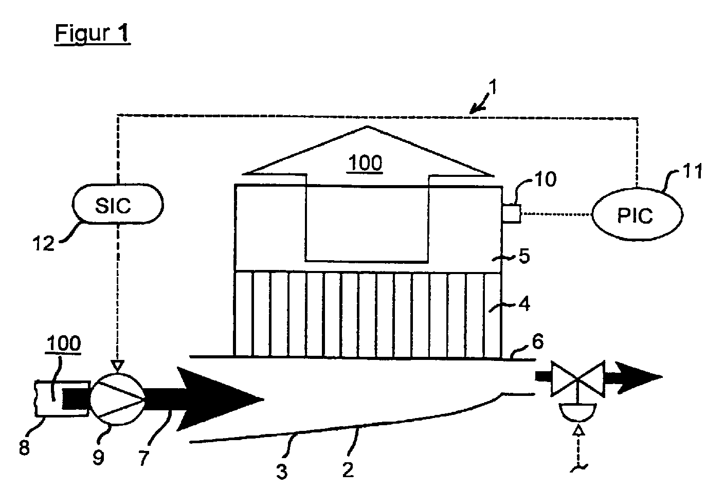
- FIG. 1 shows a control device according to the invention using the example of a Headbox 1, consisting of a distribution device 2 in the form of a cross distributor 3, a turbulence generator 4 and a headbox nozzle 5 that machine-width the pulp suspension 100 on sieve, not shown, or distributed between two sieves, not shown. Further there is at least one derivative 6 at the end of the distribution device 2 (Recirculation line) through which the in the distribution device 2 possibly excess fiber suspension 100 removed becomes; the derivation 6 can also consist of several small derivation channels, the flow cross-sections and thus the flow rates individually, in Groups or in their entirety controlled or regulated, for example by a manually operated manual valve or, as shown in Figure 1, by a controlled Control valve, can be.
- a distribution device 2 in the form of a cross distributor 3, a turbulence generator 4 and a headbox nozzle 5 that machine-width the pulp suspension 100 on sieve, not shown, or distributed between two sieves, not shown.
- the derivation 6 can also
- the fiber suspension 100 which is shown as arrow 7 is shown, passes through a feed line 8, in which a speed-controlled pump 9th (Headbox pump) is arranged in the cross distributor 3 and becomes mostly via the turbulence generator 4 to the headbox nozzle 5, in the it creates a pressure.
- the pressure especially a temporal change in the Pressure is measured by a sensor 10 and as a measured variable to the two control units 11 and 12 (PIC and SIC) connected in series are forwarded, which according to the laws of a control loop known per se make a possible correction to the speed of the speed-controlled pump 9 and thus the flow rate of fiber suspension and the prevailing Determine temporal pressures in the headbox with unchanged cross sections.
- FIG. 1a shows a control according to Figure 1, but is additional in addition to the speed-controlled pump 9 in the designed as a cross distributor 3 Distributor 2 attached a further derivative 13, the flow rate is regulated by means of a throttle device 14.
- the throttle device 14 receives their control variables directly from the two control units connected in series 11 and 12 (PIC and SIC), which, as already mentioned above, their measured variables again from the sensor 10 which is in the headbox nozzle 5 of the headbox 1 is attached, receives, In this embodiment, the rough control of the Pressure in the headbox nozzle 5 by the speed-controlled pump 9, while the fine control exclusively via the throttle device 14 is realized in the further derivation 13.
- PIC and SIC two control units connected in series 11 and 12
- Control device for the flow of excess Fibrous suspension 100 is in this figure as a manually operated manual valve executed; the leads 6 can also be designed as described in FIG. 1 his.
- the fiber suspension 100 which is shown as arrow 7 is represented by a feed line 8, in which a speed-controlled pump 9 (Headbox pump) is arranged, enters the cross-distributor 3.
- FIG. 1b shows a control according to Figure 1, but is additional in addition to the speed-controlled pump 9 in the designed as a cross distributor 3 Distributor 2 attached a further derivative 13, the flow rate is regulated by means of a throttle device 14.
- the throttle device 14 receives their controlled variables directly from one of the control unit 15 (PIC), which their measured variables from a sensor 16, which is attached in the distribution device 2 of the headbox 1 is received.
- PIC control unit 15
- sensor 16 which is attached in the distribution device 2 of the headbox 1
- the rough regulation of Pressure in the headbox 5 by the speed-controlled already described above Pump 9 together with control circuit components (attached to the headbox nozzle 5 Sensor 10, control units 11 and 12) made during the Fine control exclusively via the throttle device 14 in the further derivation 13 is realized.
- fluctuations in larger intervals of e.g. Viewed 1.5 seconds while fine tuning the fluctuations occurring at short intervals ( ⁇ 1.5 s) are accepted.
- FIG. 2 shows a pressure control according to the invention on a dilution water-regulated headbox 1 with a distribution device 2.1 for the fibrous suspension 100 and a distribution device 2.2 for the white water 101 as a dilution strand.
- fiber suspension 100 which is shown as arrow 7.1
- the speed-controlled pump 9.1 headbox pump
- the white water 101 which is shown as arrow 7.2
- the speed-controlled pump 9.2 of the distribution device 2.2 is supplied.
- the flow rate of white water 101 is measured in the feed line 8.2 by means of a flow meter 20 and passed on as a measured variable to the two control units 12.2 and 12.3 (FIC and SIC) connected in series, which, as already described for the fiber suspension 100, according to the laws of one make a possible correction to the speed of the speed-controlled pump 9.2 in a known control circuit and thus determine the delivery rate of white water 101.
- FIG. 2 it can also be seen that at least one further discharge line 13.1 and 13.2 are attached to the distribution devices 2.1 and 2.2 designed as cross distributors 3, the flow rates of which can be regulated by means of a respective throttle device 14.1 and 14.2.
- the throttle devices 14.1 and 14.2 receive their controlled variables directly from the respective control units 15.1 and 15.2 (PIC), which receive their measured variables from their associated sensors 16.1 and 16.2, which in turn are attached in their distributing devices 2.1 and 2.2 of the headbox 1.
- PIC control units 15.1 and 15.2
- the rough control of the pressure in the headbox nozzle 5 is carried out by the above-described speed-controlled pump 9.1 together with control circuit components (sensor 10, control units 11 and 12.1 attached to the headbox nozzle 5), while the fine controls are carried out exclusively via the throttle devices 14.1 and 14.2 in the further derivatives 13.1 and 13.2 are realized.
- FIG. 3 shows a further, modern variant of a fiber suspension supply system for a headbox 1 with a central distributor 19 and the control according to the invention similar to Figure 1b.
- the supplied pulp suspension 100 which is shown as arrow 7, through a feed line 8 to a central distributor 19 and from there via a large number of feeds 17.1 to 17.5, which are not shown here
- Cross section control are regulated, headed into the headbox 1.
- 17.1 to 17.5 are regulated white water supplies 18.1 to for each feed 18.5 shown, which are also connected to the cross profile control and in a manner known per se, the cross profile of the paper or Set the cardboard web.
- the coarse control is speed-controlled in the supply line 8 Pump 9 together with control circuit components (attached to the headbox nozzle 5 Sensor 10, control units 11 and 12) made during the fine control based on that measured in the central distributor 19 by means of a sensor 16 Pressure exclusively on the attached in the further derivation 13 and throttle device 14 controlled by the control unit 15 is realized.
- a valve is attached that in a known manner as a manual valve (manual actuation) or as a control valve (actuation by means of a control circuit) can be executed.
- a control device and an overall Process for regulating the pressure in the headbox nozzle of a headbox a paper or board machine which allow a very fine correction of the pressure in the headbox nozzle and thus the throughput to make fiber suspension through a headbox.
Landscapes
- Paper (AREA)
Abstract
Regelvorrichtung zur Regelung, vorzugsweise zur Feinregelung, des Druckes in
einem mit einer Stoffauflaufdüse (5) eines Stoffauflaufes (1) einer Papier- oder
Kartonmaschine hydraulisch verbundenen Raum, mit mindestens einer Zuleitung
(8) für eine Faserstoffsuspension (100), mindestens einer Verteilvorrichtung (2) für
die Faserstoffsuspension (100) und mindestens einer Ableitung (6) für die überschüssige
Faserstoffsuspension (100) aus der Verteilvorrichtung (Rezirkulationsleitung)
(2), wobei mindestens ein Sensor (10) zur Messung des Druckes in dem
mit der Stoffauflaufdüse (5) hydraulisch verbundenen Raum vorgesehen ist und
sich in der mindestens einen Zuleitung (8) mindestens eine von dem mindestens
einen Sensor (10) beaufschlagte und drehzahlgeregelte Pumpe (Stoffauflaufpumpe)
(9) befindet, die durch Änderung ihrer Drehzahl den zeitlichen Verlauf des
Druckes in der Stoffauflaufdüse (5) regelt, und ein mit der Regelvorrichtung durchführbares
Regelverfahren.
Description
Die Erfindung betrifft eine Regelvorrichtung zur Regelung, vorzugsweise zur Feinregelung, des Druckes in einem mit einer Stoffauflaufdüse eines Stoffauflaufes einer Papier- oder Kartonmaschine hydraulisch verbundenen Raum, mit mindestens einer Zuleitung für eine Fasersuspension, mindestens einer Verteilvorrichtung für die Faserstoffsuspension und mindestens einer Ableitung für die überschüssige Faserstoffsuspension aus der Verteilvorrichtung (Rezirkulationsleitung). Weiterhin betrifft die Erfindung ein mit der erfindungsgemäßen Regelvorrichtung durchführbares Verfahren.The invention relates to a control device for control, preferably for fine control, of pressure in a headbox with a headbox nozzle a paper or board machine hydraulically connected space, with at least a feed line for a fiber suspension, at least one distribution device for the fiber suspension and at least one derivative for the Excess fiber suspension from the distribution device (recirculation line). Furthermore, the invention relates to a control device according to the invention feasible procedure.
Ein wesentlicher Qualitätsfaktor einer Papier- oder Kartonbahn liegt in der Gleichmäßigkeit der Eigenschaften, wie zum Beispiel dem Flächengewicht oder der Formation, der hergestellten Bahn. Im Herstellungsprozeß einer solchen Bahn treten zahlreiche Störfaktoren auf, welche die Gleichmäßigkeit der Eigenschaften sowohl über die Maschinenbreite (CD) hinweg, als auch in Längsrichtung (MD) beeinflussen. Ein wesentlicher Störfaktor, der sich hauptsächlich in Längsrichtung auswirkt, ist die zeitliche Schwankung der Menge der durch den Stoffauflauf ausgestoßenen Faserstoffsuspension, die wiederum direkt mit dem zeitlichen Verlauf des Druckes in der Stoffauflaufdüse und dem Faserstoffsuspensionszuführungssystem zusammenhängt. Der Druck setzt sich aus einem dynamischen und einem statischen Anteil zusammen, die den Gesamtdruck in der Stoffauflaufdüse bilden. Druckschwankungen führen zu Schwankungen bei der pro Zeiteinheit ausgestoßenen Menge an Faserstoffsuspension durch den Auslaufspalt der Stoffauflaufdüse und damit zu Flächengewichtsänderungen und Schwankungen im Flächengewichtslängsprofil des produzierten Papiers bzw. Kartons. Aus diesem Grunde wird in modernen Papier- oder Kartonmaschinen die zugeführte Faserstoffsuspension zum Stoffauflauf möglichst genau geregelt.An essential quality factor of a paper or board web is that Uniformity of the properties, such as the weight per unit area or the formation, the manufactured track. In the manufacturing process of such a web there are numerous disruptive factors that affect the uniformity of the properties both across the machine width (CD) and in the longitudinal direction (MD) influence. A major disruptive factor that is mainly in the longitudinal direction affects, is the temporal variation in the amount of ejected through the headbox Fibrous suspension, which in turn directly with the course of time the pressure in the headbox nozzle and the pulp suspension feed system related. The pressure is made up of a dynamic and a static portion, which form the total pressure in the headbox nozzle. Pressure fluctuations lead to fluctuations in the output per unit of time Amount of fiber suspension through the outlet gap of the headbox nozzle and thus to changes in basis weight and fluctuations in the basis weight longitudinal profile of the paper or cardboard produced. For this Basically, the fiber suspension supplied is used in modern paper or board machines Regulated for the headbox as precisely as possible.
Aus den beiden deutschen Offenlegungsschriften DE 197 36 047 A1 (PA10611 DE) und DE 197 36 048 A1 (PA10605 DE) der Anmelderin ist sowohl eine Regelvorrichtung als auch ein Regelverfahren bekannt, bei denen das Flächengewichtslängsprofil der Papier- oder Kartonbahn über die Messung des Flächengewichts der Papier- oder Kartonbahn und anschließender Drehzahlregulierung einer Förderpumpe in der Zuleitung zum Stoffauflauf geregelt wird.From the two German patent applications DE 197 36 047 A1 (PA10611 DE) and DE 197 36 048 A1 (PA10605 DE) of the applicant is both a control device also known as a control method in which the basis weight longitudinal profile the paper or cardboard web by measuring the basis weight the paper or cardboard web and subsequent speed regulation a feed pump is regulated in the feed line to the headbox.
Der Nachteil einer solchen Regelung besteht darin, daß die Regelung einerseits relativ träge ist und andererseits aufgrund der Trägheit des Schaufelrades der Förderpumpe nur relativ grobe Korrekturen möglich sind. Grob bedeutet in diesem Zusammenhang, daß durch die bisherige Regelung die Druckschwankungen Δp auf einen Bereich von 4% bis 3%, bestenfalls 2%, herunterzuregeln sind. Hierbei ist zu beachten, daß Druckschwankungen um so besser ausgeregelt werden können, je größer ihre Zeitkonstante t, daß heißt der zeitliche Abstand zwischen zwei aufeinanderfolgenden Störungen, ist. Je kürzer die Störungen erfolgen, um so schlechter und weniger genau sind sie auszugleichen.The disadvantage of such a regulation is that the regulation on the one hand is relatively sluggish and on the other hand due to the inertia of the impeller Feed pump only relatively rough corrections are possible. Roughly means in this Context that the pressure fluctuations Δp down to a range of 4% to 3%, at best 2%. Here it should be noted that pressure fluctuations can be regulated the better the greater their time constant t, that is to say the time interval between two successive disturbances. The shorter the disturbances, the more they are worse and less precise to compensate.
Es ist also Aufgabe der Erfindung, eine Regelvorrichtung und ein Verfahren zur Verbesserung des Flächengewichtslängsprofiles durch Regelung des Druckes in einem mit der Stoffauflaufdüse eines Stoffauflaufes einer Papier- oder Kartonmaschine hydraulisch verbundenen Raum oder Kanal anzugeben, welche/welches es erlaubt, eine sehr feine (zeitlich und absolut) und schnelle Korrektur des Durchsatzes an Faserstoffsuspension durch einen Stoffauflauf vorzunehmen.It is therefore an object of the invention to provide a control device and a method for Improvement of the basis weight profile by regulating the pressure in one with the headbox nozzle of a headbox of a paper or board machine hydraulically connected room or duct to indicate which / which it allows a very fine (temporal and absolute) and quick correction the throughput of fiber suspension through a headbox.
Die Aufgabe wird durch die Merkmale des Vorrichtungsanspruches 1 und die
Merkmale des Verfahrensanspruches 14 gelöst.The task is characterized by the features of the
Die Erfinder haben erkannt, daß es möglich ist, die zeitlichen Schwankungen des Durchsatzes an Faserstoffsuspension durch einen Stoffauflauf sehr feinfühlig dadurch zu beeinflussen, daß ein Regelkreis zwischen dem gemessenen Druck in einem mit der Stoffauflaufdüse verbunden Raum, also zum Beispiel im Stoffauflauf selbst, insbesondere in der Stoffauflaufdüse, oder in einer Zuleitung der Faserstoffsuspension in den Stoffauflauf oder vor einer Drosselvorrichtung in der weiteren Ableitung aus der Verteilvorrichtung, aufgebaut wird. Bei dem hierbei betrachteten Druck, genauer gesagt den Druckschwankungen, kann sowohl der Gesamtdruck, bestehend aus dem dynamischen und statischen Druck, oder der statische Druck alleine oder auch der statische Druck zusammen mit einem nach Bernoulli berechneten dynamischen Druck verwendet werden. Die zeitlichen Druckschwankungen sind sowohl im Gesamtdruck, als auch im dynamischen und im statischen Druckanteil erkennbar, meßbar und zur Regelung verwendbar. Ein bevorzugter Ort zur Druckmessung ist naturgemäß die Stoffauflaufdüse selbst, jedoch können Messungen in der gesamten Versorgung mit Faserstoffsuspension des Stoffauflaufes oder an sonstigen mit der Stoffauflaufdüse hydraulisch gekoppelten Räumen genutzt werden. Der Raum, in dem der Druck konstant gehalten werden soll, ist vorzugsweise die Stoffauflaufdüse selbst. Jedoch kann aufgrund der hydraulischen Verbindung auch ein sonstiger Raum im Bereich des Stoffauflaufes, wie zum Beispiel die Verteilvorrichtung oder die Zuleitung der Faserstoffsuspension nach einem Förderaggregat oder die weitere Ableitung aus der Verteilvorrichtung vor einer Drosselvorrichtung hierzu verwendet werden.The inventors have recognized that it is possible to adjust the time fluctuations of the Throughput of fiber suspension through a headbox very sensitive to influence that a control loop between the measured pressure in a room connected to the headbox nozzle, for example in the headbox itself, in particular in the headbox nozzle, or in a feed line of the fiber suspension in the headbox or in front of a throttle device further derivation from the distribution device. With this considered pressure, more precisely the pressure fluctuations, both the Total pressure, consisting of the dynamic and static pressure, or the static pressure alone or the static pressure together with one after Bernoulli calculated dynamic pressure can be used. The temporal Pressure fluctuations are in the total pressure as well as in the dynamic and recognizable in the static pressure component, measurable and usable for regulation. On the preferred location for pressure measurement is naturally the headbox nozzle itself, however, measurements can be taken in the overall fiber suspension supply of the headbox or other hydraulically coupled to the headbox nozzle Rooms can be used. The space in which the pressure is kept constant is preferably the headbox nozzle itself. However, due to the hydraulic connection also has another space in the area of the headbox, such as the distribution device or the feed of the fiber suspension after a conveyor unit or further derivation from the distribution device be used in front of a throttle device.
Demgemäß schlagen die Erfinder vor, eine Regelvorrichtung zur Regelung, vorzugsweise zur Feinregelung, des Druckes in einem mit einer Stoffauflaufdüse eines Stoffauflaufes einer Papier- oder Kartonmaschine hydraulisch verbundenen Raum, mit mindestens einer Zuleitung für eine Faserstoffsuspension, mindestens einer Verteilvorrichtung für die Faserstoffsuspension und mindestens einer Ableitung für die überschüssige Faserstoffsuspension aus der Verteilvorrichtung (Rezirkulationsleitung) dahingehend weiterzuentwickeln, daß mindestens ein Sensor zur Messung des Druckes in dem mit der Stoffauflaufdüse hydraulisch verbundenen Raum vorgesehen ist und sich in der mindestens einen Zuleitung mindestens eine von dem mindestens einen Sensor beaufschlagte und drehzahlgeregelte Pumpe (Stoffauflaufpumpe) befindet, die durch Änderung ihrer Drehzahl den zeitlichen Verlauf des Druckes in der Stoffauflaufdüse regelt. Hierdurch ergibt sich der Vorteil, daß mittels einer kostengünstigen Baueinheit in Form einer drehzahlgeregelten Pumpe die Durchflußmenge in der Zuleitung zur Stoffauflaufdüse und damit der in der Stoffauflaufdüse herrschende Druck und dessen zeitlicher Verlauf bei konstanten Querschnitten geregelt werden kann.Accordingly, the inventors propose a control device for control, preferably for fine control, the pressure in one with a headbox nozzle a headbox of a paper or board machine hydraulically connected Space, with at least one supply line for a fiber suspension, at least a distribution device for the fiber suspension and at least one discharge line for the excess fiber suspension from the distribution device (Recirculation line) to further develop that at least one sensor to measure the pressure in the hydraulically connected to the headbox nozzle Space is provided and at least one in the supply line a speed-controlled and acted upon by the at least one sensor Pump (headbox pump) is located by changing its speed controls the pressure over time in the headbox nozzle. This gives the advantage that by means of an inexpensive unit in the form of a speed-controlled Pump the flow rate in the supply line to the headbox nozzle and thus the pressure prevailing in the headbox nozzle and its time Course can be regulated with constant cross sections.
Als Meßort für den Sensor zur Druckmessung eignet sich besonders die Stoffauflaufdüse, jedoch auch die Zuleitung, die Ableitung (Rezirkulationsleitung) oder die Verteilvorrichtung.The headbox nozzle is particularly suitable as a measuring point for the pressure measurement sensor. however also the supply line, the discharge line (recirculation line) or the Distribution device.
Eine besonders vorteilhafte Ausgestaltung der Erfindung ergibt sich, wenn sich in der mindestens einen Verteilvorrichtung und/oder mindestens einen Zuleitung mindestens eine weitere Ableitung mit mindestens einer von dem mindestens einen Sensor beaufschlagten Drosselvorrichtung befindet, die durch Öffnen und Schließen den zeitlichen Verlauf des Druckes in der Stoffauflaufdüse regelt. Diese weitere Ableitung mit regelbarer Drosselvorrichtung in Form eines unterlagerten Regelkreises erbringt den Vorteil, daß sie bei naher Anbringung am Einlauf in die Verteilvorrichtung sehr schnell und effektiv die überschüssige Faserstoffsuspension aus der Verteilvorrichtung abführt, und dies bei weiterhin niedrigen Investitions- und Betriebskosten.A particularly advantageous embodiment of the invention results when in the at least one distribution device and / or at least one feed line at least one further derivative with at least one of the at least one a sensor acted throttle device is located by opening and Closing regulates the time course of the pressure in the headbox nozzle. This further derivation with adjustable throttle device in the form of a subordinate Control loop has the advantage that it can be attached to the inlet into the Distribution device the excess fiber suspension very quickly and effectively dissipates from the distribution device, and this with low investment and operating costs.
In weiterer Ausgestaltung der Erfindung ist mindestens ein weiterer Sensor zur Messung des Druckes in der mindestens einen Verteilvorrichtung vorgesehen, wobei sich in der mindestens einen Verteilvorrichtung und/oder mindestens einen Zuleitung mindestens eine weitere Ableitung mit mindestens einer von dem mindestens einen weiteren Sensor beaufschlagten Drosselvorrichtung befindet, die durch Öffnen und Schließen den zeitlichen Verlauf des Druckes in der Stoffauflaufdüse regelt. Durch diesen weiteren Sensor in der Verteilvorrichtung wird der gewünschte regelungstechnische Vorteil einer möglichst kurzen Totzeit durch einen unterlagerten Regelkreis mit eigenem Sensor bei geringen Kosten bestmöglichst erreicht.In a further embodiment of the invention, at least one further sensor is used Measurement of the pressure provided in the at least one distribution device, wherein in the at least one distribution device and / or at least one Supply at least one further derivation with at least one of the at least another sensor acted throttle device is located by opening and closing the pressure over time in the headbox nozzle regulates. By means of this further sensor in the distribution device, the desired control engineering advantage of the shortest possible dead time a subordinate control loop with its own sensor as low as possible reached.
Entsprechend einer besonders vorteilhaften Ausführung der erfindungsgemäßen Regelvorrichtung schlagen die Erfinder vor, daß im Regelkreises ein Zeitfilter vorgesehen ist, welches ausschließlich Störungen mit einer Zeitkonstante t von größer gleich einer halben Sekunde, vorzugsweise größer gleich einer Sekunde, zur Feinregelung zuläßt. Als Zeitkonstante t wird der zeitliche Abstand zwischen zwei aufeinanderfolgenden Störungen angesehen, die sowohl periodisch als auch stochastisch erfolgen können.According to a particularly advantageous embodiment of the invention The inventors propose a control device that a time filter is provided in the control circuit which is exclusively disturbances with a time constant t of greater equal to half a second, preferably greater than or equal to one second, for Fine control allows. The time interval between two is used as the time constant t consecutive disorders viewed both periodically and stochastically can be done.
Vorteilhaft ist die Auswahl einer sehr feinfühligen Drosselvorrichtung, zum Beispiel einem speziellen, an sich bekannten Drosselventil, insbesondere einem Stellventil, welches zwar die Durchflußmenge in einem gewissen Bereich sehr feinfühlig regelt, jedoch keine vollständige Abregelung ermöglicht. In diesem Zusammenhang wird beispielsweise auf die Patentanmeldungen DE 43 05 688 A1 (PA04956 DE) und DE 44 02 515 A1 (PA10048 DE) der Anmelderin verwiesen.The selection of a very sensitive throttle device, for example, is advantageous a special throttle valve known per se, in particular a control valve, which is very sensitive to the flow rate in a certain range regulates, but does not allow complete curtailment. In this context is for example to the patent applications DE 43 05 688 A1 (PA04956 DE) and DE 44 02 515 A1 (PA10048 DE) of the applicant.
In weiteren bevorzugten Ausführungsformen der Erfindung kann die an sich bekannte Verteilvorrichtung ein Quer- oder Zentralverteiler sein. Ferner kann die erfindungsgemäße Regelvorrichtung einem allseits bekannten Ein- oder Mehrschichtstoffauflauf zugeordnet sein.In further preferred embodiments of the invention, the known one Distribution device to be a cross or central distributor. Furthermore, the invention Control device a well-known single or multi-layer headbox be assigned.
Durch diese erfindungsgemäße Feinregelung wird erreicht, daß - aufgrund der bis jetzt durchgeführten Versuche - anstelle der derzeit üblichen, nicht mehr auszuregelnden Druckschwankungen im Bereich von 3% bis 4%, bestenfalls 2%, nun maximale Druckschwankungen im Bereich von ± 1 %, häufig ± 0,5 %, und teilweise sogar nur ± 0,3 %, zu realisieren sind.This fine control according to the invention ensures that - due to the tests now carried out - instead of the currently usual, no longer settable Pressure fluctuations in the range of 3% to 4%, at best 2%, now maximum pressure fluctuations in the range of ± 1%, often ± 0.5%, and partially even only ± 0.3% can be realized.
Betrachtet man die Wechselbeziehung der Zeitkonstante t der Störungen und der
maximal noch auftretenden Druckschwankungen Δp vom mittleren Gesamtdruck p
im Zusammenhang mit der erfindungsgemäßen Feinregelung, so wurden in der
Praxis folgendes Ergebnisse erreicht:
Entsprechend dem Erfindungsgedanken schlagen die Erfinder weiterhin ein Verfahren zur Regelung, vorzugsweise Feinregelung, des Druckes in einem mit einer Stoffauflaufdüse eines Stoffauflaufes einer Papier- oder Kartonmaschine hydraulisch verbundenen Raum, mit mindestens einer Zuleitung für eine Faserstoffsuspension, mindestens einer Verteilvorrichtung für die Faserstoffsuspension und mindestens einer Ableitung für die überschüssige Faserstoffsuspension aus der Verteilvorrichtung (Rezirkulationsleitung) vor, welches die folgenden Verfahrensschritte aufweist: Messung des Druckes in mindestens einem mit der Stoffauflaufdüse hydraulisch verbundenen Raum, vorzugsweise in der Stoffauflaufdüse und Regelung der Drehzahl der mindestens einen in der Zuleitung für die Faserstoffsuspension angebrachten Pumpe (Stoffauflaufpumpe) in Abhängigkeit vom gemessenen Druck.According to the inventive concept, the inventors continue to propose a method to control, preferably fine control, the pressure in one with a Headbox nozzle of a headbox of a paper or board machine hydraulic connected space, with at least one feed line for a fiber suspension, at least one distribution device for the fiber suspension and at least one derivation for the excess fiber suspension from the Distribution device (recirculation line), which the following process steps comprises: measuring the pressure in at least one with the headbox nozzle hydraulically connected space, preferably in the headbox nozzle and Regulation of the speed of the at least one in the feed line for the fiber suspension attached pump (headbox pump) depending on the measured Print.
Der zu regelnde Druck liegt beispielsweise in der Zuleitung, der Verteilvorrichtung, der Rezirkulationsleitung oder vorzugsweise in der Stoffauflaufdüse. Als Meßort für den Sensor zur Druckmessung eignet sich besonders die Stoffauflaufdüse, jedoch auch die Zuleitung, die Ableitung (Rezirkulationsleitung) oder die Verteilvorrichtung.The pressure to be regulated lies, for example, in the supply line, the distribution device, the recirculation line or preferably in the headbox nozzle. As a measuring location the headbox nozzle is particularly suitable for the pressure measurement sensor, however also the supply line, the discharge line (recirculation line) or the distribution device.
Eine besonders vorteilhaftes Verfahren der Erfindung ergibt sich, wenn der zeitliche Verlauf des Druckes in der Stoffauflaufdüse auch durch Öffnen und Schließen mindestens einer in mindestens einer weiteren, in der mindestens einen Verteilvorrichtung und/oder mindestens einen Zuleitung integrierten Ableitung angebrachten Drosselvorrichtung, die von dem mindestens einen Sensor beaufschlagt wird, geregelt wird. Dieses Verfahren mit Benutzung einer weiteren Ableitung mit regelbarer Drosselvorrichtung in Form eines unterlagerten Regelkreises erbringt den Vorteil, daß sie bei naher Anbringung am Einlauf in die Verteilvorrichtung sehr schnell und effektiv die überschüssige Faserstoffsuspension aus der Verteilvorrichtung abführt.A particularly advantageous method of the invention results if the temporal Course of the pressure in the headbox nozzle also by opening and closing at least one in at least one further, in the at least one distribution device and / or attached at least one feed line integrated lead Throttle device, which is acted upon by the at least one sensor is regulated. This procedure using another derivative with adjustable throttle device in the form of a subordinate control loop the advantage that they are very close to the inlet in the distributor the excess fiber suspension from the distribution device quickly and effectively dissipates.
Ein weiteres erfindungsgemäßes Verfahren sieht vor, daß der zeitliche Verlauf des Druckes in der Stoffauflaufdüse auch durch Öffnen und Schließen mindestens einer in mindestens einer weiteren, in der mindestens einen Verteilvorrichtung und/oder mindestens einen Zuleitung integrierten Ableitung angebrachten Drosselvorrichtung, die von mindestens einem weiteren, in der mindestens einen Verteilvorrichtung angebrachten Sensor beaufschlagt wird, geregelt wird. Hierdurch ergibt sich der regelungstechnische Vorteil einer möglichst kurzen Totzeit durch einen unterlagerten Regelkreis mit eigenem Sensor bei geringen Kosten.Another method according to the invention provides that the time course the pressure in the headbox nozzle also by opening and closing at least one in at least one other, in the at least one distribution device and / or attached at least one feed line integrated lead Throttle device by at least one other, in the at least one Distributor attached sensor is acted upon, is regulated. Hereby the control engineering advantage results in the shortest possible dead time thanks to a subordinate control loop with its own sensor at low costs.
Eine weitere vorteilhafte Weiterentwicklung des Verfahrens sieht vor, daß von der Feinregelung ausschließlich Störungen mit einer Zeitkonstante t von größer gleich einer halben Sekunde, vorzugsweise einer Sekunde, geregelt werden.Another advantageous further development of the method provides that the Fine control only faults with a time constant t greater than or equal half a second, preferably one second.
Ergänzend ist darauf hinzuweisen, daß die vorgeschlagene Regelung sowohl im Zusammenhang mit Einschicht- als auch Mehrschichtstoffaufläufen einzusetzen ist. Weiterhin kann die verwendete Verteilvorrichtung in der Zuleitung für die Faserstoffsuspension sowohl ein Quer- als auch ein Zentralverteiler sein, wie er bei den modernen Papier- oder Kartonmaschinen, die nach Verdünnungsprinzips arbeiten, zur Regelung des Flächengewichts- und Faserorientierungsquerprofils verwendet wird. Hierbei kann die Verteilvorrichtung sowohl für die Faserstoffsuspension als auch für das Siebwasser mit der erfindungsgemäßen Regelung ausgestattet werden.In addition, it should be noted that the proposed regulation in both Use in connection with single-layer and multi-layer headboxes is. Furthermore, the distribution device used can be in the feed line for the fiber suspension be both a cross and a central distributor, as in the modern paper or board machines that work according to the dilution principle, for controlling the basis weight and fiber orientation cross profile is used. The distribution device can be used both for the fiber suspension and equipped for the white water with the control according to the invention become.
Weiterhin ist darauf hinzuweisen, daß das oben angegebenen Zeitfilter in an sich bekannter Weise elektronisch oder durch entsprechende Computerprogramme realisiert werden können.It should also be noted that the time filter specified above is in itself known way electronically or by appropriate computer programs can be realized.
Es versteht sich, daß die vorstehend genannten und nachstehend noch zu erläuternden Merkmale der Erfindung nicht nur in der jeweils angegebenen Kombination, sondern auch in anderen Kombinationen oder in Alleinstellung verwendbar sind, ohne den Rahmen der Erfindung zu verlassen.It is understood that the foregoing and those yet to be explained Features of the invention not only in the respectively specified combination, but can also be used in other combinations or alone are without departing from the scope of the invention.
Zusätzliche Merkmale und Vorteile der Erfindung ergeben sich aus der nachfolgenden Beschreibung bevorzugter Ausführungsbeispiele unter Bezugnahme auf die Zeichnungen. Additional features and advantages of the invention will appear from the following Description of preferred embodiments with reference to FIG the painting.
Die Erfindung soll nachfolgend anhand der Zeichnungen näher erläutert werden. Es stellen dar:
- Figur 1:
- Druckregelung am Stoffauflauf mit einer drehzahlgeregelten Pumpe in der Zuleitung;
- Figur 1a:
- Druckregelung am Stoffauflauf mit einer drehzahlgeregelten Pumpe in der Zuleitung und mit einer weiteren Ableitung in der Verteilvorrichtung;
- Figur 1b:
- Druckregelung am Stoffauflauf mit einer drehzahlgeregelten Pumpe in der Zuleitung und mit einer weiteren Ableitung in der Verteilvorrichtung mit getrenntem Sensor;
- Figur 2:
- Druckregelung am verdünnungswassergeregelten Stoffauflauf in der Verteilvorrichtung für die Faserstoffsuspension mit einer drehzahlgeregelten Pumpe in der Zuleitung für die Faserstoffsuspension, in der Verteilvorrichtung für das Siebwasser und mit einer weiteren Ableitungen in den beiden Verteilvorrichtungen mit getrennten Sensoren;
- Figur 3:
- Druckregelung am verdünnungswassergeregelten Stoffauflauf mit einem Zentralverteiler und mit einer weiteren Ableitung im Zentralverteiler.
- Figure 1:
- Pressure control at the headbox with a speed-controlled pump in the feed line;
- Figure 1a:
- Pressure control at the headbox with a speed-controlled pump in the supply line and with another discharge line in the distribution device;
- Figure 1b:
- Pressure control at the headbox with a speed-controlled pump in the supply line and with another discharge line in the distribution device with separate sensor;
- Figure 2:
- Pressure control on the dilution water-controlled headbox in the distribution device for the fiber suspension with a speed-controlled pump in the feed line for the fiber suspension, in the distribution device for the white water and with another discharge in the two distribution devices with separate sensors;
- Figure 3:
- Pressure control on the dilution water-controlled headbox with a central distributor and with a further discharge in the central distributor.
Die Figur 1 zeigt eine erfindungsgemäße Regelvorrichtung am Beispiel eines
Stoffauflaufes 1, bestehend aus einer Verteilvorrichtung 2 in Form eines Querverteilers
3, einem in Maschinenlaufrichtung folgenden Turbulenzerzeuger 4 und
einer Stoffauflaufdüse 5, die die Faserstoffsuspension 100 maschinenbreit auf ein
nicht dargestelltes Sieb oder zwischen zwei nicht dargestellte Siebe verteilt. Ferner
ist an der Verteilvorrichtung 2 endseitig mindestens eine Ableitung 6
(Rezirkulationsleitung) angebracht, durch welche die in der Verteilvorrichtung 2
unter Umständen überschüssig vorhandene Faserstoffsuspension 100 abgeführt
wird; die Ableitung 6 kann auch aus mehreren kleinen Ableitungskanälen bestehen,
deren Durchflußquerschnitte und damit die Durchflußmengen einzeln, in
Gruppen oder in ihrer Gesamtheit gesteuert bzw. geregelt, beispielsweise durch
ein manuell betätigtes Handventil oder, wie in Figur 1 dargestellt, durch ein angesteuertes
Stellventil, werden können. Die Faserstoffsuspension 100, die als Pfeil 7
dargestellt ist, tritt durch eine Zuleitung 8, in der eine drehzahlgesteuerte Pumpe 9
(Stoffauflaufpumpe) angeordnet ist, in den Querverteiler 3 ein und wird zum
größten Teil über den Turbulenzerzeuger 4 zur Stoffauflaufdüse 5 geführt, in der
sie einen Druck erzeugt. Der Druck, insbesondere eine zeitliche Änderung des
Druckes, wird über einen Sensor 10 gemessen und als Meßgröße an die beiden
hintereinander geschalteten Regeleinheiten 11 und 12 (PIC und SIC) weitergeleitet,
welche nach den Gesetzmäßigkeiten eines an sich bekannten Regelkreises
eine eventuelle Korrektur an der Drehzahl der drehzahlgesteuerten Pumpe 9 vornehmen
und somit die Fördermenge an Faserstoffsuspension und die damit herrschenden
zeitlichen Drücke im Stoffauflauf bei unveränderten Querschnitten bestimmen.FIG. 1 shows a control device according to the invention using the example of a
Soll erreicht werden, daß sowohl einen große Bandbreite des Regelbereiches und gleichzeitig auch eine hohe Feinfühligkeit der Regelung um einen vorgegebenen Mittelwert möglich ist, so ist die Ausführung einer der beiden nachfolgenden Figuren 1a und 1b besonders vorteilhaft.Should be achieved that both a wide range of the control range and at the same time a high level of sensitivity of the control around a given one Average is possible, so is the execution of one of the two following figures 1a and 1b particularly advantageous.
Die Figur 1a zeigt eine Regelung entsprechend der Figur 1, jedoch ist zusätzlich
neben der drehzahlgeregelten Pumpe 9 in der als Querverteiler 3 ausgeführten
Verteilvorrichtung 2 eine weitere Ableitung 13 angebracht, deren Durchflußmenge
mittels einer Drosselvorrichtung 14 geregelt wird. Die Drosselvorrichtung 14 erhält
ihre Regelgrößen direkt von den beiden hintereinander geschalteten Regeleinheiten
11 und 12 (PIC und SIC), die, wie bereits oben erwähnt, ihre Meßgrößen
wiederum von dem Sensor 10, der in der Stoffauflaufdüse 5 des Stoffauflaufes 1
angebracht ist, erhält, In diesem Ausführungsbeispiel wird die Grobregelung des
Druckes in der Stoffauflaufdüse 5 durch die drehzahlgeregelte Pumpe 9 vorgenommen,
während die Feinregelung ausschließlich über die Drosselvorrichtung 14
in der weiteren Ableitung 13 verwirklicht ist. Als Grobregelung werden hierbei
Schwankungen in größeren Zeitabständen von z.B. 1,5 Sekunden angesehen,
während die Feinregelung sich der in kurzem Abstand erfolgenden Schwankungen
(< 1,5 s) annimmt. Die in der Ableitung 6 der Verteilvorrichtung 2 angebrachte
Steuer- bzw. Regelvorrichtung für die Durchflußmenge an überschüssiger
Faserstoffsuspension 100 ist in dieser Figur als manuell betätigtes Handventil
ausgeführt; die Ableitungen 6 können auch wie in Figur 1 beschrieben ausgeführt
sein. Es sein noch angemerkt, daß die Faserstoffsuspension 100, die als Pfeil 7
dargestellt ist, durch eine Zuleitung 8, in der eine drehzahlgesteuerte Pumpe 9
(Stoffauflaufpumpe) angeordnet ist, in den Querverteiler 3 eintritt.Figure 1a shows a control according to Figure 1, but is additional
in addition to the speed-controlled
Die Figur 1b zeigt eine Regelung entsprechend der Figur 1, jedoch ist zusätzlich
neben der drehzahlgeregelten Pumpe 9 in der als Querverteiler 3 ausgeführten
Verteilvorrichtung 2 eine weitere Ableitung 13 angebracht, deren Durchflußmenge
mittels einer Drosselvorrichtung 14 geregelt wird. Die Drosselvorrichtung 14 erhält
ihre Regelgrößen direkt von einer der Regeleinheit 15 (PIC), die ihre Meßgrößen
von einem Sensor 16, der in der Verteilvorrichtung 2 des Stoffauflaufes 1 angebracht
ist, erhält. In diesem Ausführungsbeispiel wird die Grobregelung des
Druckes in der Stoffauflaufdüse 5 durch die bereits oben beschriebene drehzahlgeregelte
Pumpe 9 samt Regelkreiskomponenten (an der Stoffauflaufdüse 5 angebrachter
Sensor 10, Regeleinheiten 11 und 12) vorgenommen, während die
Feinregelung ausschließlich über die Drosselvorrichtung 14 in der weiteren Ableitung
13 verwirklicht ist. Als Grobregelung werden hierbei Schwankungen in
größeren Zeitabständen von z.B. 1,5 Sekunden angesehen, während die Feinregelung
sich der in kurzem Abstand erfolgenden Schwankungen (< 1,5 s) annimmt.
Die Ableitung 6 kann, wie beispielsweise in Figur 1 dargestellt und beschrieben,
ausgeführt sein.Figure 1b shows a control according to Figure 1, but is additional
in addition to the speed-controlled
Die Figur 2 zeigt eine erfindungsgemäße Druckregelung an einem verdünnungswassergeregelten
Stoffauflauf 1 mit einer Verteilvorrichtung 2.1 für die Faserstoffsuspension
100 und einer Verteilvorrichtung 2.2 für das Siebwasser 101 als Verdünnungsstrang.
Wie bereits in Figur 1 beschrieben, wird Faserstoffsuspension
100, die als Pfeil 7.1 dargestellt ist, durch die Zuleitung 8.1 und die drehzahlgesteuerte
Pumpe 9.1 (Stoffauflaufpumpe) der Verteilvorrichtung 2.1 zugeführt, wohingegen
das Siebwasser 101, das als Pfeil 7.2 dargestellt ist, durch die Zuleitung
8.2 und die drehzahlgesteuerte Pumpe 9.2 der Verteilvorrichtung 2.2 zugeführt
wird. Zwischen der Verteilvorrichtung 2.1 und dem Turbulenzerzeuger 4 sind einzelne
Zufuhrleitungen 17.1-17.4 für die Faserstoffsuspension und entsprechende
Zufuhrleitungen 18.1-18.4 für die aus der Verteilvorrichtung 2.2 kommenden
Siebwasserstränge (Verdünnungswasserstränge) angebracht, die ebenfalls mittels
einer hier nicht dargestellte Querprofilregelung geregelt sind.
Der Druck, insbesondere eine zeitliche Änderung des Druckes, wird, wie auch bereits
in Figur 1 erläutert, über einen Sensor 10 in der Stoffauflaufdüse 5 gemessen
und als Meßgröße an die beiden hintereinander geschalteten Regeleinheiten 11,
12.1 (PIC und SIC) weitergeleitet, welche nach den Gesetzmäßigkeiten eines an
sich bekannten Regelkreises eine eventuelle Korrektur an der Drehzahl der drehzahlgesteuerten
Pumpe 9.1 vornehmen und somit die Fördermenge an Faserstoffsuspension
100 und die damit herrschenden zeitlichen Drücke im Stoffauflauf
bei unveränderten Querschnitten bestimmen. Entsprechend wird in der Zuleitung
8.2 die Durchflußmenge an Siebwasser 101 mittels eines Durchflußmessers 20
gemessen und als Meßgröße an die beiden hintereinander geschalteten Regeleinheiten
12.2 und 12.3 (FIC und SIC) weitergeleitet, welche, wie bereits soeben
für die Faserstoffsuspension 100 beschrieben, nach den Gesetzmäßigkeiten
eines an sich bekannten Regelkreises eine eventuelle Korrektur an der Drehzahl
der drehzahlgesteuerten Pumpe 9.2 vornehmen und somit die Fördermenge an
Siebwasser 101 bestimmen.
In Figur 2 ist weiterhin erkennbar, daß an den als Querverteiler 3 ausgebildeten
Verteilvorrichtungen 2.1 und 2.2 mindestens je eine weitere Ableitung 13.1 und
13.2 angebracht sind, deren Durchflußmengen mittels einer jeweiligen Drosselvorrichtung
14.1 und 14.2 geregelt werden können. Die Drosselvorrichtung 14.1 und
14.2 erhalten ihre Regelgrößen direkt von jeweiligen Regeleinheiten 15.1 und 15.2
(PIC), die ihre Meßgrößen von ihnen zugehörigen Sensor 16.1 und 16.2, die wiederum
in ihren Verteilvorrichtungen 2.1 und 2.2 des Stoffauflaufes 1 angebracht
sind, erhalten. In diesem Ausführungsbeispiel wird die Grobregelung des Druckes
in der Stoffauflaufdüse 5 durch die bereits oben beschriebenen drehzahlgeregelten
Pumpe 9.1 samt Regelkreiskomponenten (an der Stoffauflaufdüse 5 angebrachter
Sensor 10, Regeleinheiten 11 und 12.1) vorgenommen, während die
Feinregelungen ausschließlich über die Drosselvorrichtungen 14.1 und 14.2 in
den weiteren Ableitungen 13.1 und 13.2 verwirklicht sind.FIG. 2 shows a pressure control according to the invention on a dilution water-regulated
In FIG. 2 it can also be seen that at least one further discharge line 13.1 and 13.2 are attached to the distribution devices 2.1 and 2.2 designed as
Die Figur 3 zeigt eine weitere, moderne Variante eines Faserstoffsuspensionszuführungssystems
für einen Stoffauflauf 1 mit einem Zentralverteiler 19 und der
erfindungsgemäßen Regelung ähnlich der Figur 1b. Zum Unterschied wird hier
jedoch die zugeführte Faserstoffsuspension 100, die als Pfeil 7 dargestellt ist,
durch eine Zuleitung 8 einem Zentralverteiler 19 aufgegeben und von dort aus
über eine Vielzahl von Zuführungen 17.1 bis 17.5, die durch eine hier nicht dargestellte
Querprofilregelung geregelt werden, in den Stoffauflauf 1 geleitet. Außerdem
sind je Zuführung 17.1 bis 17.5 geregelte Siebwasserzuführungen 18.1 bis
18.5 dargestellt, welche ebenfalls an die Querprofilregelung angeschlossen sind
und in an sich bekannter Weise das Querprofil der produzierten Papier- oder
Kartonbahn einstellen. Wie bereits in Figur 1 b in detaillierter Weise beschrieben,
wird die Grobregelung durch eine in der Zuleitung 8 angebrachte drehzahlgeregelte
Pumpe 9 samt Regelkreiskomponenten (an der Stoffauflaufdüse 5 angebrachter
Sensor 10, Regeleinheiten 11 und 12) vorgenommen, während die Feinregelung
aufgrund des im Zentralverteiler 19 mittels eines Sensors 16 gemessenen
Druckes ausschließlich über die in der weiteren Ableitung 13 angebrachte
und von der Regeleinheit 15 angesteuerte Drosselvorrichtung 14 verwirklicht ist. In
der Ableitung 6 ist ein Ventil angebracht, daß in bekannter Weise als Handventil
(manuelle Betätigung) oder als Stellventil (Betätigung mittels eines Regelkreises)
ausgeführt sein kann.FIG. 3 shows a further, modern variant of a fiber suspension supply system
for a
Durch diese oben dargestellten Ausgestaltungen der Regelung ist es möglich, in beiden Regelkreisen verhältnismäßig einfache drehzahlgeregelte Pumpen und Drosselventile einzusetzen und trotzdem eine hohe Regelgüte zu erreichen.Through these configurations of the regulation shown above, it is possible to two control loops relatively simple speed-controlled pumps and Use throttle valves and still achieve a high control quality.
Zusätzlich ist durch diese Erfindung insgesamt eine Regelvorrichtung und ein Verfahren zur Regelung des Druckes in der Stoffauflaufdüse eines Stoffauflaufes einer Papier- oder Kartonmaschine dargestellt, welche es erlauben, eine sehr feine Korrektur des Druckes in der Stoffauflaufdüse und damit des Durchsatzes an Faserstoffsuspension durch einen Stoffauflauf vorzunehmen. In addition, by this invention, a control device and an overall Process for regulating the pressure in the headbox nozzle of a headbox a paper or board machine, which allow a very fine correction of the pressure in the headbox nozzle and thus the throughput to make fiber suspension through a headbox.
- 11
- StoffauflaufHeadbox
- 2, 2.1, 2,22, 2.1, 2.2
- VerteilvorrichtungDistribution device
- 33rd
- QuerverteilerCross distributor
- 44th
- TurbulenzerzeugerTurbulence generator
- 55
- StoffauflaufdüseHeadbox nozzle
- 66
- Ableitung (Rezirkulationsleitung)Derivation (recirculation line)
- 7, 7.1, 1007, 7.1, 100
- FaserstoffsuspensionFibrous suspension
- 7.2, 1017.2, 101
- SiebwasserWhite water
- 8, 8.1; 8.28, 8.1; 8.2
- ZuleitungSupply
- 9, 9.1, 9.29, 9.1, 9.2
- Drehzahlgesteuerte PumpeSpeed controlled pump
- 10, 16, 16.1, 16.210, 16, 16.1, 16.2
- Sensorsensor
- 11, 15, 15.1, 15.211, 15, 15.1, 15.2
- Regeleinheit(PIC)Control unit (PIC)
- 12, 12.1, 12.312, 12.1, 12.3
- Regeleinheit (SIC)Control unit (SIC)
- 12.212.2
- Regeleinheit (FIC)Control unit (FIC)
- 13, 13.1, 13.213, 13.1, 13.2
- Weitere AbleitungFurther derivation
- 14, 14.1, 14.214, 14.1, 14.2
- DrosselvorrichtungThrottling device
- 17.1-17.517.1-17.5
- Zufuhrleitungen für die FaserstoffsuspensionenSupply lines for the fiber suspensions
- 18.1-18.518.1-18.5
- Zufuhrleitungen für die SiebwassersträngeSupply lines for the white water strands
- 1919th
- ZentralverteilerCentral distributor
- 2020th
- DurchflußmesserFlow meter
Claims (26)
Applications Claiming Priority (2)
| Application Number | Priority Date | Filing Date | Title |
|---|---|---|---|
| DE19932745 | 1999-07-14 | ||
| DE1999132745 DE19932745A1 (en) | 1999-07-14 | 1999-07-14 | Regulation of the pressure in a headbox nozzle |
Publications (2)
| Publication Number | Publication Date |
|---|---|
| EP1069236A2 true EP1069236A2 (en) | 2001-01-17 |
| EP1069236A3 EP1069236A3 (en) | 2003-07-09 |
Family
ID=7914638
Family Applications (1)
| Application Number | Title | Priority Date | Filing Date |
|---|---|---|---|
| EP00110345A Withdrawn EP1069236A3 (en) | 1999-07-14 | 2000-05-15 | Regulating the pressure in a headbox |
Country Status (2)
| Country | Link |
|---|---|
| EP (1) | EP1069236A3 (en) |
| DE (1) | DE19932745A1 (en) |
Cited By (1)
| Publication number | Priority date | Publication date | Assignee | Title |
|---|---|---|---|---|
| EP1987329A4 (en) * | 2006-02-01 | 2010-03-10 | Astenjohnson Inc | HEADBOX AND PAPER MACHINE PASTE FEED SYSTEM |
Family Cites Families (6)
| Publication number | Priority date | Publication date | Assignee | Title |
|---|---|---|---|---|
| US2598852A (en) * | 1946-07-24 | 1952-06-03 | Black Clawson Co | Feed regulator for paper machinery |
| US4086130A (en) * | 1976-07-16 | 1978-04-25 | Beloit Corporation | Control system and method for a multi-channel paper machine distributor |
| CH619777A5 (en) * | 1977-10-20 | 1980-10-15 | Escher Wyss Gmbh | |
| SE422091B (en) * | 1978-03-23 | 1982-02-15 | Karlstad Mekaniska Ab | INPUT CABLE FOR A PAPER MACHINE |
| AT376251B (en) * | 1980-12-19 | 1984-10-25 | Escher Wyss Gmbh | DEVICE FOR LOADING A MULTI-LAYER MATERIAL FEEDER FOR PAPER MACHINES |
| SE431663B (en) * | 1982-07-06 | 1984-02-20 | Karlstad Mekaniska Ab | PROCEDURE AND DEVICE FOR DELIVERING A MULTI-LAYER MELTER TO A FORMAT SURFACE IN A PAPER MACHINE |
-
1999
- 1999-07-14 DE DE1999132745 patent/DE19932745A1/en not_active Withdrawn
-
2000
- 2000-05-15 EP EP00110345A patent/EP1069236A3/en not_active Withdrawn
Cited By (1)
| Publication number | Priority date | Publication date | Assignee | Title |
|---|---|---|---|---|
| EP1987329A4 (en) * | 2006-02-01 | 2010-03-10 | Astenjohnson Inc | HEADBOX AND PAPER MACHINE PASTE FEED SYSTEM |
Also Published As
| Publication number | Publication date |
|---|---|
| DE19932745A1 (en) | 2001-03-22 |
| EP1069236A3 (en) | 2003-07-09 |
Similar Documents
| Publication | Publication Date | Title |
|---|---|---|
| DE4211291C2 (en) | Mixing device and method for mixing two liquids at a constant mixture volume flow to supply the headbox of a paper machine | |
| DE19634997C2 (en) | Control device with a plurality of sensors | |
| DE19922817A1 (en) | Device and method for controlling or regulating the basis weight of a paper or cardboard web | |
| EP0898014B1 (en) | Process and apparatus for controlling or regulating the basis weight of a paper- or board web | |
| EP0894895A2 (en) | Process and apparatus for detecting and correcting changes in the transvers fibre orientation profile | |
| EP0632159A1 (en) | Headbox and process for making a multi-layer paper web | |
| WO1993022495A1 (en) | Headbox arrangement for a paper machine | |
| DE60312107T2 (en) | Air supply device for jet loom | |
| AT392989B (en) | FABRIC DRAIN FOR PAPER MACHINES | |
| DE9115296U1 (en) | Headbox | |
| DE3730775A1 (en) | METHOD AND DEVICE IN THE FABRIC OUTLET OF A PAPER MACHINE AND IN ITS INLET PIPE SYSTEM | |
| DE4409415C5 (en) | Metering device for a headbox of a paper machine | |
| EP0829572B1 (en) | Consistency regulated Head-Box with a paper pulp consistency regulator | |
| EP1069236A2 (en) | Regulating the pressure in a headbox | |
| EP0536649A1 (en) | Apparatus for applying a coating colour onto a fibrous web | |
| EP1619298A2 (en) | Headbox of a machine for manufacturing a fibrous web, in particular a papier or board web | |
| DE4211290A1 (en) | Stock inlet flow mixer - has cross=section of one feed near the end of the other feed for a constant mixed vol flow | |
| AT409768B (en) | METHOD AND DEVICE FOR REGULATING QUALITY PARAMETERS IN PAPER, TISSUE AND CUMP DRAINAGE PLANTS | |
| DE102015205976A1 (en) | Headbox and machine for producing a fibrous or nonwoven web and apparatus and method for controlling or regulating the basis weight cross profile of such | |
| DE19923149A1 (en) | Fine control system for the pressures at the stock inlet of a papermaking machine | |
| DE10230301A1 (en) | Paper-making fibre dispensing jets, have vortex generators causing pressure drop | |
| DE4133501C2 (en) | Device for applying coating color on a fibrous web | |
| DE10208610B4 (en) | Method for distributing a pulp suspension in the headbox of a paper or board machine and headbox | |
| DE60123673T2 (en) | METHOD AND DEVICE FOR CUTTING THE MARGIN OF A PAPER TRACK | |
| DE10043142A1 (en) | Stock inlet control uses pulp density sensors and flow meters to register the pulp condition for comparison with nominal values for deviations to be corrected rapidly by a control circuit |
Legal Events
| Date | Code | Title | Description |
|---|---|---|---|
| PUAI | Public reference made under article 153(3) epc to a published international application that has entered the european phase |
Free format text: ORIGINAL CODE: 0009012 |
|
| AK | Designated contracting states |
Kind code of ref document: A2 Designated state(s): AT BE CH CY DE DK ES FI FR GB GR IE IT LI LU MC NL PT SE |
|
| AX | Request for extension of the european patent |
Free format text: AL;LT;LV;MK;RO;SI |
|
| PUAL | Search report despatched |
Free format text: ORIGINAL CODE: 0009013 |
|
| AK | Designated contracting states |
Designated state(s): AT BE CH CY DE DK ES FI FR GB GR IE IT LI LU MC NL PT SE |
|
| AX | Request for extension of the european patent |
Extension state: AL LT LV MK RO SI |
|
| 17P | Request for examination filed |
Effective date: 20040109 |
|
| AKX | Designation fees paid |
Designated state(s): AT DE FI SE |
|
| RAP1 | Party data changed (applicant data changed or rights of an application transferred) |
Owner name: VOITH PATENT GMBH |
|
| 17Q | First examination report despatched |
Effective date: 20071025 |
|
| STAA | Information on the status of an ep patent application or granted ep patent |
Free format text: STATUS: THE APPLICATION IS DEEMED TO BE WITHDRAWN |
|
| 18D | Application deemed to be withdrawn |
Effective date: 20080305 |