EP1069225A2 - Machine for stitching a shoe upper to an insole - Google Patents
Machine for stitching a shoe upper to an insole Download PDFInfo
- Publication number
- EP1069225A2 EP1069225A2 EP00114160A EP00114160A EP1069225A2 EP 1069225 A2 EP1069225 A2 EP 1069225A2 EP 00114160 A EP00114160 A EP 00114160A EP 00114160 A EP00114160 A EP 00114160A EP 1069225 A2 EP1069225 A2 EP 1069225A2
- Authority
- EP
- European Patent Office
- Prior art keywords
- insole
- edge
- needle
- machine
- guide
- Prior art date
- Legal status (The legal status is an assumption and is not a legal conclusion. Google has not performed a legal analysis and makes no representation as to the accuracy of the status listed.)
- Granted
Links
- 238000000034 method Methods 0.000 claims abstract description 37
- 230000007704 transition Effects 0.000 claims description 3
- 230000037303 wrinkles Effects 0.000 claims description 2
- 238000005304 joining Methods 0.000 description 6
- 230000002093 peripheral effect Effects 0.000 description 6
- 238000004026 adhesive bonding Methods 0.000 description 5
- 239000010985 leather Substances 0.000 description 3
- 238000004519 manufacturing process Methods 0.000 description 3
- 230000010355 oscillation Effects 0.000 description 3
- 230000008859 change Effects 0.000 description 2
- 239000003292 glue Substances 0.000 description 2
- 239000000463 material Substances 0.000 description 2
- 238000003825 pressing Methods 0.000 description 2
- 230000009471 action Effects 0.000 description 1
- 230000008569 process Effects 0.000 description 1
- 238000006467 substitution reaction Methods 0.000 description 1
- 230000001360 synchronised effect Effects 0.000 description 1
- 238000009966 trimming Methods 0.000 description 1
Images


Classifications
-
- D—TEXTILES; PAPER
- D05—SEWING; EMBROIDERING; TUFTING
- D05B—SEWING
- D05B15/00—Machines for sewing leather goods
- D05B15/02—Shoe sewing machines
- D05B15/025—Shoe sewing machines for sewing moccasin-type seams
Definitions
- the present invention relates to machines for stitching footwear.
- the upper is open and firmly joined to a related insole made of a semi-rigid material, so as to obtain a unit, which is then joined with a sole made of leather, gum or the like.
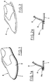
- Figures 1 and 1a show the IDEAL method, according to which the insole 1 is joined, by a peripheral seam 2, to the edge 3a of an upper 3, so that the border of the edge 3a is flush with the insole 1 along the whole outline of the latter.
- Figures 2 and 2a show the first step of the S. CRISPINO method, according to which the insole 1 is joined to the edge 3a of the upper by means of a peripheral seam 2.
- the border of the edge 3a protrudes from the outline of the insole 1 by a predetermined value, which is maintained more or less constant along the whole periphery.
- edge 3a is folded and glued to the lower surface of the insole 1, so as to cover the seam line 2.
- the traditional way of joining the upper and the insole according to the above described methods includes a pre-assembling operation, which is carried out before the stitching and during which the upper edge is glued to the insole in the joining area.
- the pre-assembling operation requires the use of some lasts, includes several subsequent steps and necessitates machines prepared for this specific purpose, and is performed in the following order:
- the upper-insole assembly is stitched by the machines of the type "Rapida” or “Blake”, known in the footwear field.
- the upper is joined to the insole without using the lasts or any preliminary operations, such as edges previous gluing and pressing, but by stitching directly the edges by a special machine.
- This special machine includes a guide, which has vertical surfaces, on which the edges being stitched are held in suitable positions and are fed, while a needle is moved in a plane crosswise to the edges.
- the upper and the insole are equipped, along their edges, with a series of reference marks which must coincide with one another when the seam is completed, so as to verify the correct reciprocal positioning.
- the apparatus is equipped with a wrinkling group, situated beside the guide and aimed at acting on the upper, so as to make wrinkles along its edge, thus making the longer peripheral extension of the upper match with the insole outline.
- This method and apparatus are prepared explicitly for joining an upper to an insole obtained by the above described S. CRISPINO method.
- the object of the present invention is to propose a machine, which uses the teachings of the above described method and can stitch an upper to an insole obtained by the IDEAL or S. CRISPINO method, by a simple substitution of some elements.
- Another object of the present invention is to propose a machine, whose guiding means for the edges to be stitched are shaped in such a way, as to assure the stitching high quality and, at the same time, to make it easy for an operator to handle the upper and insole during the whole stitching process.
- a further object of the present invention is to propose a machine, which can use medium and thick thread and which can perform knotted stitch.
- the proposed machine is aimed at performing a peripheral seam 2, which joins firmly an insole 1 with an upper 3 of an open type.
- peripheral seam 2 allows to obtain a insole-upper assembly, according to the IDEAL or S. CRISPINO methods, described in the introductory statement with reference to Figures 1, 1a and 2.
- the seam shown in Figures 2 and 2a is the first step of S. CRISPINO method, according to which in a second step ( Figures 3 and 3a), the upper edge is folded and glued to the lower surface of the insole, so as to cover the seam line.
- the second step is performed with known machines, which are not part of the present invention; the step is described only to complete the information about the S. CRISPINO method.
- the proposed machine is obtained using a structure and associated means analogous to the ones described in the US Patent No. 4.848.252 granted to the Applicant.
- the machine includes a head, which supports, among other elements, a longitudinal shaft equipped with a transversal arm 6.
- the needle 7 is operated on a plane transversal to a longitudinal guide 10, which supports and guides the edges to be stitched.
- the needle 7 is made oscillate between an idle position, beside the guide 10, and a stitching position, in which the needle passes through a slot made in the guide 10, so as to pierce the edges to be stitched.
- the shaft of the needle 7 reciprocates axially by strokes of predetermined step, in step relation with oscillation of the needle.
- the threads of the needle 7 and the crochet 8 bobbin can be of either medium or thick type.
- the crochet 8 is situated beside the guide 10, on the side opposite to the one where the needle enters the slot, and is made translate axially, synchronously with the shaft of the needle 7.
- a wrinkling group 60 also situated on the side where the needle 7 enters the slot, is operated to move alternately, in a direction longitudinal with respect to the guide 10 and crosswise thereto, in a suitable step relation with the guide 10 movement and with the needle 7 oscillation.
- the wrinkling group 60 carries a small head 66, which acts on the edge to be stitched situated directly below it (shoe upper), so as to accelerate the movement thereof with respect to the other edge, thus wrinkling the edge in the stitching parts, where it is required, e.g. in the region of the shoe toe.
- the guide 10 includes a main body 30, depending from a support 20, integral with the head of the proposed machine.
- the lower part of the main body 30 is so shaped as to form a vertical support surface 33, situated on the side where the needle 7 enters the slot, with a slot 37, open from the side toward the head, which allows the needle 7 passage and the translation thereof together with the stitched edges.
- Stop means 40 situated beside the support surface 33 and on the side where the needle 7 enters the slot, are fastened to the main body 30 in an adjustable position.
- edges of the upper 3 and the insole 1 go in abutment against the stop means 40, which define also a side stop for the edge 3a of the upper 3.
- the stop means 40 cooperate with the support surface 33, so as to guide the edges of the upper 3 and the insole 1 in the region of the needle 7 transition.
- the stop means 40 are formed by a prong 41, removably fastened, by a screw 42, in a first seat 31 made in the main body 30.
- the height of the prong 41 is adjustable with respect to the main body 30 by the slotted hole 43, through which the screw 42 passes and whose lower horizontal surface 44 defines a common abutment for the insole 1 and the upper 3.
- the adjustment of the prong 41 height allows to change the distance between the borders of the edges and the seam line being realized.
- the prong 41 is equipped also with a tooth 45, situated in the region of its end facing the edges to be stitched, while being introduced.
- the tooth 45 extends downwards with respect to horizontal surface 44, so as to support laterally the edge 3a of the upper 3 by maintaining it close to the corresponding edge of the insole 1.
- the stop means 40 are formed by a pair of feet 51, 52, removably fastened, by relative screws 53, 54, respectively in a first seat 31 of the main body 30 and in a second seat 32, situated beside the first one.
- the first foot 51 forms a horizontal strip 51a, against which the upper part of the insole 1 goes in abutment.
- the second foot 52 includes a horizontal strip 52a, which extends laterally downwards, so as to form a substantially vertical wall 52b.
- the upper part of the upper 3 edge goes in abutment against the wall 52b and is supported laterally thereby.
- the feet 51, 52 are adjustable in height, with respect to the main body 30, independently one from the other, by slots made in the through holes of the fastening screws, so as to obtain the desired protrusion of the edge 3a of the upper 3 with respect to the insole 1 and the desired position of the seam line, as has been already described for the prong 41.
- a separating baffle 70 hinged to the main body 30 by a pivot 71, cooperates with the wrinkling group 60 in step relation therewith.
- the separating baffle 70 has a semi-lunar shape and is joined, by a connecting rod 72, to an actuator 73, e.g. pneumatic, which makes the separating baffle 70 oscillate on a plane parallel to the support surface 33, between two positions, rest position "I” and working position "O", respectively.
- an actuator 73 e.g. pneumatic
- the separating baffle 70 is introduced between the edges of the upper and the insole in the part corresponding to the working area of the head 66 of the wrinkling group 60.
- the separating baffle 70 is aimed at limiting the action of the head 66 to the edge 3a of the upper 3, thus avoiding undesired translation of the edge of the insole 1 that could be provoked, due to friction, by the wrinkling of the upper 3 edge.
- the operator introduces the edges of the upper and of the insole in the respective positions, i.e. the upper arranged on the side where the needle 7 enters the slot and the insole lying on the support surface 33 of the main body 30, making sure that the edges go in abutment against respective upper stops and that the reference signs 4, 5 pre-established as the stitching beginning are aligned with the needle 7 transition point.
- the machine is started and the operator follows the edges to be stitched introduced into the guide 10 until the peripheral seam 2 is completed.
- the operator operates the wrinkling group 60, e.g. during the toe stitching; this operation is synchronized with the command of the actuator 73 to bring the separating baffle 70 to the working position "O".
- the described machine can perform stitch an upper 3 to an insole 1 according to IDEAL or S. CRISPINO method, with only one operation and without using lasts or gluing.
- the proposed machine allows to change radically the production techniques used so far, allowing to produce, with reasonable cost, shoes which were very expensive before.
- the above described curved needle 7 can be substituted by a straight needle operated horizontally.
- the proposed structure of the machine which can use medium and thick thread and which can perform knotted stitch, allows to obtain a upper-insole assembly, which is very strong and impermeable.
- the obtained seam is very nice and regular, thus it can form an ornament of the shoe, leaving a large choice of the bottom type to be joined the unit upper-insole.
Landscapes
- Engineering & Computer Science (AREA)
- Textile Engineering (AREA)
- Footwear And Its Accessory, Manufacturing Method And Apparatuses (AREA)
- Sewing Machines And Sewing (AREA)
Abstract
Description
- The present invention relates to machines for stitching footwear.
- As it is known, there are different types of footwear manufacture with well defined technical and aesthetic characteristics.
- In two of these types, the so-called IDEAL and S. CRISPINO, the upper is open and firmly joined to a related insole made of a semi-rigid material, so as to obtain a unit, which is then joined with a sole made of leather, gum or the like.
- Figures 1 and 1a show the IDEAL method, according to which the
insole 1 is joined, by aperipheral seam 2, to theedge 3a of an upper 3, so that the border of theedge 3a is flush with theinsole 1 along the whole outline of the latter. - Figures 2 and 2a show the first step of the S. CRISPINO method, according to which the
insole 1 is joined to theedge 3a of the upper by means of aperipheral seam 2. - In this case, the border of the
edge 3a protrudes from the outline of theinsole 1 by a predetermined value, which is maintained more or less constant along the whole periphery. - During a second step (Figures 3 and 3a), the
edge 3a is folded and glued to the lower surface of theinsole 1, so as to cover theseam line 2. - The traditional way of joining the upper and the insole according to the above described methods, includes a pre-assembling operation, which is carried out before the stitching and during which the upper edge is glued to the insole in the joining area.
- The pre-assembling operation requires the use of some lasts, includes several subsequent steps and necessitates machines prepared for this specific purpose, and is performed in the following order:
- application of glue to the upper and the insole, which glue can be reactivated later on;
- mounting the upper on the last and positioning of the insole;
- gluing the toe area by a first machine;
- gluing the hill area by a second machine;
- gluing the sides by a third machine;
- pressing the glued edge and possible trimming of the exceeding material (IDEAL method), so that it is flush with the in sole (so-called "wheeling step").
- After the above steps have been completed, the upper-insole assembly is stitched by the machines of the type "Rapida" or "Blake", known in the footwear field.
- It is quite evident from what above that such a procedure is so slow, difficult and expensive, that the above described IDEAL and S.CRISPINO methods cannot be performed but for very valuable and expensive shoes.
- Another disadvantage of the above described methods derives from the fact that the above described techniques require highly specialized operators, with all the inconveniences caused thereby.
- In order to avoid the above disadvantages, the Applicant filed a Patent Application No. BO97A 000552 on 10/09/1997, which discloses a "Method and apparatus for stitching footwear upper to a related insole".
- According to this method, the upper is joined to the insole without using the lasts or any preliminary operations, such as edges previous gluing and pressing, but by stitching directly the edges by a special machine. This special machine includes a guide, which has vertical surfaces, on which the edges being stitched are held in suitable positions and are fed, while a needle is moved in a plane crosswise to the edges.
- According to this method, the upper and the insole are equipped, along their edges, with a series of reference marks which must coincide with one another when the seam is completed, so as to verify the correct reciprocal positioning.
- The apparatus is equipped with a wrinkling group, situated beside the guide and aimed at acting on the upper, so as to make wrinkles along its edge, thus making the longer peripheral extension of the upper match with the insole outline.
- This method and apparatus are prepared explicitly for joining an upper to an insole obtained by the above described S. CRISPINO method.
- The object of the present invention is to propose a machine, which uses the teachings of the above described method and can stitch an upper to an insole obtained by the IDEAL or S. CRISPINO method, by a simple substitution of some elements.
- Another object of the present invention is to propose a machine, whose guiding means for the edges to be stitched are shaped in such a way, as to assure the stitching high quality and, at the same time, to make it easy for an operator to handle the upper and insole during the whole stitching process.
- A further object of the present invention is to propose a machine, which can use medium and thick thread and which can perform knotted stitch.
- The characteristic features of the proposed machine will be pointed out in the following description with reference to the enclosed drawings, in which:
- Figure 1 shows an upper joined to an insole according to the IDEAL method;
- Figure 1a shows an enlarged partially section view of the joining area of the upper and insole of Figure 1;
- Figure 2 shows an upper joined to an insole, in a first step of S. CRISPINO method;
- Figure 2a shows an enlarged partially section view of the joining area of the upper and insole of Figure 2;
- Figure 3 shows a second step of S. CRISPINO method;
- Figure 3a shows an enlarged partially section view of the joining area of the upper and insole of Figure 3;
- Figure 4 shows an exploded view of a shoe upper and an insole ready to be stitched by the proposed machine;
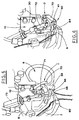
- Figures 5 and 6 show two working positions of the proposed machine stitching means, according to the IDEAL method;
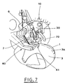
- Figure 7 shows stitching of an upper to an insole according to a technique shown in Figures 1 and 1a;
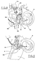
- Figure 8 shows the proposed machine stitching means, when they are set according to the S. CRISPINO method;
- Figure 9 shows stitching of an upper to an insole according to a technique shown in Figures 2 and 2a;
- Figure 10 shows an exploded perspective view of the elements forming the guide.
- The proposed machine is aimed at performing a
peripheral seam 2, which joins firmly aninsole 1 with an upper 3 of an open type. - The above mentioned
peripheral seam 2 allows to obtain a insole-upper assembly, according to the IDEAL or S. CRISPINO methods, described in the introductory statement with reference to Figures 1, 1a and 2. - As it has been already stated, the seam shown in Figures 2 and 2a is the first step of S. CRISPINO method, according to which in a second step (Figures 3 and 3a), the upper edge is folded and glued to the lower surface of the insole, so as to cover the seam line.
- The second step is performed with known machines, which are not part of the present invention; the step is described only to complete the information about the S. CRISPINO method.
- Before being stitched together by the proposed machine, the
insole 1 and the upper 3 are marked along their edges with a series ofreference signs 4, 5 which must match after the seam has been completed (Figure 4). - According to a preferred, but not only embodiment, the proposed machine is obtained using a structure and associated means analogous to the ones described in the US Patent No. 4.848.252 granted to the Applicant.
- The machine includes a head, which supports, among other elements, a longitudinal shaft equipped with a
transversal arm 6. - A
needle 7, extending along a circumferential arc, if fastened tangentially to one end of thetransversal arm 6, coaxial with the shaft. - The
needle 7 is operated on a plane transversal to alongitudinal guide 10, which supports and guides the edges to be stitched. - The
needle 7 is made oscillate between an idle position, beside theguide 10, and a stitching position, in which the needle passes through a slot made in theguide 10, so as to pierce the edges to be stitched. - The shaft of the
needle 7 reciprocates axially by strokes of predetermined step, in step relation with oscillation of the needle. - A
crochet 8, equipped with a bobbin of stitching thread, cooperates with theneedle 7, so as to perform a knotted stitch. - It is to be pointed out that the threads of the
needle 7 and thecrochet 8 bobbin can be of either medium or thick type. - The
crochet 8 is situated beside theguide 10, on the side opposite to the one where the needle enters the slot, and is made translate axially, synchronously with the shaft of theneedle 7. - A
leather presser 9, situated on the side where theneedle 7 enters the slot, moves transversely to theguide 10, in a suitable step relation with theneedle 7 oscillation, so as to block the leather edges when the needle is being withdrawn. - A
wrinkling group 60, also situated on the side where theneedle 7 enters the slot, is operated to move alternately, in a direction longitudinal with respect to theguide 10 and crosswise thereto, in a suitable step relation with theguide 10 movement and with theneedle 7 oscillation. - The
wrinkling group 60 carries asmall head 66, which acts on the edge to be stitched situated directly below it (shoe upper), so as to accelerate the movement thereof with respect to the other edge, thus wrinkling the edge in the stitching parts, where it is required, e.g. in the region of the shoe toe. - According to the machine obtained by the present invention, the
guide 10 includes amain body 30, depending from asupport 20, integral with the head of the proposed machine. - The lower part of the
main body 30 is so shaped as to form avertical support surface 33, situated on the side where theneedle 7 enters the slot, with aslot 37, open from the side toward the head, which allows theneedle 7 passage and the translation thereof together with the stitched edges. - The lower surface of the
insole 1, arranged vertically together with theedge 3a of the upper 3, lies on thesupport surface 33, as will be explained later on. - Stop means 40, situated beside the
support surface 33 and on the side where theneedle 7 enters the slot, are fastened to themain body 30 in an adjustable position. - The edges of the upper 3 and the
insole 1 go in abutment against the stop means 40, which define also a side stop for theedge 3a of the upper 3. - The stop means 40 cooperate with the
support surface 33, so as to guide the edges of the upper 3 and theinsole 1 in the region of theneedle 7 transition. - According to a first embodiment, for stitching the upper and the insole with the IDEAL method, the stop means 40 are formed by a
prong 41, removably fastened, by ascrew 42, in afirst seat 31 made in themain body 30. - The height of the
prong 41 is adjustable with respect to themain body 30 by the slottedhole 43, through which thescrew 42 passes and whose lowerhorizontal surface 44 defines a common abutment for theinsole 1 and the upper 3. - The adjustment of the
prong 41 height allows to change the distance between the borders of the edges and the seam line being realized. - The
prong 41 is equipped also with atooth 45, situated in the region of its end facing the edges to be stitched, while being introduced. Thetooth 45 extends downwards with respect tohorizontal surface 44, so as to support laterally theedge 3a of the upper 3 by maintaining it close to the corresponding edge of theinsole 1. - According to another embodiment, for stitching the upper and the insole with the S. CRISPINO method, the stop means 40 are formed by a pair of
feet relative screws first seat 31 of themain body 30 and in asecond seat 32, situated beside the first one. - The
first foot 51 forms ahorizontal strip 51a, against which the upper part of theinsole 1 goes in abutment. - The
second foot 52 includes ahorizontal strip 52a, which extends laterally downwards, so as to form a substantiallyvertical wall 52b. - The upper part of the upper 3 edge goes in abutment against the
wall 52b and is supported laterally thereby. - The
feet main body 30, independently one from the other, by slots made in the through holes of the fastening screws, so as to obtain the desired protrusion of theedge 3a of the upper 3 with respect to theinsole 1 and the desired position of the seam line, as has been already described for theprong 41. - A separating
baffle 70, hinged to themain body 30 by apivot 71, cooperates with thewrinkling group 60 in step relation therewith. - The separating
baffle 70 has a semi-lunar shape and is joined, by a connectingrod 72, to anactuator 73, e.g. pneumatic, which makes the separatingbaffle 70 oscillate on a plane parallel to thesupport surface 33, between two positions, rest position "I" and working position "O", respectively. - When in the working position "O", the separating
baffle 70 is introduced between the edges of the upper and the insole in the part corresponding to the working area of thehead 66 of thewrinkling group 60. - The separating
baffle 70 is aimed at limiting the action of thehead 66 to theedge 3a of the upper 3, thus avoiding undesired translation of the edge of theinsole 1 that could be provoked, due to friction, by the wrinkling of the upper 3 edge. - In order to stitch, it is necessary to prepare the machine in a suitable way, mounting and adjusting correctly the
prong 41 for the IDEAL method orfeet - Then, the operator introduces the edges of the upper and of the insole in the respective positions, i.e. the upper arranged on the side where the
needle 7 enters the slot and the insole lying on thesupport surface 33 of themain body 30, making sure that the edges go in abutment against respective upper stops and that thereference signs 4, 5 pre-established as the stitching beginning are aligned with theneedle 7 transition point. - Afterwards, the machine is started and the operator follows the edges to be stitched introduced into the
guide 10 until theperipheral seam 2 is completed. - The operator operates the
wrinkling group 60, e.g. during the toe stitching; this operation is synchronized with the command of theactuator 73 to bring the separatingbaffle 70 to the working position "O". - Therefore, the described machine can perform stitch an upper 3 to an
insole 1 according to IDEAL or S. CRISPINO method, with only one operation and without using lasts or gluing. - The evident advantages of the proposed machine derive from the simplification with respect to the traditional systems, which results in enormous saving of time, less equipment and machines.
- It is to be noted that the proposed machine use is extremely easy, thus it can be operated even by not highly specialized operators, which allows to keep the production costs low.
- Consequently, the proposed machine allows to change radically the production techniques used so far, allowing to produce, with reasonable cost, shoes which were very expensive before.
- The above described
curved needle 7 can be substituted by a straight needle operated horizontally. - The proposed structure of the machine, which can use medium and thick thread and which can perform knotted stitch, allows to obtain a upper-insole assembly, which is very strong and impermeable.
- Moreover, the obtained seam is very nice and regular, thus it can form an ornament of the shoe, leaving a large choice of the bottom type to be joined the unit upper-insole.
Claims (6)
- Machine for stitching an upper to a relative insole, said machine including:a longitudinal guide (10) joined to the machine head;a needle (7), operated in a plane transversal to said guide (10) between an idle position, on a side of the guide (10) facing said upper (3), and a stitching position, in which the needle passes first through the edge of the upper (3) and then through the edge of the insole, said needle (7) being reciprocated, parallel to said guide (10), with strokes of a predetermined step;a crochet (8), with a bobbin, of stitching thread, situated beside said guide (10) on the side opposite to the side where the needle (7) enters said upper, said crochet (8) aimed at cooperating with said needle to make a seam;a wrinkling group (60), situated beside said guide (10) and equipped with a head (66), which is operated in alternate movement, crosswise to said guide (10), so as to engage the edge (3a) of the upper (3), and longitudinally to said guide (10), so as to wrinkle said edge (3a) of the upper (3), said machine being characterized in that said guide (10) includes :a main body (30) integral with the machine head, with the lower part of said main body (30) forming a vertical support surface (33), arranged on a side where the needle (7) enters said upper, and acting as support against which the lower surface of said insole (1) goes in abutment;stop means (40) fastened in an adjustable position to said main body (30) and acting as an upper abutment for said upper (3) and insole (1), as well as a lateral guide of said edge (3a) of the upper (3), said stop means (40) cooperating with said support surface (33) in guiding the edges, arranged one close to the other, at the needle (7) transition point;a separating baffle (70), hinged to said main body (30) and joined to an actuator (73), which operates it to oscillate between two positions, rest position (I) and working position (O), respectively, with said working position (O) being defined in step relation with the operation of said wrinkling group (60), with said separating baffle (70), while in said working position, being introduced between the edges of said upper (3) and insole (1) in the part corresponding to the working area of said head (66).
- Machine, according to claim 1, characterized in that said stop means (40), when used according to a technique, in which the ends of the upper and insole edges are aligned, are formed by a prong (41) removably fastened, by a screw (42), in a first seat (31) made in said main body (30), said prong (41) being adjustable in height and defining, with its lower horizontal surface (44) a common abutment for said edges.
- Machine, according to claim 2, characterized in that said prong (41) is equipped with a tooth (45), situated at its end facing the edges to be stitched while being introduced, said tooth (45) extending downwards with respect to horizontal surface (44), so as to support laterally said edge (3a) of the upper (3).
- Machine, according to claim 1, characterized in that said stop means (40), when used according to a technique, in which the edge (3a) of the upper (3) protrudes with respect to the edge of the insole (1), are formed by a pair of teeth (51,52), first and second, respectively, removably fastened, by relative screws (53,54), in corresponding first and second seats (31,32) made in said main body (30), with said feet (51,52) being adjustable in height independently one from the other, and including relative horizontal strips (51a,52a), which act as the abutments for the upper part of the insole (1) and said edge (3a) of the upper (3), respectively.
- Machine, according to claim 4, characterized in that said second foot (52) includes a substantially vertical wall (52b), which extends laterally downwards of the relative horizontal strip (52a), so as to support laterally the edge (3a) of said upper (3).
- Machine, according to claim 1, characterized in that said longitudinal guide (10) allows to realize a knotted stitching with two threads, either of medium or thick type, carried respectively by said needle (7) and said bobbin joined to the crochet (8).
Applications Claiming Priority (2)
| Application Number | Priority Date | Filing Date | Title |
|---|---|---|---|
| IT1999BO000399A IT1310413B1 (en) | 1999-07-16 | 1999-07-16 | MACHINE FOR THE SEWING OF A UPPER TO A RELATIVE FOOTBED INSOLE. |
| ITBO990399 | 1999-07-16 |
Publications (3)
| Publication Number | Publication Date |
|---|---|
| EP1069225A2 true EP1069225A2 (en) | 2001-01-17 |
| EP1069225A3 EP1069225A3 (en) | 2002-03-20 |
| EP1069225B1 EP1069225B1 (en) | 2005-03-02 |
Family
ID=11344128
Family Applications (1)
| Application Number | Title | Priority Date | Filing Date |
|---|---|---|---|
| EP00114160A Expired - Lifetime EP1069225B1 (en) | 1999-07-16 | 2000-07-12 | Machine for stitching a shoe upper to an insole |
Country Status (5)
| Country | Link |
|---|---|
| EP (1) | EP1069225B1 (en) |
| CN (1) | CN1131904C (en) |
| BR (1) | BR0002734A (en) |
| IT (1) | IT1310413B1 (en) |
| TW (1) | TW509236U (en) |
Cited By (1)
| Publication number | Priority date | Publication date | Assignee | Title |
|---|---|---|---|---|
| CN117587584A (en) * | 2023-12-07 | 2024-02-23 | 上工富怡智能制造(天津)有限公司 | Slippers production line and production method |
Families Citing this family (1)
| Publication number | Priority date | Publication date | Assignee | Title |
|---|---|---|---|---|
| IT1396131B1 (en) | 2009-10-13 | 2012-11-16 | Eredi Di Ciucani Mocassino Machinery Di Ciucani Mario | SYSTEM FOR THE SUPPORT AND ORIENTATION OF A SEWING MACHINE WITH CURVED NEEDLE. |
Citations (2)
| Publication number | Priority date | Publication date | Assignee | Title |
|---|---|---|---|---|
| US4848252A (en) | 1986-05-07 | 1989-07-18 | Mario Ciucani | Automatic machine for sewing different kinds of articles, especially articles made of leather |
| ITBO970552A1 (en) | 1997-09-10 | 1999-03-10 | Mario Ciucani | METHOD AND EQUIPMENT FOR SEWING FOOTWEAR TO AN INSOLE. |
Family Cites Families (1)
| Publication number | Priority date | Publication date | Assignee | Title |
|---|---|---|---|---|
| IT1280003B1 (en) * | 1995-08-01 | 1997-12-23 | Mario Ciucani | METHOD FOR SEWING VARIOUS ITEMS, IN PARTICULAR LEATHER ITEMS, AND MACHINE FOR IMPLEMENTING THIS METHOD. |
-
1999
- 1999-07-16 IT IT1999BO000399A patent/IT1310413B1/en active
-
2000
- 2000-07-12 EP EP00114160A patent/EP1069225B1/en not_active Expired - Lifetime
- 2000-07-12 TW TW090215062U patent/TW509236U/en not_active IP Right Cessation
- 2000-07-13 BR BR0002734-0A patent/BR0002734A/en not_active IP Right Cessation
- 2000-07-14 CN CN00120247.2A patent/CN1131904C/en not_active Expired - Fee Related
Patent Citations (2)
| Publication number | Priority date | Publication date | Assignee | Title |
|---|---|---|---|---|
| US4848252A (en) | 1986-05-07 | 1989-07-18 | Mario Ciucani | Automatic machine for sewing different kinds of articles, especially articles made of leather |
| ITBO970552A1 (en) | 1997-09-10 | 1999-03-10 | Mario Ciucani | METHOD AND EQUIPMENT FOR SEWING FOOTWEAR TO AN INSOLE. |
Cited By (1)
| Publication number | Priority date | Publication date | Assignee | Title |
|---|---|---|---|---|
| CN117587584A (en) * | 2023-12-07 | 2024-02-23 | 上工富怡智能制造(天津)有限公司 | Slippers production line and production method |
Also Published As
| Publication number | Publication date |
|---|---|
| EP1069225A3 (en) | 2002-03-20 |
| TW509236U (en) | 2002-11-01 |
| CN1131904C (en) | 2003-12-24 |
| IT1310413B1 (en) | 2002-02-13 |
| ITBO990399A1 (en) | 2001-01-16 |
| BR0002734A (en) | 2001-03-13 |
| EP1069225B1 (en) | 2005-03-02 |
| ITBO990399A0 (en) | 1999-07-16 |
| CN1282553A (en) | 2001-02-07 |
Similar Documents
| Publication | Publication Date | Title |
|---|---|---|
| US4274345A (en) | Machine for sewing together workpiece parts having edges of equal or unequal length by means of a bead seam | |
| US5964171A (en) | Method for sewing various kinds of articles, in particular made of leather, and machine for carrying out this method | |
| EP2497384B1 (en) | A method and a sewing machine for realising a semi-finished workpiece to be used in constructing a shoe. | |
| EP1069225B1 (en) | Machine for stitching a shoe upper to an insole | |
| US3282234A (en) | Sewing machine including work folding means | |
| JP2002085873A (en) | Presser bar for sewing machine | |
| US1630754A (en) | Method and apparatus for embossing flexible material | |
| US4364318A (en) | Machine for sewing together workpiece parts having edges of equal or unequal length by means of a bead seam | |
| KR100395709B1 (en) | A device for sewing two items, such as leather parts, with overlapping ends | |
| US2684494A (en) | Method of making stitchdown shoes | |
| US4829921A (en) | Presser foot for a sewing machine including a fulling rod and a trimming knife slot | |
| US2222972A (en) | Shoe sewing machine | |
| US2684648A (en) | Machine for sewing shoes | |
| US319740A (en) | Method of forming insoles for shoes | |
| US2359803A (en) | Sewing machine | |
| WO1997032070A1 (en) | Automatic sewing machine for various articles, in particular leather articles | |
| US2192166A (en) | Shoe sewing machine | |
| US2190355A (en) | Shoe sewing machine | |
| US1118883A (en) | Outsole trimming and channeling machine. | |
| US2064417A (en) | Method of making turned footwear | |
| US2036406A (en) | Method of making shoes | |
| US579922A (en) | c oupal | |
| US3081720A (en) | Folding and feeding attachments for sewing machines | |
| WO2003056965A1 (en) | A device for folding and contemporary gluing of a shoe upper edge to an insole | |
| US2249811A (en) | Machine for applying edge-binding strips |
Legal Events
| Date | Code | Title | Description |
|---|---|---|---|
| PUAI | Public reference made under article 153(3) epc to a published international application that has entered the european phase |
Free format text: ORIGINAL CODE: 0009012 |
|
| AK | Designated contracting states |
Kind code of ref document: A2 Designated state(s): AT BE CH CY DE DK ES FI FR GB GR IE IT LI LU MC NL PT SE Kind code of ref document: A2 Designated state(s): ES |
|
| AX | Request for extension of the european patent |
Free format text: AL;LT;LV;MK;RO;SI |
|
| PUAL | Search report despatched |
Free format text: ORIGINAL CODE: 0009013 |
|
| AK | Designated contracting states |
Kind code of ref document: A3 Designated state(s): AT BE CH CY DE DK ES FI FR GB GR IE IT LI LU MC NL PT SE |
|
| AX | Request for extension of the european patent |
Free format text: AL;LT;LV;MK;RO;SI |
|
| 17P | Request for examination filed |
Effective date: 20020912 |
|
| AKX | Designation fees paid |
Free format text: ES |
|
| AXX | Extension fees paid |
Free format text: RO PAYMENT 20020912 |
|
| REG | Reference to a national code |
Ref country code: DE Ref legal event code: 8566 |
|
| GRAP | Despatch of communication of intention to grant a patent |
Free format text: ORIGINAL CODE: EPIDOSNIGR1 |
|
| GRAS | Grant fee paid |
Free format text: ORIGINAL CODE: EPIDOSNIGR3 |
|
| GRAA | (expected) grant |
Free format text: ORIGINAL CODE: 0009210 |
|
| AK | Designated contracting states |
Kind code of ref document: B1 Designated state(s): ES |
|
| AX | Request for extension of the european patent |
Extension state: RO |
|
| PG25 | Lapsed in a contracting state [announced via postgrant information from national office to epo] |
Ref country code: ES Free format text: LAPSE BECAUSE OF FAILURE TO SUBMIT A TRANSLATION OF THE DESCRIPTION OR TO PAY THE FEE WITHIN THE PRESCRIBED TIME-LIMIT Effective date: 20050302 |
|
| REG | Reference to a national code |
Ref country code: IE Ref legal event code: FG4D |
|
| PLBE | No opposition filed within time limit |
Free format text: ORIGINAL CODE: 0009261 |
|
| STAA | Information on the status of an ep patent application or granted ep patent |
Free format text: STATUS: NO OPPOSITION FILED WITHIN TIME LIMIT |
|
| 26N | No opposition filed |
Effective date: 20051205 |