EP1069062A2 - Device for monitoring the transport of flat signatures - Google Patents
Device for monitoring the transport of flat signatures Download PDFInfo
- Publication number
- EP1069062A2 EP1069062A2 EP00114164A EP00114164A EP1069062A2 EP 1069062 A2 EP1069062 A2 EP 1069062A2 EP 00114164 A EP00114164 A EP 00114164A EP 00114164 A EP00114164 A EP 00114164A EP 1069062 A2 EP1069062 A2 EP 1069062A2
- Authority
- EP
- European Patent Office
- Prior art keywords
- folder
- copies
- sensors
- folding
- sensor
- Prior art date
- Legal status (The legal status is an assumption and is not a legal conclusion. Google has not performed a legal analysis and makes no representation as to the accuracy of the status listed.)
- Granted
Links
- 238000012544 monitoring process Methods 0.000 title claims abstract description 25
- 238000000034 method Methods 0.000 claims abstract description 20
- 238000010200 validation analysis Methods 0.000 claims description 15
- 239000000463 material Substances 0.000 claims description 11
- 238000011156 evaluation Methods 0.000 claims description 2
- 238000012545 processing Methods 0.000 claims description 2
- 238000001514 detection method Methods 0.000 description 10
- 230000004913 activation Effects 0.000 description 4
- 230000003287 optical effect Effects 0.000 description 4
- 230000001419 dependent effect Effects 0.000 description 2
- 238000010586 diagram Methods 0.000 description 2
- 230000015572 biosynthetic process Effects 0.000 description 1
- 238000004364 calculation method Methods 0.000 description 1
- 230000001934 delay Effects 0.000 description 1
- 230000006870 function Effects 0.000 description 1
- 230000007257 malfunction Effects 0.000 description 1
- 230000005693 optoelectronics Effects 0.000 description 1
- 238000004806 packaging method and process Methods 0.000 description 1
- 239000000758 substrate Substances 0.000 description 1
- 238000012360 testing method Methods 0.000 description 1
- 230000001960 triggered effect Effects 0.000 description 1
- 238000011144 upstream manufacturing Methods 0.000 description 1
Images


Classifications
-
- B—PERFORMING OPERATIONS; TRANSPORTING
- B65—CONVEYING; PACKING; STORING; HANDLING THIN OR FILAMENTARY MATERIAL
- B65H—HANDLING THIN OR FILAMENTARY MATERIAL, e.g. SHEETS, WEBS, CABLES
- B65H43/00—Use of control, checking, or safety devices, e.g. automatic devices comprising an element for sensing a variable
- B65H43/02—Use of control, checking, or safety devices, e.g. automatic devices comprising an element for sensing a variable detecting, or responding to, absence of articles
-
- B—PERFORMING OPERATIONS; TRANSPORTING
- B65—CONVEYING; PACKING; STORING; HANDLING THIN OR FILAMENTARY MATERIAL
- B65H—HANDLING THIN OR FILAMENTARY MATERIAL, e.g. SHEETS, WEBS, CABLES
- B65H2511/00—Dimensions; Position; Numbers; Identification; Occurrences
- B65H2511/30—Numbers, e.g. of windings or rotations
-
- B—PERFORMING OPERATIONS; TRANSPORTING
- B65—CONVEYING; PACKING; STORING; HANDLING THIN OR FILAMENTARY MATERIAL
- B65H—HANDLING THIN OR FILAMENTARY MATERIAL, e.g. SHEETS, WEBS, CABLES
- B65H2511/00—Dimensions; Position; Numbers; Identification; Occurrences
- B65H2511/50—Occurence
- B65H2511/51—Presence
-
- B—PERFORMING OPERATIONS; TRANSPORTING
- B65—CONVEYING; PACKING; STORING; HANDLING THIN OR FILAMENTARY MATERIAL
- B65H—HANDLING THIN OR FILAMENTARY MATERIAL, e.g. SHEETS, WEBS, CABLES
- B65H2513/00—Dynamic entities; Timing aspects
- B65H2513/40—Movement
-
- B—PERFORMING OPERATIONS; TRANSPORTING
- B65—CONVEYING; PACKING; STORING; HANDLING THIN OR FILAMENTARY MATERIAL
- B65H—HANDLING THIN OR FILAMENTARY MATERIAL, e.g. SHEETS, WEBS, CABLES
- B65H2513/00—Dynamic entities; Timing aspects
- B65H2513/50—Timing
- B65H2513/512—Starting; Stopping
Definitions
- the invention relates to a device for monitoring the transport flat copies, for example in a folder from a material web severed and there to be folded longitudinally and / or transversely.
- EP 0847 857 A1 relates to an adjustment device in front of a cylinder a traverse arranged in a rotary printing machine. There is one on the traverse Measuring device can be moved axially to the lateral surface of the cylinder by means of a holder.
- the adjustment aid has a light beam on the cylinder projecting optical element and at least one optical receiver, which is a reflected from the cylinder Beam of light receives.
- the optical receiver comprises an optoelectronic one Sensor that is used in conjunction with evaluation electronics to record the Position of the reflected light beam on the sensor is suitable.
- This device is primarily used to align the surface of the cylinder scanning optical measuring device.
- EP 0753 409 relates to a sheet-fed printing machine with a delivery the top of which should be continuously fed sheets.
- a traversing measuring device one attached to the leading edge of the sheets To scan pressure control strips. For this purpose, they can be moved on a traverse Measuring device associated with sheet retainers, which prevent the during the execution of a measuring process promoted sheet on the top of the stack.
- US 3,815,895 discloses a paper jam detection system for folders, one of which Role rotation are subordinate.
- Locating photocells detect both absent and incorrectly also incorrectly existing copies along the conveyor path through the Folders.
- a timing control unit that works synchronously with the folder, generates signals that trigger a detection of whether one is on a particular The place where the expected copy actually exists is there and whether it is on a specific one Unexpected copy of the conveyor path at this point actually does not arrive.
- the signals from the photocells will match those the timing control unit logically linked, supplied to a logic circuit, the stops the folder if necessary.
- the system also detects when in the paper jam detection system one of the photocells has failed.
- the invention is based on the object To provide paper flow monitoring system, which at slow paper feed speeds responds to irregularities in specimen transport.
- the limit values that enable validation are on the monitoring unit can be specified and stored there so that it is always up to date for the necessary calculations be available.
- the difference is in the monitoring unit according to the present method of the number of copies detected per validated sensor and from the folder number of copies located is determined continuously, with a maximum permissible Difference can be specified on the monitoring unit. This can be dependent from the substrate parameters, copy thickness and empirical values to set the monitoring system according to the order.
- the sensors required to carry out the method according to the invention it is preferably sensor pairs consisting of a transmit and a Receiving part exist. These are spaced from each other, being between transmit and the receiving section of the specimen conveyor path.
- the cutting cylinder or the drive assigned to the folder can be used as a proximity switch or encoders such as rotary encoders, for example, are configured per revolution a pulse to the monitoring unit of the unit concerned submit, which is summed up there.
- Folders can preferably be monitored by means of the solution according to the invention, which are subordinate to a roll rotation, the monitoring unit each according to the copy path required for the selected folding mode Validated sensors and the sensor signals validated in this way for the number who compares the copies with the one that entered the folder. Out this comparison made in real time can be a shutdown condition in the Folder and / or derived for the entire rotation.
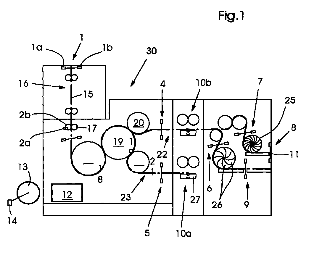
- Fig. 1 is the basic structure of a folder with the respective copy paths assigned sensor pairs shown.
- the material web 15 transported in the conveyor plane 16 passes through Cutting cylinder pair 2b, 17, consisting of a cutting cylinder 2b and one with this cooperating slot cylinder 17. There the individual copies separated from the material web 15 by transverse cutting.
- An encoder 2a can optionally be assigned to the cutting cylinder 2b, which per revolution of the cutting cylinder 2b to the monitoring unit 12 transmitted. For each revolution of the cutting cylinder 2b, exactly one copy of the leading end of the web of material 15 separated, whereby the number of in Folder 30 located copies is easy to determine.
- the number of in The folder entering the folder 30 can alternatively via a rotary encoder 14 are determined, the revolutions of the folder 30 driving Drive motor 13 detects what is also the number of in the folder has entered specimens determined.
- the values for the copies entering the folder are continuously determined and are stored in the monitoring unit 12.
- a folding knife cylinder 18 assigned sensor pair 3 monitors.
- the folding knife cylinder 18 the folding dapper cylinder 19 together, working between them Cylinders 18, 19 of the first cross fold is formed on the copy.
- the jaw cylinder 19 are two further transport or gripper cylinders 20, or 21 assigned, which on the one hand form a further transverse fold in the copy and, on the other hand, the copies of the circumference of the jaw cylinder 19 alternate decrease and in this way cause a distribution of the copy flow.
- An upper conveyor path 22 extends behind the upper transport cylinder 20, secured by a pair of sensors 4 to the upper second longitudinal folding device 10b.
- the lower transport cylinder 21 is a lower conveying path 23 assigned, also secured by a pair of sensors 5, via which the copies are fed to a further second longitudinal folding device 10a.
- the two second longitudinal folding devices 10a, 10b each contain a folding knife 27, which is not closer to the fold back on the copy by pushing in between here shown folding rollers. With the one located over the folding knife 27 Double circles are the drive of the folding knife 27 indicated in a simplified manner.
- the upper second longitudinal fold module 10b is a paddle wheel configuration 24, 25 downstream, with both paddlewheels 24 and 25, respectively, the entry of the specimens by means of a pair of sensors 6 or 7 as well as leaving the specimens of the paddle wheel 26 can be monitored by means of sensor pairs 8 or 9.
- the specimens laid out in shingled formation leave the folder 30 to a stacker or a packaging machine for further processing to become.
- the conveying path 28 indicates the transport path - shown here in greater line width to which the material web 15 through the cutting cylinder pair 2b, 17th Accept severed copies in double parallel fold mode.
- the copies end by the cooperation Folding cylinders 18, 19 and 20 folded in parallel.
- the promotion the specimens take place along the upper conveyor path 22, the upper second Longitudinal folding device 10b is inactive and allows the cross-folded copies to pass through. These can then either in a lower paddle wheel 25 or an upper paddle wheel 24 are passed through which a scaled display of the specimens can be done.
- the sensor pairs 3, 4, 6, 7, 8, and 9 are in detection mode switched while the pair of sensors 5 on the lower conveyor path 23 such is to be switched that this has to detect the absence of specimens.
- the product output take.
- sensors 7 and 8 With a copy output via the upper paddle wheel 25 sensors 7 and 8 must be switched to detection mode - according to the corresponding Validation while sensor pairs 6 and 9 indicate the absence of specimens would have to be set.
- the sensors 7, 8 in the paddle wheel module of the folder 30 are validated in such a way that that the earliest recognize a copy and send a valid signal, if one of the distances from the cutting cylinder pair 2b, 17 to the respective Sensor corresponding number of copies is located in the folder 30. This applies analog for sensors 6 and 9, provided there is also a product delivery via the lower one Paddle wheel 25 is provided.
- sensors 3, 4, 7, 8 and possibly 6 and 9 are dependent from the copy progression of the copies through the folder 30, so that the Signals from the sensors are only considered valid when the respective Depending on the folding mode, detect a sensor at the earliest or not can.
- FIG. 3 shows a specimen conveying path corresponding to the second longitudinal fall mode shown, with the copy flow divided behind the jaw cylinder.
- the paddle wheel module In this operating mode of the folder 30, the paddle wheel module is inactive, the sensors provided there are accordingly inactive, i. e. on detection the absence of copies switched; on the other hand, they are the funding path 29 of the sensor pairs 3, 4 and 5 assigned to the specimens upon detection of the presence of the copies switched, but on the condition that a validity of the specimens detected by the sensor pairs 3, 4 and 5 only from the point in time can take place from which the respective sensor pairs 1, 3, 4 and 5 at the earliest one Recognize the copy according to the copy progression by the folder can.
- the number of folders 30 entering copies via encoder 2a or 14, the cutting cylinder 2b or are assigned to the drive 13 of the folder 30 can be determined as above already set out.
- the monitoring unit 12 is initialized first carries out a self-test 101 and the printer activates it optically or also acoustically.
- the folder configuration is the set folding mode, for example double parallel folding 28 or second longitudinal fold mode 29 detected; this is done in step 102.
- the sensor activation 103 those sensors 3, 4, 5, 6, 7, 8 or 9 activated on the selected folding mode 28 or 29 corresponding conveyance path of the copies through the folder 30 lie.
- memory 104 which is an error detection routine 104.1 is assigned.
- the comparison operation 109 yields a smaller number of by Sensors 3, 4, 5, 6, 7, 8 or 9 detected copies than in the folder 30 have occurred, it is first determined via a sensor validity query 111, whether this result came from a previously validated sensor. if it if the sensor is not valid, the device branches back to Validation request 106; however, the corresponding sensor was correctly validated, a paper jam 111.1 was detected, which was triggered by a shutdown command 112 in disengaging drive 13 of the folder 30 and / or the rotation brings about.
- the monitoring unit 112 When the command 113 is reached, the monitoring unit 112 has the monitoring run through the controlling program.
- the surveillance system After the surveillance system has been initialized, this indicates to the printer that it is is activated in creep speed or during the web retraction phase.
- the system can to monitor yourself, such as when a number of copies are found on a sensor that is larger than that actually entered the folder 30 Number of copies, the function monitoring of the encoder 2a or 14 is displayed becomes.
- the monitoring system can be used in any folder and is next to the specimen jam detection in slow speed or when entering the web also suitable for normal operating speeds and can be configured accordingly.
Landscapes
- Folding Of Thin Sheet-Like Materials, Special Discharging Devices, And Others (AREA)
- Inking, Control Or Cleaning Of Printing Machines (AREA)
- Controlling Sheets Or Webs (AREA)
Abstract
Die Erfindung bezieht sich auf ein Verfahren und einer Vorrichtung zur Überwachung
des Transportes flächiger Exemplare beispielsweise in einen Falzapparat (30),
der einer Rotationsdruckmaschine nachgeordnet ist. Gemäß eines ersten Verfahrensschrittes
werden die Präsenz oder das Fehlen von Exemplaren detektierenden Sensoren
(3, 4, 5, 6, 7, 8 oder 9) je nach Falzmodus (28, 29) ausgewählt. Die Anzahl der in
den Falzapparat (30) eingetretenen Exemplare wird mit Hilfe von Geber (2a, 14)
bestimmt, bevor aus dem Vergleich (109) der Anzahl der in den Falzapparat (30)
eingetretenen Exemplare mit der Anzahl der im Falzapparat (30) durch die Sensoren
(3, 4, 5, 6, 7, 8 und 9) detektierten Exemplare die Auslösung eines Maschinenstops
(112) veranlaßt wird oder unterbleibt.
Description
Die Erfindung bezieht sich auf eine Vorrichtung zur Überwachung des Transportes flächiger Exemplare, beispielsweise in einen Falzapparat von einer Materialbahn abgetrennter und dort längs - und/oder querzufalzender Exemplare.The invention relates to a device for monitoring the transport flat copies, for example in a folder from a material web severed and there to be folded longitudinally and / or transversely.
EP 0847 857 A1 bezieht sich auf eine Justiereinrichtung einer vor einem Zylinder einer Rotationsdruckmaschine angeordneten Traverse. Auf der Traverse ist eine Meßvorrichtung mittels einer Halterung axial zur Mantelfläche des Zylinders verschiebar. Zur genauen, unkomplizierten und automatisierbaren Justierung der Traversenausrichtung bezüglich des Zylinders mit austauschbarer Justierrichtung ist die Halterung mit einem optoelektrischen Justierhilfsgerät kuppelbar. Das Justierhilfsgerät weist ein Lichtstrahlbündel auf den Zylinder projizierendes optisches Element sowie mindestens einen optischen Empfänger auf, der ein von dem Zylinder reflektiertes Lichtstrahlbündel empfängt. Der optische Empfänger umfaßt einen optoelektronischen Sensor, der in Verbindung mit einer Auswerteelektronik zur Erfassung der Lage des reflektierten Lichtstrahlbündel auf dem Sensor geeignet ist.EP 0847 857 A1 relates to an adjustment device in front of a cylinder a traverse arranged in a rotary printing machine. There is one on the traverse Measuring device can be moved axially to the lateral surface of the cylinder by means of a holder. For precise, uncomplicated and automatable adjustment of the truss alignment with respect to the cylinder with interchangeable adjustment direction Bracket can be coupled with an optoelectric adjustment aid. The adjustment aid has a light beam on the cylinder projecting optical element and at least one optical receiver, which is a reflected from the cylinder Beam of light receives. The optical receiver comprises an optoelectronic one Sensor that is used in conjunction with evaluation electronics to record the Position of the reflected light beam on the sensor is suitable.
Diese Vorrichtung dient in erster Linie dem Ausrichten einer die Oberfläche des Zylinders abtastenden optischen Meßeinrichtung. This device is primarily used to align the surface of the cylinder scanning optical measuring device.
EP 0753 409 bezieht sich auf eine Bogendruckmaschine, mit einem Ausleger, auf dessen Oberseite kontinuierlich geförderte Bogen abgelegt werden sollen. In einfacher und die Stapelbildung nicht beeinträchtigender Weise soll ermöglicht werden, mit einer traversirenden Meßvorrichtung einen an der Vorderkante der Bogen aufgebrachten Druckkontrollstreifen abzutasten. Dazu sind der an einer Traverse verfahrbaren Meßvorrichtung Bogenhochhalter zugeordnet, die verhindern, daß die während der Durchführung eines Meßvorganges geförderten Bogen auf der Oberseite des Stapels abgesetzt werden.EP 0753 409 relates to a sheet-fed printing machine with a delivery the top of which should be continuously fed sheets. In simple and not to interfere with stacking, with a traversing measuring device one attached to the leading edge of the sheets To scan pressure control strips. For this purpose, they can be moved on a traverse Measuring device associated with sheet retainers, which prevent the during the execution of a measuring process promoted sheet on the top of the stack.
Mit dieser Vorrichtung aus dem Stand der Technik kann jedoch ein von dem Exemplaren zurückgelegter Förderweg - etwa durch ein Falzapparat - nicht zuverlässig detektiert werden.With this device from the prior art, however, one of the specimens The travel distance traveled - for example by a folder - is not reliable can be detected.
US 3,815,895 offenbart ein Papierstauerkennungssystem für Falzapparate, die einer Rollenrotation nachgeordnet sind. Innerhalb des Falzapparates an ausgewählten Stellen angeordnete Photozellen detektieren sowohl fälschlicherweise abwesende als auch fälschlicherweise vorhandene Exemplare entlang des Förderweges durch den Falzapparate. Eine Zeitablaufkontrolleinheit, welche synchron zum Falzapparat arbeitet, erzeugt Signale, die eine Detektion auslösen, ob ein an einer bestimmten Stelle zu erwartendes Exemplar tatsächlich dort vorliegt und ob ein an einer bestimmten Stelle des Förderweges nicht zu erwartendes Exemplar an dieser Stelle auch tatsächlich nicht eintrifft. Die Signale der Photozellen werden mit denjenigen der Zeitablaufkontrolleinheit logisch verknüpft, einer Logikschaltung zugeführt, die den Falzapparat gegebenenfalls stoppt. Das System erkennt ebenfalls, wenn im Papierstauerkennungssystem eine der Photozellen ausgefallen ist.US 3,815,895 discloses a paper jam detection system for folders, one of which Role rotation are subordinate. Within the folder on selected Locating photocells detect both absent and incorrectly also incorrectly existing copies along the conveyor path through the Folders. A timing control unit that works synchronously with the folder, generates signals that trigger a detection of whether one is on a particular The place where the expected copy actually exists is there and whether it is on a specific one Unexpected copy of the conveyor path at this point actually does not arrive. The signals from the photocells will match those the timing control unit logically linked, supplied to a logic circuit, the stops the folder if necessary. The system also detects when in the paper jam detection system one of the photocells has failed.
Es hat sich herausgestellt, daß nicht nur bei voller Betriebsgeschwindigkeit einer Rollenrotation auftretende Papierstaus im Falzapparat drastische Folgen und lange Ausfallzeiten eine Rotation verursachen können, sondern daß bereits während des Bahneinzuges oder bei Schleichgang der Rotation auftretende Papierstaus oder Papierfehlleitungen zumindest vermeidbare Verzögerungen beim Hochlauf der Rotation verursachen können. Während der Bahneinfädelung oder des Schleichganges der Rotation können sehr hohe Drehmomente auftreten, mechanische Einstellungen von Greifern, Zylindern oder ähnlichen Komponenten in bezug aufeinander können undefiniert sein, während die Aufmerksamkeit der Drucker auf andere in Rahmen einer Neueinrichtung eines Auftrages notwendige Arbeiten gerichtet sein kann.It has been found that not only at full operating speed Roll jams occurring in the folder drastic consequences and long Downtime can cause rotation, but that already during the Web feed or paper jams or paper misfeeds that occur when the rotation is creeping at least avoidable delays in ramping up the rotation can cause. During web threading or creeping the Very high torques can occur, mechanical adjustments of Grippers, cylinders or similar components in relation to each other can be undefined be while the printer's attention to others under one New establishment of an order may be directed to necessary work.
Angesichts der aus dem Stand der Technik skizzierten Lösungen und des aufgezeichneten technischen Problems liegt der Erfindung die Aufgabe zu Grunde, ein Papierlaufüberwachungssystem bereitzustellen, welches bei langsamen Papierföderungsgeschwindigkeiten auf Unregelmäßigkeiten beim Exemplartransport anspricht.In view of the solutions outlined from the prior art and the recorded ones technical problem, the invention is based on the object To provide paper flow monitoring system, which at slow paper feed speeds responds to irregularities in specimen transport.
Erfindungsgemäß wird diese Aufgabe durch die Merkmale des Patentanspruches 1
gelöst.According to the invention, this object is achieved by the features of
Die mit dieser Lösung erziehlbaren Vorteile sind vielfältiger Natur. So lassen sich unter Anwendung des erfindungsgemäßen Verfahrens Falzapparate wesentlich schneller in den Papierlauf bei Schleichgang der vorgeschalteten Rotation einbinden, da fehlgeleitende Exemplare im Falzapparat sofort erkannt werden und zu einer Abschaltung des Falzapparate antriebes fuhren. Dies stellt einen wirksamen Schutz noch undefiniert zueinander eingestellter mechanischer Falzkomponenten zueinander dar, die bei Schleichgang unter den dort auftretenen hohen Drehmomenten erheblich beschädigt werden könnten. Die Drucker können sowohl bei Schleichgang der Rotation als auch während der Papiereinfädelphase die Aufmerksamkeit weiteren notwendigen Voreinstellungen widmen, ein sich ankündigender Papierstau oder eine Exemplarfehlleitung wird nunmehr automatisch erkannt. The advantages that can be achieved with this solution are diverse. So you can using the method according to the invention folders integrate faster into the paper run when the upstream rotation creeps, because misdirected copies are immediately recognized in the folder and cause a shutdown of the folder drive. This provides effective protection mechanical folding components still undefined to each other represents the considerable at creep speed under the high torques occurring there could be damaged. The printer can both at slow speed attention during rotation as well as during the paper threading phase dedicate necessary presets, an impending paper jam or a faulty line is now automatically recognized.
In weiterer Ausgestaltung des der Erfindung zugrunde liegenden Verfahrens werden Sensoren im Falzapparat je nach selektiertem Falzmodus auf Basis der Exemplarprogression entlang des Förderpfades validiert. Die Validation, i.e. eine auf elektronischen Wege herbeiführbare Gültigkeitserklärung eines Sensorsignales, erfolgt bei den am Anfang des Exemplarförderpfades gelegenen Sensoren bereits nach wenigen in den Falzapparat eingetretenen Exemplaren, nachdem der betreffende Sensor ein Exemplar frühestens erkennen kann, je nach mit dem vorgewählten Transportpfad eingestellten Falzmodus. Die Validierung früher im Exemplartransportpfad angeordneter Sensoren erfolgt nach einer geringeren voreinstellbaren Exemplaranzahl, während die Validierung späterer im Exemplartransportpfad angeordneter Sensoren nach einer größeren Anzahl in dem Falzapparat eingetretener Exemplare erfolgt, entsprechend der bis zum validierenden Sensor zurückgelegten Wegstrecke.In a further embodiment of the method on which the invention is based Sensors in the folder depending on the selected folding mode based on the copy progression validated along the funding path. The validation, i.e. one on electronic Declaration of validity of a sensor signal can be made at the sensors located at the beginning of the specimen conveying path after just a few copies entered in the folder after the sensor in question Can recognize the earliest at the earliest, depending on the preselected transport path set folding mode. Validation arranged earlier in the item transport path Sensors takes place after a lower number of copies that can be preset the validation of later sensors arranged in the specimen transport path corresponding to a larger number of copies entered in the folder the distance covered up to the validating sensor.
Die die Validierung ermöglichenden Grenzwerte sind an der Überwachungseinheit vorgebbar und dort gespeichert, so daß sie stets aktuell für die notwendigen Berechnungen zur Verfügung stehen.The limit values that enable validation are on the monitoring unit can be specified and stored there so that it is always up to date for the necessary calculations be available.
Durch die Validierung der zum gewählten Falzmodus korrespondierenden Sensoren entlang des mit dem Falzmodus verbundenen Förderweges der Exemplare ist die Zuverlässigkeit der von den Sensoren an die Überwachungseinheit übermittelten Signale gewährleistet. Die Bestimmung der Anzahl von Exemplare, die in den Falzapparat eingetreten ist, erfolgt durch beispielsweise dem Schneidzylinder zugeordnete Geber oder dem Antriebsmotor des Falzapparates zugeordnete Umdrehungszähler. Je nach gewählter Abschnittslänge kann so individuell die in den Falzapparat transportierte Exemplaranzahl bestimmt werden.By validating the sensors corresponding to the selected folding mode along the conveying path of the copies associated with the folding mode is the Reliability of those transmitted from the sensors to the monitoring unit Signals guaranteed. Determining the number of copies in the Folding device has occurred, for example, is assigned to the cutting cylinder Revolution counter associated with the encoder or the drive motor of the folder. Depending on the selected section length, the individual in the Folders transported number of copies can be determined.
In der Überwachungseinheit wird gemäß des vorliegenden Verfahrens die Differenz von pro validiertem Sensor detektierter Exemplaranzahl und aus dem Falzapparat befindlicher Exemplaranzahl kontinuierlich bestimmt, wobei eine maximal zulässige Differenz an der Überwachungseinheit vorgegeben werden kann. Diese kann Abhängig vom Bedruckstoffparameter, Exemplardicke und Erfahrungswerten vorgegeben werden, um das Überwachungssystem auftragsgerecht einzustellen.The difference is in the monitoring unit according to the present method of the number of copies detected per validated sensor and from the folder number of copies located is determined continuously, with a maximum permissible Difference can be specified on the monitoring unit. This can be dependent from the substrate parameters, copy thickness and empirical values to set the monitoring system according to the order.
Bei der zur Durchführung des erfindungsgemäßen Verfahrens erforderlichen Sensorik handelt es sich bevorzugt um Sensorpaare, die aus einem Sende- und einem Empfangsteil bestehen. Diese sind zueinander beabstandet, wobei zwischen Sende und Empfangsteil der Förderpfad der Exemplare verläuft. Die den Schneidzylinder bzw. dem Antrieb des Falzapparates zugeordneten Geber können als Näherungsschalter oder Encoder wie Drehgeber beispielsweise ausgestaltet sein, die pro Umdrehung des betreffenden Aggregates einen Zählimpuls an die Überwachungseinheit übermitteln, der dort summiert wird.In the sensors required to carry out the method according to the invention it is preferably sensor pairs consisting of a transmit and a Receiving part exist. These are spaced from each other, being between transmit and the receiving section of the specimen conveyor path. The cutting cylinder or the drive assigned to the folder can be used as a proximity switch or encoders such as rotary encoders, for example, are configured per revolution a pulse to the monitoring unit of the unit concerned submit, which is summed up there.
Mittels der erfindungsgemäßen Lösung lassen sich bevorzugt Falzapparate überwachen, die einer Rollenrotation nachgeordnet sind, wobei die Überwachungseinheit je nach für den gewählten Falzmodus erforderlichem Exemplarförderpfad die erforderlichen Sensoren validiert und die solcherart validierten Sensorsignale für die Anzahl der Exemplare mit derjenigen vergleicht, die in den Falzapparat eingetreten ist. Aus diesem in Echtzeit vorgenommenen Vergleich kann eine Abschaltbedingung in dem Falzapparat und/oder für die gesamte Rotation abgeleitet werden.Folders can preferably be monitored by means of the solution according to the invention, which are subordinate to a roll rotation, the monitoring unit each according to the copy path required for the selected folding mode Validated sensors and the sensor signals validated in this way for the number who compares the copies with the one that entered the folder. Out this comparison made in real time can be a shutdown condition in the Folder and / or derived for the entire rotation.
Anhand einer Zeichnung wird die Erfindung nachstehend detailiert erläutert:The invention is explained in detail below with reference to a drawing:
Es zeigt:
- Fig. 1
- dem prinzipiellen Aufbau eines Falzapparates mit dem jeweiligen Exemplarförderpfades zugeordneten Sensorpaaren,
- Fig. 2
- einen dem Doppelparallelfalzmodus entsprechende Exemplarförderung durch den Falzapparat,
- Fig. 3
- ein dem zweiten Längsfalzmodus entsprechender Exemplartransport durch den Falzapparat mit sich aufteilendem Exemplarstrom und
- Fig. 4
- ein prinzipielles, vereinfacht wiedergegebenes Flußschaltbild, welches die Arbeitsweise der Steuereinheit verdeutlicht.
- Fig. 1
- the basic structure of a folder with the sensor pairs assigned to the respective specimen conveying path,
- Fig. 2
- a copy conveyance by the folder corresponding to the double parallel folding mode,
- Fig. 3
- a copy transport corresponding to the second longitudinal folding mode through the folder with a dividing copy stream and
- Fig. 4
- a basic, simplified flow diagram, which illustrates the operation of the control unit.
In Fig. 1 ist der prinzipielle Aufbau eines Falzapparates mit den jeweiligen Exemplarförderpfaden zugeordneten Sensorpaaren dargestellt.In Fig. 1 is the basic structure of a folder with the respective copy paths assigned sensor pairs shown.
Eine Materialbahn 15, die auch aus mehreren Materialbahnlagen gebildet sein kann,
tritt nach Passage eines hier nicht näher dargestellten Wendestangenüberbaus mit
einen 1. Längsfalz versehen in den Falzapparates 30 ein. Ihre Präsenz wird durch ein
Sensorpaar 1 detektiert, welches aus einem Sende- und einem Empfangsteil 1a, bzw.
1b besteht. Die in der Förderebene 16 transportierte Materialbahn 15 passiert ein
Schneidzylinderpaar 2b, 17, bestehend aus einen Schneidzylinder 2b und einem mit
diesem zusammenarbeitenden Nutenzylinder 17. Dort werden die einzelnen Exemplare
durch Querschneiden der Materialbahn 15 von dieser abgetrennt.A
Dem Schneidzylinder 2b kann optional ein Geber 2a zugeordnet sein, der pro Umdrehung
des Schneidzylinders 2b einen Zählimpuls an die Überwachungseinheit 12
übermittelt. Pro Umdrehung des Schneidzylinders 2b wird genau ein Exemplar vom
vorlaufenden Ende der Materialbahn 15 abgetrennt, wodurch die Anzahl der im
Falzapparat 30 befindlichen Exemplare einfach bestimmbar ist. Die Anzahl der in
dem Falzapparat 30 eintretenden Exemplare können alternativ über einen Drehgeber
14 bestimmt werden, der die Umdrehungen des den Falzapparat 30 antreibenden
Antriebsmotor 13 erfaßt, worauf sich ebenfalls die Anzahl der in den Falzapparat
eingetretenen Exemplare bestimmen läßt. Die auf diese Weise erhaltenen Werte für
die in den Falzapparat eingetretenen Exemplare werden kontinierlich bestimmt und
werden in der Überwachungseinheit 12 abgespeichert.An
Die weitere Förderung der Exemplare wird nun durch ein einem Falzmesserzylinder
18 zugeordnetes Sensorpaar 3 überwacht. Mit dem Falzrmesserzylinder 18 arbeitet
der Falzldappenzylinder 19 zusammen, wobei zwischen diesen zusammenarbeitenden
Zylindern 18, 19 der 1. Querfalz am Exemplar ausgebildet wird. Dem Falzklappenzylinder
19 sind zwei weitere Transport- beziehungsweise Greiferzylinder 20,
bzw. 21 zugeordnet, die zum einen im Exemplar einen weiteren Querfalz ausbilden
und andererseits die Exemplare vom Umfang des Falzklappenzylinders 19 alternierend
abnehmen und auf diese Weise eine Aufteilung des Exemplarstroms bewirken.The further promotion of the copies is now done by a
Hinter dem oberen Transportzylinder 20 erstreckt sich ein oberer Förderpfad 22,
abgesichert durch ein Sensorpaares 4 zur oberen zweiten Längsfalzeinrichtung 10b.
In dazu analoger Weise ist dem unteren Transportzylinder 21 ein unterer Förderpfad
23 zugeordnet, ebenfalls abgesichert durch ein Sensorpaar 5, über welchen die Exemplare
einer weiteren zweiten Längfalzeinrichtung 10a zugeführt werden. Die beiden
zweiten Längsfalzeinrichtungen 10a, 10b enthalten jeweils ein Falzmesser 27,
welches den Falzrücken am Exemplar durch Einstoßen zwischen hier nicht näher
dargestellten Falzwalzen ausbildet. Mit dem über den Falzmesser 27 jeweils befindlichen
Doppelkreisen sei der Antrieb der Falzmesser 27 vereinfacht angedeutet.An
Dem oberen zweiten Längsfalzmodul 10b ist eine Schaufelrad Konfiguration 24,25
nachgeschaltet, wobei sowohl je Schaufelrad 24, bzw. 25 der Eintritt der Exemplare
mittels eines Sensorpaares 6 bzw 7 als auch das Verlassen der Exemplare der Schaufelrades
26 mittels Sensorpaaren 8 beziehungsweise 9 überwachbar ist. An der Ausgabe
11 verlassen die in geschuppter Formation ausgelegten Exemplare den Falzapparat
30, um einen Stacker oder eine Paketiermaschine zur Weiterverarbeitung zugeführt
zu werden.The upper second
Die Fig. 2 zeigt eine dem Doppelparallelfalzmodus entsprechende Exemplarförderung durch den Falzapparat.2 shows a copy conveyance corresponding to the double parallel folding mode through the folder.
Der Förderpfad 28 deutet ― hier in stärker Strichstärke wiedergegeben ― den Transportpfad
an, den die von der Materialbahn 15 durch das Schneidzylinderpaar 2b, 17
abgetrennter Exemplare im Doppelparallelfalzmodus annehmen. In diesen Betriebsmodus
des Falzapparates 30 werden die Exemplare durch die miteinander Zusammenarbeitenden
Falzzylinder 18, 19 und 20 doppelparallelgefalzt. Die Förderung
der Exemplare erfolgt entlang des oberens Förderpfades 22, wobei die obere zweite
Längsfalzeinrichtung 10b inaktiv ist und die quergefalzten Exemplare passieren läßt.
Diese können dann wahlweise in ein unteres Schaufelrad 25 oder ein oberes Schaufelrad
24 geleitet werden, durch welche dann eine geschuppte Auslage der Exemplare
erfolgen kann. In diesem Falzmodus, der eine Förderung der Exemplare gemäß
des Förderweges 28 erzwingt, sind die Sensorpaare 3, 4, 6, 7, 8, und 9 auf Detektionsmodus
geschaltet, während das Sensorpaar 5 am unteren Förderpfades 23 derart
zu schalten ist, daß dies die Abwesenheit von Exemplaren zu detektieren hat. Je nach
gewählter Auslagekonfiguration für die Exemplare im Doppelparallelfalzmodus
kann eines der Schaufelräder 24 bzw. 25 oder können beide Schaufelräder die Produktausgabe
übernehmen. Bei einer Exemplarausgabe über das obere Schaufelrad 25
sind die Sensoren 7 und 8 auf Detektionsmodus zu schalten ― nach entsprechender
Validierung, während die Sensorpaare 6 und 9 auf die Abwesenheit von Exemplaren
einzustellen wären.The conveying
Die Sensoren 7, 8 im Schaufelradmodul des Falzapparates 30 werden derart validiert,
daß dieser ein Exemplar frühestens erkennen und ein gültiges Signal absetzen,
wenn sich eine der Wegstrecke vom Schneidzylinderpaar 2b, 17 bis zum jeweiligen
Sensor entsprechende Anzahl von Exemplaren im Falzapparat 30 befindet. Dies gilt
analog für die Sensoren 6 und 9, sofern auch eine Produktauslage über das untere
Schaufelrad 25 vorgesehen ist.The
Die Validierung der Sensoren 3, 4, 7, 8 und gegebenenfalls 6 und 9 erfolgt abhängig
von der Exemplarprogression der Exemplare durch den Falzapparat 30, so daß die
Signale der Sensoren erst dann für gültig angesehen werden, wenn der jeweilige
Sensor je nach Falzmodus frühestens ein Exemplar detektieren oder nicht detektieren
kann.The validation of
In Fig.3 ist eine dem zweiten Längsfallmodus entsprechender Exemplarförderpfad dargestellt, wobei sich der Exemplarstrom hinter den Falzklappenzylinder teilt.3 shows a specimen conveying path corresponding to the second longitudinal fall mode shown, with the copy flow divided behind the jaw cylinder.
In diesem Betriebsmodus des Falzapparates 30, dessen Exemplarförderpfade mit
Bezugszeichen 29 gekennzeichnet sind, werden die Exemplare einmal quergefalzt
hinter den Falzklappenzylinder 19 durch die Zylinder 20, 21 alternierend abgegriffen
und gelangen über den unteren beziehungsweise den oberen Förderpfades 22, 23 in
die obere bzw. die untere zweite Längsfalzeinrichtung 10a, 10b. Dort werden die
quergefalzten Exemplaren mit einen zweiten Längsfalz versehen und gelangen in
eine nicht näher dargestellte Auslage.In this operating mode of the
In diesen Betriebsmodus des Falzapparates 30 ist das Schaufelradmodul inaktiv,
dementsprechend sind die dort vorgesehenen Sensoren inaktiv, i. e. auf Erkennung
der Abwesenheit von Exemplaren geschaltet; hingegen sind die dem Förderpfad 29
der Exemplaren zugeordneten Sensorpaare 3, 4, und 5 auf Erkennung des Vorhandenseins
der Exemplare geschaltet, jedoch unter der Bedingung, daß eine Gültigkeit
der durch die Sensorpaare 3, 4 und 5 detektierte Exemplare erst ab dem Zeitpunkte
erfolgen können, ab dem die jeweiligen Sensorpaare 1, 3, 4 und 5 frühestens eine
Exemplar entsprechend der Exemplarprogresson durch den Falzapparat erkennen
können.In this operating mode of the
In der Konfiguration gemäß Fig.2 und 3 kann die Anzahl der in den Falzapparat 30
eintretenden Exemplare über Geber 2a bzw. 14, die dem Schneidzylinder 2b oder
dem Antrieb 13 des Falzapparates 30 zugeordnet sind, bestimmt werden, wie oben
bereits dargelegt.In the configuration according to FIGS. 2 and 3, the number of
Die Funktionsweise der in den Falzapparat 30 integrierten gemäß den Figuren 1 bis
3 dargestellten Überwachungseinheit 12 läßt sich am besten anhand des Flußdiagramms
gemäß Fig. 4 erläutern.The operation of the integrated in the
Mit dem Startbefehl 100 erfolgt eine Initialisierung der Überwachungseinheit 12, die
zunächst einen Selbsttest 101 durchführt und dem Drucker ihre Aktivierung auf optischem
oder auch auf akustischem Wege anzeigt. Entsprechend der vorgegebenen
Falzapparatkonfiguration wird der eingestellte Falzmodus, beispielsweise Doppelparallelfalz
28 oder zweiter Längsfalzmodus 29 erkannt; dies erfolgt in Schritt 102;.
je nach selektierten Falzmodus 28 bzw. 29 werden durch die Sensoraktivierung 103
diejenigen Sensoren 3, 4, 5, 6, 7, 8 oder 9 aktiviert, die am den ausgewählten Falzmodus
28 oder 29 entsprechenden Förderpfad der Exemplare durch den Falzapparat
30 liegen. Diese werden im Speicher 104 abgelegt, dem eine Fehlererkennungroutine
104.1 zugeordnet ist.With the
Sind die relevanten der Sensoren aus der Sensoranzahl 3, 4, 5, 6, 7, 8, oder 9 aktiviert
und abgespeichert, wird in der Zähistufe 105 die Exemplaranzahl ermittelt, die
in den Falzapparat 30 eingetreten ist. Are the relevant sensors from the number of
Der nachfolgende Teil des Diagramms zwischen Zählstufe 105 und der Validierroutine
106 wird für jeden Sensor 3, 4, 5, 6, 7, 8, oder 9 separat durchgeführt, da jeder
dieser Sensoren kraft seiner unterschiedlichen Positionen im Falzapparat 30 eine
andere Validierschwelle hat. Nach Überschreiten der jeweiligen Validierschwellel,
dem Zeitpunkt, ab dem der ausgewählte Sensor frühestens ein Exemplar erkennen
oder das Fehlendes Exemplares erkennen kann, wird das entsprechende Sensorsignal
erst als gültiges Sensorsignal anerkannt dies erfolgt durch das Setzen der Sensoren in
107.The following part of the diagram between
Danach wird je nach Falzmodus selektierten Sensoren eine Vergleichoperation 108
zwischen der im Falzapparat 30 befindlichen Anzahl Exemplare und der am jeweiligen
Sensor erkannten Anzahl von Exemplaren durchgeführt. Ergibt sich bei der in
Echtzeit durchgeführt Vergleichsoperation 109 keine Differenz, wird erneut zur Signalgültigkeitsanfrage
106 verzweigt, um abzuprüfen, ob die Validierungschwelle
tatsächlich überschritten wurde oder nicht.Then, depending on the folding mode selected sensors, a
Ergibt der Vergleich 109, daß am jeweiligen Sensor mehr Exemplare gezählt wurden,
als in den Falzapparat eingetreten sein können, erfolgt durch das Setzen des
Abschaltssignales 110 ein Stop des Falzapparat 30 und/oder der Rotation da eine
Fehlfunktion der Geber 2a bzw. 14 vorliegen könnte.If the
Ergibt die Vergleichoperation 109 hingegen eine geringere Anzahl von durch die
Sensoren 3, 4, 5, 6, 7, 8 oder 9 detektierten Exemplare als in dem Falzapparat 30
eingetreten sind, so wird zunächst über eine Sensorgültigkeitsabfrage 111 ermittelt,
ob dieses Ergebnis mittels eines zuvor validierten Sensors zustande kam. Falls es
sich um einen nicht validieten Sensor handelt, erfolgt eine Rückverzweigung zur
Validierungsabrage 106; war der entsprechende Sensor hingegen korrekt validiert,
wurde ein Papierstau 111.1 festgestellt, der über einen Abschaltbefehl 112 in ein
abschaltendes Antriebes 13 des Falzapparates 30 und/oder der Rotation herbeiführt. On the other hand, the
Mit Erreichen des Befehles 113 hat die Überwachungseinheit 112 das die Überwachung
steuernde Programm durchlaufen.When the
Nach Initialisierung des Überwachungssystem zeigt diese dem Drucker an, daß es
im Schleichgang oder während der Bahneinzugphase aktiviert ist. Das System vermag
sich selbst zu Überwachen, derart das bei Feststellung einer Anzahl Exemplare
an einem Sensor, die größer ist, als die in den Falzapparat 30 tatsächlich eingetretener
Exemplaranzahl, die Funktionsüberwachung des Drehgebers 2a oder 14 angezeigt
wird. Das Überwachungssystem kann in jeden Falzapparat eingesetzt werden
und ist neben der Exemplarstauerkennung im Schleichgang oder bei Bahneinzug
auch für normale Betriebsgeschwindigkeiten geeignet und entsprechend konfigurierbar. After the surveillance system has been initialized, this indicates to the printer that it is
is activated in creep speed or during the web retraction phase. The system can
to monitor yourself, such as when a number of copies are found
on a sensor that is larger than that actually entered the
- 11
- SensorpaarSensor pair
- 1a1a
- SendeteilTransmitting part
- 1b1b
- EmpfangsteilReceiving part
- 2a2a
- UmdrehungszählerRevolution counter
- 2b2 B
- SchneidzylinderCutting cylinder
- 33rd
- Sensorpaar FalzzylinderSensor pair of folding cylinders
- 44th
- Sensorpaar oberer FörderpfadSensor pair upper conveyor path
- 55
- Sensorpaar unterer FörderpfadSensor pair lower conveyor path
- 66
- Sensorpaar 1. SchaufelradSensor pair 1st paddle wheel
- 77
- Sensorpaar 2. SchaufelradSensor pair 2nd paddle wheel
- 88th
- Sensorpaar oberer AuslagePair of sensors on top display
- 99
- Sensorpaar untere AuslageLower delivery sensor pair
- 10a10a
- untere zweite Längsfalzeinrichtunglower second longitudinal folding device
- 10b10b
- obere zweite Längsfalzeinrichtungupper second longitudinal folding device
- 1111
- Ausgabeoutput
- 1212th
- ÜberwachungseinheitMonitoring unit
- 1313
- Antriebdrive
- 1414
- UmdrehungszählerRevolution counter
- 1515
- MaterialbahnMaterial web
- 1616
- FörderebeneFunding level
- 1717th
- MutenzylinderMut cylinder
- 1818th
- FalzmesserzylinderFolding knife cylinder
- 1919th
- FalzklappenzylinderJaw cylinder
- 2020th
- TransportzylinderTransport cylinder
- 2222
- oberer Förderpfadupper funding path
- 2323
- unterer Förderpfadlower conveyor path
- 2424th
- SchaufelradPaddle wheel
- 2525th
- SchaufelradPaddle wheel
- 2626
- Schaufelradtaschen Paddle wheel bags
- 2727
- Falzmesser zweiter LängsfalzFolding knife second longitudinal fold
- 2828
- Falzapparatmodus DoppelparallelfalzFolder mode double parallel fold
- 2929
- Falzapparatmodus zweiter Längsfalz gesplittertFolder mode second longitudinal fold splintered
- 3030th
- FalzapparatFolder
- 100100
- Startbegin
- 101101
- Aktivierungactivation
- 102102
- Falzapparat KonfigurationserkennungFolder configuration detection
- 103103
- SensoraktivierungSensor activation
- 104104
- SpeicherabfrageMemory query
- 104.1104.1
- SpeicherfehlerroutineMemory error routine
- 105105
- ExemplarzählungCopy count
- 106106
- Signalgültigkeitsabfrage, ValidierungSignal validity query, validation
- 107107
- SensoraktivierungSensor activation
- 108108
- VergleicherComparator
- 109109
- DefferentwertermittlungDefferentwertung
- 110110
- AbschaltauslösungShutdown triggering
- 111111
- SensorgültigieitsabfrageSensor validity query
- 111.1111.1
- PapierstauPaper Jam
- 112112
- AbschaltbefehlShutdown command
- 113113
- EndeThe End
Claims (18)
Applications Claiming Priority (4)
| Application Number | Priority Date | Filing Date | Title |
|---|---|---|---|
| DE19933287A DE19933287A1 (en) | 1999-07-15 | 1999-07-15 | Flat form transport monitoring method e.g. for folding machine at output of rotary printing press compares indicated number of handled forms with number of forms detected by spaced sensors |
| DE19933287 | 1999-07-15 | ||
| FR0004400A FR2796331B3 (en) | 1999-07-15 | 2000-04-06 | METHOD AND DEVICE FOR MONITORING THE TRANSPORT OF PRINTED OR SIMILAR PRODUCTS, AS WELL AS FOLDER AND ROTARY PRINTING MACHINE USING THE SAME |
| FR0004400 | 2000-04-06 |
Publications (3)
| Publication Number | Publication Date |
|---|---|
| EP1069062A2 true EP1069062A2 (en) | 2001-01-17 |
| EP1069062A3 EP1069062A3 (en) | 2002-01-30 |
| EP1069062B1 EP1069062B1 (en) | 2004-01-02 |
Family
ID=26054207
Family Applications (1)
| Application Number | Title | Priority Date | Filing Date |
|---|---|---|---|
| EP00114164A Expired - Lifetime EP1069062B1 (en) | 1999-07-15 | 2000-07-12 | Device for monitoring the transport of flat signatures |
Country Status (3)
| Country | Link |
|---|---|
| US (1) | US6446961B1 (en) |
| EP (1) | EP1069062B1 (en) |
| AT (1) | ATE257120T1 (en) |
Cited By (3)
| Publication number | Priority date | Publication date | Assignee | Title |
|---|---|---|---|---|
| DE10207869A1 (en) * | 2002-02-23 | 2003-09-04 | Heidelberger Druckmasch Ag | Folder of a web-processing printing machine with a conveyor belt monitoring device |
| DE102008029966A1 (en) * | 2008-06-26 | 2009-12-31 | Manroland Ag | Web Press |
| EP4232389A1 (en) * | 2020-10-21 | 2023-08-30 | Bobst Mex Sa | Sheet processing machine |
Families Citing this family (5)
| Publication number | Priority date | Publication date | Assignee | Title |
|---|---|---|---|---|
| DE10116346B4 (en) * | 2001-04-02 | 2006-03-02 | Koenig & Bauer Ag | folding |
| US6884209B2 (en) * | 2002-09-10 | 2005-04-26 | American Trade Names & Patents Llc | Apparatus and method for folding and stacking napkins |
| US7008364B2 (en) * | 2002-09-27 | 2006-03-07 | C.G. Bretting Manufacturing Company, Inc. | Sheet folding apparatus and method |
| JP2005314090A (en) * | 2004-04-30 | 2005-11-10 | Komori Corp | Parallel folding device of folding machine |
| US10449746B2 (en) | 2016-06-27 | 2019-10-22 | C. G. Bretting Manufacturing Co., Inc. | Web processing system with multiple folding arrangements fed by a single web handling arrangement |
Family Cites Families (11)
| Publication number | Priority date | Publication date | Assignee | Title |
|---|---|---|---|---|
| US3815895A (en) * | 1970-12-07 | 1974-06-11 | Harris Intertype Corp | Jam detector system |
| US4085928A (en) * | 1976-01-02 | 1978-04-25 | Arthur Sussman | Folding system with photoelectric detection means |
| JP2758003B2 (en) * | 1988-09-30 | 1998-05-25 | 株式会社リコー | Image forming device |
| DE3935056C2 (en) * | 1989-10-20 | 1996-07-11 | Stahl Gmbh & Co Maschf | Process for controlling sheet travel in a folding machine and device for carrying out the process |
| DE4125465A1 (en) * | 1991-08-01 | 1993-02-04 | Zirkon Druckmaschinen Gmbh | TRANSPORT DEVICE FOR CONVERSING CROSS-FOLDED PRINTED PRODUCTS TO THE THIRD FOLD |
| US5217220A (en) * | 1991-08-19 | 1993-06-08 | Carlson Herbert L | Diverter for a printing press |
| US5262637A (en) * | 1992-08-07 | 1993-11-16 | Motorola, Inc. | Reprographic media detector and methods for making and using |
| JPH0885671A (en) * | 1994-09-16 | 1996-04-02 | Toshiba Corp | Image forming device |
| DE19525492C1 (en) | 1995-07-13 | 1996-12-12 | Roland Man Druckmasch | Device for measuring in the delivery of a sheet printing machine |
| KR0171545B1 (en) * | 1996-01-12 | 1999-05-01 | 김광호 | Printing system by paper lenght automatic sensing and controlling method thereof |
| DE19651193A1 (en) | 1996-12-10 | 1998-06-18 | Roland Man Druckmasch | Adjustment device of a traverse arranged in front of a cylinder of a rotary printing press |
-
2000
- 2000-07-12 AT AT00114164T patent/ATE257120T1/en not_active IP Right Cessation
- 2000-07-12 EP EP00114164A patent/EP1069062B1/en not_active Expired - Lifetime
- 2000-07-17 US US09/617,655 patent/US6446961B1/en not_active Expired - Fee Related
Cited By (6)
| Publication number | Priority date | Publication date | Assignee | Title |
|---|---|---|---|---|
| DE10207869A1 (en) * | 2002-02-23 | 2003-09-04 | Heidelberger Druckmasch Ag | Folder of a web-processing printing machine with a conveyor belt monitoring device |
| EP1338539A3 (en) * | 2002-02-23 | 2004-06-09 | Heidelberger Druckmaschinen Aktiengesellschaft | Folding device of a printing machine for handling webs with a transport belt monitoring device |
| US6979815B2 (en) | 2002-02-23 | 2005-12-27 | Goss International Montataire, S.A. | Folding apparatus of a web-fed printing press including a conveyor belt monitoring device |
| DE102008029966A1 (en) * | 2008-06-26 | 2009-12-31 | Manroland Ag | Web Press |
| EP4232389A1 (en) * | 2020-10-21 | 2023-08-30 | Bobst Mex Sa | Sheet processing machine |
| US12534329B2 (en) | 2020-10-21 | 2026-01-27 | Bobst Mex Sa | Sheet processing machine |
Also Published As
| Publication number | Publication date |
|---|---|
| ATE257120T1 (en) | 2004-01-15 |
| EP1069062B1 (en) | 2004-01-02 |
| EP1069062A3 (en) | 2002-01-30 |
| US6446961B1 (en) | 2002-09-10 |
Similar Documents
| Publication | Publication Date | Title |
|---|---|---|
| EP3077307B1 (en) | Delivery unit of a sheet-processing machine and method for operating a sheet-processing machine | |
| EP3354426B1 (en) | Position correction for registration marks when cutting corrugated cardboard | |
| EP2958744A1 (en) | System for processing a paper web or corrugated cardboard web | |
| EP3224169B1 (en) | Sheet-processing machine having a deliverer, and method for depositing sheets | |
| EP3507097A1 (en) | Sheet processing machine and method for monitoring sheet travel | |
| EP2055657B1 (en) | Method for controlling the feed of sheets into a sheet-fed printing press | |
| EP1069062B1 (en) | Device for monitoring the transport of flat signatures | |
| DE10338973A1 (en) | Detecting interruption in material web transport by sensor unit monitoring print-to-cut registration marks and providing alarm signal if predetermined threshold values are overstepped | |
| EP0771753A1 (en) | Phase-regulating system for paddle wheel devices of folding apparatuses | |
| EP2489616A2 (en) | Feeder for a printer and method of operating such | |
| EP0453909B1 (en) | Method for adjusting and controlling a folding machine | |
| EP2316766B1 (en) | Diverter station for cardboard blanks and method for producing and diverting cardboard blanks | |
| DE19734137C2 (en) | Device for preventing printing unit damage | |
| DE19933287A1 (en) | Flat form transport monitoring method e.g. for folding machine at output of rotary printing press compares indicated number of handled forms with number of forms detected by spaced sensors | |
| DE10348029A1 (en) | Sheet feeding control method for use with a printer sheet feeder, wherein sheet dimensions are input prior to printing and upon detection of a miss-feed a controller stops feeding in a manner matched to sheet size | |
| EP4389664B1 (en) | Sheet folding machine with waste sheet discharging | |
| EP3059195A1 (en) | Folding device and method | |
| DE102015209905B4 (en) | Control device for monitoring a limit value of a layer thickness and / or a number of several at least partially superimposed material sections in a sensing gap | |
| EP2108511B1 (en) | Cut register regulation | |
| DE19743020C2 (en) | Device and method for separating printed products | |
| DE102017208165B4 (en) | Sheet processing machine with sheet guide cylinders and a delivery and method for operating a sheet processing machine | |
| DE102007009675B4 (en) | Method and device for setting a double sheet control device | |
| DE10140101B4 (en) | The sheet stacking | |
| DE102011087623A1 (en) | Sheet feeding apparatus for sheet rotary offset printing machine, has measuring unit reciprocally co-operating with axles i.e. tubular bars, of multi-sheet controller for detecting axle movement, where axles are arranged over machine width | |
| DE102009002755A1 (en) | Method for ground control in ground processing machine, particularly sheet-fed letterpress rotary, involves continuous scanning of height profile of sheet sequence and continuous processing of detected profile height |
Legal Events
| Date | Code | Title | Description |
|---|---|---|---|
| PUAI | Public reference made under article 153(3) epc to a published international application that has entered the european phase |
Free format text: ORIGINAL CODE: 0009012 |
|
| AK | Designated contracting states |
Kind code of ref document: A2 Designated state(s): AT BE CH CY DE DK ES FI FR GB GR IE IT LI LU MC NL PT SE |
|
| AX | Request for extension of the european patent |
Free format text: AL;LT;LV;MK;RO;SI |
|
| PUAL | Search report despatched |
Free format text: ORIGINAL CODE: 0009013 |
|
| AK | Designated contracting states |
Kind code of ref document: A3 Designated state(s): AT BE CH CY DE DK ES FI FR GB GR IE IT LI LU MC NL PT SE |
|
| AX | Request for extension of the european patent |
Free format text: AL;LT;LV;MK;RO;SI |
|
| 17P | Request for examination filed |
Effective date: 20020327 |
|
| AKX | Designation fees paid |
Free format text: AT BE CH CY DE DK ES FI FR GB GR IE IT LI LU MC NL PT SE |
|
| 17Q | First examination report despatched |
Effective date: 20030207 |
|
| GRAP | Despatch of communication of intention to grant a patent |
Free format text: ORIGINAL CODE: EPIDOSNIGR1 |
|
| GRAS | Grant fee paid |
Free format text: ORIGINAL CODE: EPIDOSNIGR3 |
|
| GRAA | (expected) grant |
Free format text: ORIGINAL CODE: 0009210 |
|
| AK | Designated contracting states |
Kind code of ref document: B1 Designated state(s): AT BE CH CY DE DK ES FI FR GB GR IE IT LI LU MC NL PT SE |
|
| PG25 | Lapsed in a contracting state [announced via postgrant information from national office to epo] |
Ref country code: NL Free format text: LAPSE BECAUSE OF FAILURE TO SUBMIT A TRANSLATION OF THE DESCRIPTION OR TO PAY THE FEE WITHIN THE PRESCRIBED TIME-LIMIT Effective date: 20040102 Ref country code: FI Free format text: LAPSE BECAUSE OF FAILURE TO SUBMIT A TRANSLATION OF THE DESCRIPTION OR TO PAY THE FEE WITHIN THE PRESCRIBED TIME-LIMIT Effective date: 20040102 Ref country code: IE Free format text: LAPSE BECAUSE OF FAILURE TO SUBMIT A TRANSLATION OF THE DESCRIPTION OR TO PAY THE FEE WITHIN THE PRESCRIBED TIME-LIMIT Effective date: 20040102 Ref country code: ES Free format text: LAPSE BECAUSE OF FAILURE TO SUBMIT A TRANSLATION OF THE DESCRIPTION OR TO PAY THE FEE WITHIN THE PRESCRIBED TIME-LIMIT Effective date: 20040102 Ref country code: CY Free format text: LAPSE BECAUSE OF FAILURE TO SUBMIT A TRANSLATION OF THE DESCRIPTION OR TO PAY THE FEE WITHIN THE PRESCRIBED TIME-LIMIT Effective date: 20040102 |
|
| REG | Reference to a national code |
Ref country code: GB Ref legal event code: FG4D Free format text: NOT ENGLISH |
|
| REG | Reference to a national code |
Ref country code: CH Ref legal event code: EP |
|
| REG | Reference to a national code |
Ref country code: IE Ref legal event code: FG4D Free format text: GERMAN |
|
| REF | Corresponds to: |
Ref document number: 50004908 Country of ref document: DE Date of ref document: 20040205 Kind code of ref document: P |
|
| GBT | Gb: translation of ep patent filed (gb section 77(6)(a)/1977) |
Effective date: 20040217 |
|
| PG25 | Lapsed in a contracting state [announced via postgrant information from national office to epo] |
Ref country code: DK Free format text: LAPSE BECAUSE OF FAILURE TO SUBMIT A TRANSLATION OF THE DESCRIPTION OR TO PAY THE FEE WITHIN THE PRESCRIBED TIME-LIMIT Effective date: 20040402 Ref country code: SE Free format text: LAPSE BECAUSE OF FAILURE TO SUBMIT A TRANSLATION OF THE DESCRIPTION OR TO PAY THE FEE WITHIN THE PRESCRIBED TIME-LIMIT Effective date: 20040402 Ref country code: GR Free format text: LAPSE BECAUSE OF FAILURE TO SUBMIT A TRANSLATION OF THE DESCRIPTION OR TO PAY THE FEE WITHIN THE PRESCRIBED TIME-LIMIT Effective date: 20040402 |
|
| NLV1 | Nl: lapsed or annulled due to failure to fulfill the requirements of art. 29p and 29m of the patents act | ||
| PG25 | Lapsed in a contracting state [announced via postgrant information from national office to epo] |
Ref country code: LU Free format text: LAPSE BECAUSE OF NON-PAYMENT OF DUE FEES Effective date: 20040712 Ref country code: AT Free format text: LAPSE BECAUSE OF NON-PAYMENT OF DUE FEES Effective date: 20040712 |
|
| PG25 | Lapsed in a contracting state [announced via postgrant information from national office to epo] |
Ref country code: BE Free format text: LAPSE BECAUSE OF NON-PAYMENT OF DUE FEES Effective date: 20040731 Ref country code: MC Free format text: LAPSE BECAUSE OF NON-PAYMENT OF DUE FEES Effective date: 20040731 |
|
| REG | Reference to a national code |
Ref country code: IE Ref legal event code: FD4D |
|
| ET | Fr: translation filed | ||
| PLBE | No opposition filed within time limit |
Free format text: ORIGINAL CODE: 0009261 |
|
| STAA | Information on the status of an ep patent application or granted ep patent |
Free format text: STATUS: NO OPPOSITION FILED WITHIN TIME LIMIT |
|
| RAP2 | Party data changed (patent owner data changed or rights of a patent transferred) |
Owner name: HEIDELBERG WEB SYSTEMS, S.A. |
|
| 26N | No opposition filed |
Effective date: 20041005 |
|
| BERE | Be: lapsed |
Owner name: S.A. *HEIDELBERG WEB SYSTEMS Effective date: 20040731 |
|
| REG | Reference to a national code |
Ref country code: GB Ref legal event code: 732E |
|
| REG | Reference to a national code |
Ref country code: FR Ref legal event code: TP |
|
| BERE | Be: lapsed |
Owner name: S.A. *HEIDELBERG WEB SYSTEMS Effective date: 20040731 |
|
| PG25 | Lapsed in a contracting state [announced via postgrant information from national office to epo] |
Ref country code: PT Free format text: LAPSE BECAUSE OF NON-PAYMENT OF DUE FEES Effective date: 20040602 |
|
| PGFP | Annual fee paid to national office [announced via postgrant information from national office to epo] |
Ref country code: CH Payment date: 20080730 Year of fee payment: 9 Ref country code: DE Payment date: 20080829 Year of fee payment: 9 |
|
| PGFP | Annual fee paid to national office [announced via postgrant information from national office to epo] |
Ref country code: FR Payment date: 20080729 Year of fee payment: 9 Ref country code: IT Payment date: 20080724 Year of fee payment: 9 |
|
| PGFP | Annual fee paid to national office [announced via postgrant information from national office to epo] |
Ref country code: GB Payment date: 20080729 Year of fee payment: 9 |
|
| REG | Reference to a national code |
Ref country code: CH Ref legal event code: PL |
|
| GBPC | Gb: european patent ceased through non-payment of renewal fee |
Effective date: 20090712 |
|
| REG | Reference to a national code |
Ref country code: FR Ref legal event code: ST Effective date: 20100331 |
|
| PG25 | Lapsed in a contracting state [announced via postgrant information from national office to epo] |
Ref country code: FR Free format text: LAPSE BECAUSE OF NON-PAYMENT OF DUE FEES Effective date: 20090731 Ref country code: LI Free format text: LAPSE BECAUSE OF NON-PAYMENT OF DUE FEES Effective date: 20090731 Ref country code: CH Free format text: LAPSE BECAUSE OF NON-PAYMENT OF DUE FEES Effective date: 20090731 |
|
| PG25 | Lapsed in a contracting state [announced via postgrant information from national office to epo] |
Ref country code: GB Free format text: LAPSE BECAUSE OF NON-PAYMENT OF DUE FEES Effective date: 20090712 |
|
| PG25 | Lapsed in a contracting state [announced via postgrant information from national office to epo] |
Ref country code: DE Free format text: LAPSE BECAUSE OF NON-PAYMENT OF DUE FEES Effective date: 20100202 |
|
| PG25 | Lapsed in a contracting state [announced via postgrant information from national office to epo] |
Ref country code: IT Free format text: LAPSE BECAUSE OF NON-PAYMENT OF DUE FEES Effective date: 20090712 |