EP1069042A2 - Chariot mobile avec palier à recirculation des billes et avec cage à billes - Google Patents
Chariot mobile avec palier à recirculation des billes et avec cage à billes Download PDFInfo
- Publication number
- EP1069042A2 EP1069042A2 EP00114374A EP00114374A EP1069042A2 EP 1069042 A2 EP1069042 A2 EP 1069042A2 EP 00114374 A EP00114374 A EP 00114374A EP 00114374 A EP00114374 A EP 00114374A EP 1069042 A2 EP1069042 A2 EP 1069042A2
- Authority
- EP
- European Patent Office
- Prior art keywords
- car
- race
- track
- retaining
- traveler
- Prior art date
- Legal status (The legal status is an assumption and is not a legal conclusion. Google has not performed a legal analysis and makes no representation as to the accuracy of the status listed.)
- Granted
Links
- 230000003134 recirculating effect Effects 0.000 title claims description 19
- 239000002184 metal Substances 0.000 claims description 6
- 239000000463 material Substances 0.000 claims description 5
- 229920003023 plastic Polymers 0.000 claims description 5
- 239000004033 plastic Substances 0.000 claims description 5
- 238000003780 insertion Methods 0.000 claims description 4
- 230000037431 insertion Effects 0.000 claims description 4
- 238000009966 trimming Methods 0.000 abstract 1
- 238000010276 construction Methods 0.000 description 4
- 238000009434 installation Methods 0.000 description 3
- 238000000034 method Methods 0.000 description 3
- 230000000717 retained effect Effects 0.000 description 3
- 238000007689 inspection Methods 0.000 description 1
- 238000005461 lubrication Methods 0.000 description 1
- 238000003754 machining Methods 0.000 description 1
- 238000012423 maintenance Methods 0.000 description 1
- 238000004519 manufacturing process Methods 0.000 description 1
- 238000012986 modification Methods 0.000 description 1
- 230000004048 modification Effects 0.000 description 1
Images


Classifications
-
- F—MECHANICAL ENGINEERING; LIGHTING; HEATING; WEAPONS; BLASTING
- F16—ENGINEERING ELEMENTS AND UNITS; GENERAL MEASURES FOR PRODUCING AND MAINTAINING EFFECTIVE FUNCTIONING OF MACHINES OR INSTALLATIONS; THERMAL INSULATION IN GENERAL
- F16C—SHAFTS; FLEXIBLE SHAFTS; ELEMENTS OR CRANKSHAFT MECHANISMS; ROTARY BODIES OTHER THAN GEARING ELEMENTS; BEARINGS
- F16C29/00—Bearings for parts moving only linearly
- F16C29/04—Ball or roller bearings
- F16C29/06—Ball or roller bearings in which the rolling bodies circulate partly without carrying load
- F16C29/0633—Ball or roller bearings in which the rolling bodies circulate partly without carrying load with a bearing body defining a U-shaped carriage, i.e. surrounding a guide rail or track on three sides
- F16C29/0652—Ball or roller bearings in which the rolling bodies circulate partly without carrying load with a bearing body defining a U-shaped carriage, i.e. surrounding a guide rail or track on three sides whereby the return paths are at least partly defined by separate parts, e.g. covers attached to the legs of the main body of the U-shaped carriage
- F16C29/0654—Ball or roller bearings in which the rolling bodies circulate partly without carrying load with a bearing body defining a U-shaped carriage, i.e. surrounding a guide rail or track on three sides whereby the return paths are at least partly defined by separate parts, e.g. covers attached to the legs of the main body of the U-shaped carriage with balls
- F16C29/0657—Ball or roller bearings in which the rolling bodies circulate partly without carrying load with a bearing body defining a U-shaped carriage, i.e. surrounding a guide rail or track on three sides whereby the return paths are at least partly defined by separate parts, e.g. covers attached to the legs of the main body of the U-shaped carriage with balls with two rows of balls, one on each side of the rail
-
- B—PERFORMING OPERATIONS; TRANSPORTING
- B63—SHIPS OR OTHER WATERBORNE VESSELS; RELATED EQUIPMENT
- B63H—MARINE PROPULSION OR STEERING
- B63H9/00—Marine propulsion provided directly by wind power
- B63H9/04—Marine propulsion provided directly by wind power using sails or like wind-catching surfaces
- B63H9/08—Connections of sails to masts, spars, or the like
-
- F—MECHANICAL ENGINEERING; LIGHTING; HEATING; WEAPONS; BLASTING
- F16—ENGINEERING ELEMENTS AND UNITS; GENERAL MEASURES FOR PRODUCING AND MAINTAINING EFFECTIVE FUNCTIONING OF MACHINES OR INSTALLATIONS; THERMAL INSULATION IN GENERAL
- F16C—SHAFTS; FLEXIBLE SHAFTS; ELEMENTS OR CRANKSHAFT MECHANISMS; ROTARY BODIES OTHER THAN GEARING ELEMENTS; BEARINGS
- F16C29/00—Bearings for parts moving only linearly
- F16C29/04—Ball or roller bearings
- F16C29/06—Ball or roller bearings in which the rolling bodies circulate partly without carrying load
- F16C29/0602—Details of the bearing body or carriage or parts thereof, e.g. methods for manufacturing or assembly
- F16C29/0604—Details of the bearing body or carriage or parts thereof, e.g. methods for manufacturing or assembly of the load bearing section
- F16C29/0607—Details of the bearing body or carriage or parts thereof, e.g. methods for manufacturing or assembly of the load bearing section of parts or members for retaining the rolling elements, i.e. members to prevent the rolling elements from falling out of the bearing body or carriage
-
- B—PERFORMING OPERATIONS; TRANSPORTING
- B63—SHIPS OR OTHER WATERBORNE VESSELS; RELATED EQUIPMENT
- B63H—MARINE PROPULSION OR STEERING
- B63H9/00—Marine propulsion provided directly by wind power
- B63H9/04—Marine propulsion provided directly by wind power using sails or like wind-catching surfaces
- B63H9/08—Connections of sails to masts, spars, or the like
- B63H2009/086—Connections of sails to masts, spars, or the like by sliders, i.e. by shoes sliding in, or guided by channels, tracks or rails; for connecting luffs, leeches, battens, or the like to masts, spars or booms
-
- F—MECHANICAL ENGINEERING; LIGHTING; HEATING; WEAPONS; BLASTING
- F16—ENGINEERING ELEMENTS AND UNITS; GENERAL MEASURES FOR PRODUCING AND MAINTAINING EFFECTIVE FUNCTIONING OF MACHINES OR INSTALLATIONS; THERMAL INSULATION IN GENERAL
- F16C—SHAFTS; FLEXIBLE SHAFTS; ELEMENTS OR CRANKSHAFT MECHANISMS; ROTARY BODIES OTHER THAN GEARING ELEMENTS; BEARINGS
- F16C2326/00—Articles relating to transporting
- F16C2326/30—Ships, e.g. propelling shafts and bearings therefor
Definitions
- This invention relates to a traveler, which is a device generally known in the art as comprising a track mounted on a support and a car slideably mounted on the track.
- Travelers are employed on sailing vessels at various locations to assist in the adjustment of sails.
- Typical locations include mainsheet systems, adjustable genoa lead systems, adjustable spinnaker poles, and mainsail systems using full length battens. These systems are shown and described in current catalogs available from Harken, Inc., Pewaukee, Wisconsin, and on its corresponding website.
- a traveler comprises an elongate track and a car slideably mounted for movement along the length of the track.
- the car is restrained for movement away from the track, usually by overlapping portions in the case of a simple slider or by bearings which engage corresponding grooves in each side of the track.
- the top of the car usually carries a fitting, such as a strap, to enable attachment of the car to another object, such as a block.
- U.S. patent no. 4,144,830 discloses a traveler with recirculating ball bearings carried by the car.
- the ball bearings are installed in an oval cylindrical passage on each side of the car, with the passage being inwardly open to expose a line of balls.
- the track has V shaped grooves on both sides of the track, and the balls of the car ride along the surfaces of the grooves and prevent upward or downward disengagement of the car from the track.
- the problem is additionally compounded when a traveler system is used in connection with a full batten mainsail.
- a track is mounted along the length of the back of the mast.
- the sail has full length battens which extend generally horizontally on the sail.
- the forward end of each batten carries a fitting which is attached to a car mounted on the track.
- the present invention is useful for applications in which a sliding member is mounted on a relatively fixed track for linear movement along the track, and in which the sliding member carries a line of exposed ball bearings in bearing engagement with the track.
- the invention is particularly suitable for travelers having a car and recirculating ball bearings in both sides of the car which bear on grooves in the side of the track.
- the car comprises a main body and a pair of side portions which extend in opposition to V-shaped grooves in the sides of the track.
- the car side portions contain oval passages, or races, circular in cross section, with the races having an open portion along the side portion facing the track grooves.
- the race passages are filled with ball bearings that can bear against either of the walls of the V-shaped groove.
- a means for retaining the exposed line of bearings in the open portion of the passage.
- a bail preferably in the form of a length of wire, is secured to extend over the length of the centers of the exposed line of bearings. The ends of the wire bail are secured to the body of the car at a position beyond the ends of the open portion of the bearing race.
- the wire is spaced slightly away from the balls and is also spaced away from the center of the V-groove in the track when the car is fitted on the track.
- the V-groove may have an elongated slot at its apex to movably receive the wire. Portions of the ball bearings on each side of the wire continue to be exposed and can freely engage the V-shaped walls of the track.
- the bracket or wire prevents loss of bearings upon removal of the car from the track, so that the bearings remain self-contained in the car, greatly facilitating installation and removal of the car.
- the bracket or wire can be removed in order to replace worn bearings.
- the balls can be easily loaded into each race, followed by securement of the bail. Balls may also be removed and inserted by deflecting the bail.
- Fig. 1 is a perspective view of a first embodiment of a traveler of the invention, comprising car 2 slideably held on track 4.
- Track 4 has a pair of sides with V-shaped grooves 6 in them with a slot 7 at the apex of the groove.
- Bearing retaining clip 8 is also shown.
- Fig. 1 shows mounting holes 9 on car 2 for attachment of auxiliary devices or objects to car 2 as may be desired, such as a strap. Other attachment means for straps or other devices may also of course be comprised.
- Car 2 may be used for a variety of applications, including many on a sailboat such as holding a sail in place with track 4 on a sailboat mast. In this example application, as in many others, the load on car 2 will be in a direction away from track 4. For these applications, it is critical that the engaging walls of track 4 have a substantially V-shaped groove as illustrated in Fig. 1. It is further noted that Fig. 1 shows a traveler of the invention with a track of an illustrative length only; the traveler of the invention as defined in the claims appended hereto may comprise shorter or longer lengths of track as may be desired.
- Fig. 2 shows an end view of the first traveler embodiment, again with car 2 slideably held on track 4.
- Endwall 10 has bearing retaining clips 8 removably secured in locking holes 14.
- Endwall 10 further has guide slot 15 for passing and guiding clips 8.
- Car 2 has a plurality of ball bearings 16 in bearing engagement with track V-shaped grooves 6. When car 2 is removed from track 4, retaining clip 8 holds balls 16 in place. Retaining clips 8 pass freely through track slot 7, preferably without contact with track 4.
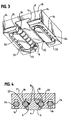
- Fig 3 is a perspective view of the bottom and end of car 2 disengaged from track 4.
- Ball bearings 16 rotate about races 20, which comprise straight open portion 22 and a continuous recirculating portion 24.
- Race recirculating portion 24 is preferably open to the bottom of car 2 for purposes of bearing 16 lubrication, inspection, and maintenance. It is noted that race recirculating portion 24 and open portion 22 are illustrated having a generally oval shape in Fig. 3; other shapes may be comprised, however, as particular applications may call for. Further, it is likewise noted that race open portion 22 need not be straight, other embodiments may comprise race open portions that are curved, for example.
- balls 16 are retained in race straight open portion 22 when car 2 is disengaged from the track by retaining clip 8.
- Car end wall 10 has locking holes 14 for receiving retaining clip 8 ends to thereby removably secure clip 8 in place. Clip 8 is guided by passing through car end wall guide slots 15 for support.
- Fig. 4 shows a cross section of car 2 on track 4.
- Ball bearings 16 are engaged between V-shaped groove 6 and race straight open portions 22. Bearings 16 are retained in race straight open portions 22 by retaining clips 8. Bearings 16 pass to and from race straight open portion 22 through recirculating portion 24.
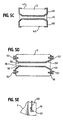
- Fig. 5A is a bottom partial cross sectional view of car 2, further showing bearings 16 rotating about race straight open portion 22 and recirculating portion 24.
- Clip 8 retains bearings 16 in straight open portion 22.
- Endwalls 10 of car 2 are substantially identical.
- the broken lines of Fig. 5A show the outline of race recirculating portion 24, as well as outlines of clip locking holes 14.
- Fig. 5B shows a first embodiment of retaining clip 8, as is illustrated generally in Fig. 5A, in greater detail.
- Clip 8 is preferably comprised of resilient metal, and may be comprised of, for example, wire. Other materials of construction may comprise resilient plastics.
- Clip 8 has a general U-shape, and has fingers 40 angled approximately 90° degrees for placing in locking holes 14 of car endwall 10 to secure clip 8 in place, as shown in Fig. 5A.
- Figs. 5C, 5D, and 5E illustrate other embodiments of the clip and the locking means of the invention.
- a retaining clip 40 wraps around car endwall 10 to extend over a portion of car sidewall 42.
- FIG. 5D illustrates retaining clip 50 being removably attached to car 2 by use of locking screws 52 screwed into car endwalls 10.
- Clip 50 may be wrapped about screw 52, or hooked around screw 52, or held by friction as screw 52 is tightened down on it.
- Fig. 5E shows a partial perspective view of a retaining clip 60 secured to car 2 by wrapping around locking boss 62 on car end wall 10.
- Locking boss 62 may comprise an integral part of car 2, or may comprise a pin, plug, or the like that is inserted into a receiving hole on wall 10. Such two piece construction may provide reduced manufacturing effort and cost. It is further noted that combinations of the various retaining clip attachment means and methods as illustrated in Figs.
- 5A, 5B, 5C, 5D, and 5E are contemplated; locking screws, bosses, or locking holes, for instance, could be used to fasten retaining clip 40 of Fig. 5C to car sidewall 42.
- the various clip embodiments of the invention may likewise be comprised of resilient plastic materials, of metal strapping, or of other suitable materials.
- Fig. 6A illustrates a perspective view of a second embodiment of a car 100 of the invention.
- car 100 further comprises projecting lugs 102 and 103 for receiving and removably holding retaining pin 104 in place to retain bearings 16 within race open portion 22.
- Retaining pin 104 in this embodiment comprises a generally straight member, which may be comprised of metal or plastic.
- Lugs 102 and 103 each have a hole for receiving an end of retaining pin 104, which may be deflected for insertion into the holes. Or, as illustrated in Figs.
- lug 102 may comprise a passage 105 for passing pin 104 through, with the first end of pin 104 received and seated in the hole of opposite lug 103. After insertion of pin 104, threaded plug 106 is threaded or otherwise secured in passage 105 to thereby lock pin 104 in place. Since it is not required to be deflected for insertion or removal of bearings, pin 104 in this embodiment may be comprised of substantially stiff, unbending material.
- Fig. 7 is an end view of car 100 on track 110.
- Track 110 has converging walls 112 for engaging bearings 16, with elongated slot 114 at their convergence for movably receiving retaining pin 104 of Fig. 6 and projecting lugs 102 and 103.
- Fig. 8A illustrates a bottom perspective view of still another embodiment of the traveler of the invention.
- car 150 is as generally described herein, except that it comprises removable end plates 152 and 154 which are removably held in place at car ends with locking screws 156 that pass through plate passages 158 to be threadably received by car 150.
- Fig. 8B is a partially exploded bottom perspective of car 150 with one end plate 152 and set of screws 156 removed from car 150. Threaded receiving holes 157 are shown in car 150 for receiving screws 156.
- Retaining pin 162 for retaining ball bearings 164 in race open portion 166 is received by holes 168 in tugs 170 on endplates 152.
- pin 162 may be fixedly attached to one or the other of end plates 152 to be received by the respective other of said end plates 152.
- Fig 8C shows a perspective view of an end plate 152.
- end plate 152 preferably comprises the outer wall of rounded race end portion 172. This preferred construction allows for reduced machining costs for car 150.
- Fig. 8C further illustrates passages 158 and lugs 170 with pin receiving holes 168. It is noted that other embodiments of end plates 152 may not comprise a portion of the car race, and may instead comprise end plates operable for removably holding pin 162 in place.
- still another embodiment of the car of the invention may comprise retaining means that are integral with the car.
- This embodiment may comprise a retaining bridge spanning the race open portion which appears and operates in the same general manner as described above for the retaining clips or pins of the invention.
Landscapes
- Engineering & Computer Science (AREA)
- General Engineering & Computer Science (AREA)
- Mechanical Engineering (AREA)
- Life Sciences & Earth Sciences (AREA)
- Sustainable Development (AREA)
- Sustainable Energy (AREA)
- Chemical & Material Sciences (AREA)
- Combustion & Propulsion (AREA)
- Ocean & Marine Engineering (AREA)
- Hooks, Suction Cups, And Attachment By Adhesive Means (AREA)
- Rolling Contact Bearings (AREA)
- Bearings For Parts Moving Linearly (AREA)
Applications Claiming Priority (2)
| Application Number | Priority Date | Filing Date | Title |
|---|---|---|---|
| US352432 | 1999-07-13 | ||
| US09/352,432 US6158373A (en) | 1999-07-13 | 1999-07-13 | Traveler car with recirculating ball bearings and bearing retainer |
Publications (3)
| Publication Number | Publication Date |
|---|---|
| EP1069042A2 true EP1069042A2 (fr) | 2001-01-17 |
| EP1069042A3 EP1069042A3 (fr) | 2002-09-25 |
| EP1069042B1 EP1069042B1 (fr) | 2005-09-21 |
Family
ID=23385114
Family Applications (1)
| Application Number | Title | Priority Date | Filing Date |
|---|---|---|---|
| EP00114374A Expired - Lifetime EP1069042B1 (fr) | 1999-07-13 | 2000-07-05 | Chariot mobile avec palier à recirculation des billes et avec cage à billes |
Country Status (6)
| Country | Link |
|---|---|
| US (1) | US6158373A (fr) |
| EP (1) | EP1069042B1 (fr) |
| AT (1) | ATE304970T1 (fr) |
| AU (1) | AU4509600A (fr) |
| DE (1) | DE60022706T2 (fr) |
| NZ (1) | NZ505552A (fr) |
Cited By (2)
| Publication number | Priority date | Publication date | Assignee | Title |
|---|---|---|---|---|
| EP1338812A3 (fr) * | 2002-02-26 | 2004-08-18 | Nippon Thompson Co., Ltd. | Unité de guidage linéaire |
| EP1524183A1 (fr) * | 2004-01-23 | 2005-04-20 | OPAC S.r.l. | Système modulaire de support de mouvement pour un toit de vehicle ouvrant, en particulier pour un bateau |
Families Citing this family (8)
| Publication number | Priority date | Publication date | Assignee | Title |
|---|---|---|---|---|
| AU2003200130B2 (en) * | 2002-02-01 | 2008-06-26 | Even Keel Pty Ltd | A bearing assembly |
| AUPS028002A0 (en) * | 2002-02-01 | 2002-02-28 | Ausman Engineering And Associates Pty Ltd | A bearing assembly |
| DE102006027215B4 (de) * | 2006-06-12 | 2008-03-27 | Hiwin Technologies Corp. | Abstandshalter für eine Linearführung |
| JP6201344B2 (ja) * | 2012-03-27 | 2017-09-27 | Thk株式会社 | 運動装置 |
| JP5695248B2 (ja) * | 2013-04-10 | 2015-04-01 | Thk株式会社 | 運動案内装置 |
| WO2019013748A1 (fr) | 2017-07-10 | 2019-01-17 | Hewlett-Packard Development Company, L.P. | Chariots à billes |
| ES1283122Y (es) | 2021-08-31 | 2022-02-24 | Thiha Kyaw Thi Win | Dispositivo deslizante |
| IT202200021492A1 (it) * | 2022-10-18 | 2024-04-18 | Federico Calistri | Porta per imbarcazioni |
Citations (1)
| Publication number | Priority date | Publication date | Assignee | Title |
|---|---|---|---|---|
| US4144830A (en) | 1977-11-18 | 1979-03-20 | Nicro Corporation | Low friction track traveler |
Family Cites Families (15)
| Publication number | Priority date | Publication date | Assignee | Title |
|---|---|---|---|---|
| GB979339A (en) * | 1962-12-27 | 1965-01-01 | Ian Proctor Metal Masts Ltd | Improvements in or relating to traveller systems |
| IT1139218B (it) * | 1981-10-15 | 1986-09-24 | Lomazzo Costr Mecc | Passascotte a rulli per la manovra delle vele nelle bauche |
| JPS58155426U (ja) * | 1982-04-14 | 1983-10-17 | 日本精工株式会社 | 軌道案内軸受 |
| US4582369A (en) * | 1982-09-24 | 1986-04-15 | Tsubakimoto Precision Products Co., Ltd. | Linear motion ball bearing |
| US4630562A (en) * | 1983-05-02 | 1986-12-23 | Atecs Corporation | Adjustable mast step |
| JPS60196428A (ja) * | 1984-03-19 | 1985-10-04 | Hiroshi Teramachi | ベアリングユニツト |
| US4557530A (en) * | 1984-05-24 | 1985-12-10 | Haase Harold A | Flat, compact, linear ball bearing with wedge-locked eccentric adjustment and removable races in cylindrical seats |
| US4719869A (en) * | 1986-11-06 | 1988-01-19 | Vanguard, Inc. | Sailboat traveler car assembly with removable block |
| US4823720A (en) * | 1987-07-24 | 1989-04-25 | Foster Lewis R | Batten attachment |
| JP2819610B2 (ja) * | 1989-05-01 | 1998-10-30 | 日本精工株式会社 | ボール・ころ併用リニアガイド装置 |
| US4932067A (en) * | 1989-05-30 | 1990-06-05 | Thomson Industries, Inc. | Linear motion bearing |
| US5127351A (en) * | 1991-01-16 | 1992-07-07 | Breems Martinus V | Batten end fitting |
| US5149059A (en) * | 1991-04-25 | 1992-09-22 | Harken, Inc. | Low profile multiple bearing block fairlead |
| DK0643658T3 (da) * | 1992-06-12 | 1996-11-04 | Gert Hans Frederiksen | Skinnesystem |
| JP3547207B2 (ja) * | 1995-02-23 | 2004-07-28 | 日本トムソン株式会社 | 直動転がり案内ユニット |
-
1999
- 1999-07-13 US US09/352,432 patent/US6158373A/en not_active Expired - Lifetime
-
2000
- 2000-07-05 NZ NZ505552A patent/NZ505552A/en not_active IP Right Cessation
- 2000-07-05 DE DE60022706T patent/DE60022706T2/de not_active Expired - Lifetime
- 2000-07-05 AT AT00114374T patent/ATE304970T1/de not_active IP Right Cessation
- 2000-07-05 EP EP00114374A patent/EP1069042B1/fr not_active Expired - Lifetime
- 2000-07-06 AU AU45096/00A patent/AU4509600A/en not_active Abandoned
Patent Citations (1)
| Publication number | Priority date | Publication date | Assignee | Title |
|---|---|---|---|---|
| US4144830A (en) | 1977-11-18 | 1979-03-20 | Nicro Corporation | Low friction track traveler |
Cited By (4)
| Publication number | Priority date | Publication date | Assignee | Title |
|---|---|---|---|---|
| EP1338812A3 (fr) * | 2002-02-26 | 2004-08-18 | Nippon Thompson Co., Ltd. | Unité de guidage linéaire |
| US6880975B2 (en) | 2002-02-26 | 2005-04-19 | Nippon Thompson Co., Ltd. | Linear motion guide unit |
| EP1524183A1 (fr) * | 2004-01-23 | 2005-04-20 | OPAC S.r.l. | Système modulaire de support de mouvement pour un toit de vehicle ouvrant, en particulier pour un bateau |
| US7055453B2 (en) | 2004-01-23 | 2006-06-06 | Opac S.R.L. | Modular movement support system for an openable roof for a vehicle, in particular for a boat |
Also Published As
| Publication number | Publication date |
|---|---|
| AU4509600A (en) | 2001-03-08 |
| DE60022706T2 (de) | 2006-07-06 |
| ATE304970T1 (de) | 2005-10-15 |
| DE60022706D1 (de) | 2006-02-02 |
| EP1069042B1 (fr) | 2005-09-21 |
| US6158373A (en) | 2000-12-12 |
| EP1069042A3 (fr) | 2002-09-25 |
| NZ505552A (en) | 2002-04-26 |
Similar Documents
| Publication | Publication Date | Title |
|---|---|---|
| US6158373A (en) | Traveler car with recirculating ball bearings and bearing retainer | |
| US7673851B2 (en) | Block with improved central mounting | |
| US4723499A (en) | Furling system for sailboats | |
| DE69711407T2 (de) | Antrieb für eine winde | |
| AU2004235657B2 (en) | Traveler car with recirculating ball bearings and bearing retainer | |
| EP0108531A1 (fr) | Dispositif pour enfiler | |
| US4719869A (en) | Sailboat traveler car assembly with removable block | |
| US4473024A (en) | Self-locking covering device for standing rigging | |
| US5538223A (en) | Single line multiple purchase block and tackle system | |
| US4584945A (en) | Load-transfer device and system | |
| US5065686A (en) | Sail batten compression adjustment fitting | |
| US4473021A (en) | Spinnaker boom | |
| AU766212B2 (en) | Swivel post latch system for bearing block | |
| US4340005A (en) | Luff feeder assembly for grooved jibstay foils | |
| US4651668A (en) | Traveller control for sailcraft | |
| EP4140873A1 (fr) | Dispositif coulissant | |
| US4319537A (en) | Sailcraft traveler car and assembly | |
| US4474132A (en) | Pennant support | |
| GB2328664A (en) | Safety rail traveller | |
| WO1993009999A1 (fr) | Chariot mobile utilisable lors du bordage de la voile ou de la voilure d'un bateau a voiles | |
| US4206716A (en) | Clamping roller assembly | |
| GB2322674A (en) | Traveller car | |
| US4557212A (en) | Bearing systems for sailcraft gooseneck units | |
| US4807550A (en) | Belaying clamp | |
| EP0078350A1 (fr) | Dispositif pour emmagasiner et pour attacher des voiles aux mâts ou étais |
Legal Events
| Date | Code | Title | Description |
|---|---|---|---|
| PUAI | Public reference made under article 153(3) epc to a published international application that has entered the european phase |
Free format text: ORIGINAL CODE: 0009012 |
|
| AK | Designated contracting states |
Kind code of ref document: A2 Designated state(s): AT BE CH CY DE DK ES FI FR GB GR IE IT LI LU MC NL PT SE |
|
| AX | Request for extension of the european patent |
Free format text: AL;LT;LV;MK;RO;SI |
|
| PUAL | Search report despatched |
Free format text: ORIGINAL CODE: 0009013 |
|
| AK | Designated contracting states |
Kind code of ref document: A3 Designated state(s): AT BE CH CY DE DK ES FI FR GB GR IE IT LI LU MC NL PT SE |
|
| AX | Request for extension of the european patent |
Free format text: AL;LT;LV;MK;RO;SI |
|
| 17P | Request for examination filed |
Effective date: 20030320 |
|
| AKX | Designation fees paid |
Designated state(s): AT BE CH CY DE DK ES FI FR GB GR IE IT LI LU MC NL PT SE |
|
| 17Q | First examination report despatched |
Effective date: 20030513 |
|
| GRAP | Despatch of communication of intention to grant a patent |
Free format text: ORIGINAL CODE: EPIDOSNIGR1 |
|
| GRAS | Grant fee paid |
Free format text: ORIGINAL CODE: EPIDOSNIGR3 |
|
| GRAA | (expected) grant |
Free format text: ORIGINAL CODE: 0009210 |
|
| AK | Designated contracting states |
Kind code of ref document: B1 Designated state(s): AT BE CH CY DE DK ES FI FR GB GR IE IT LI LU MC NL PT SE |
|
| PG25 | Lapsed in a contracting state [announced via postgrant information from national office to epo] |
Ref country code: AT Free format text: LAPSE BECAUSE OF FAILURE TO SUBMIT A TRANSLATION OF THE DESCRIPTION OR TO PAY THE FEE WITHIN THE PRESCRIBED TIME-LIMIT Effective date: 20050921 Ref country code: NL Free format text: LAPSE BECAUSE OF FAILURE TO SUBMIT A TRANSLATION OF THE DESCRIPTION OR TO PAY THE FEE WITHIN THE PRESCRIBED TIME-LIMIT Effective date: 20050921 Ref country code: BE Free format text: LAPSE BECAUSE OF FAILURE TO SUBMIT A TRANSLATION OF THE DESCRIPTION OR TO PAY THE FEE WITHIN THE PRESCRIBED TIME-LIMIT Effective date: 20050921 Ref country code: LI Free format text: LAPSE BECAUSE OF FAILURE TO SUBMIT A TRANSLATION OF THE DESCRIPTION OR TO PAY THE FEE WITHIN THE PRESCRIBED TIME-LIMIT Effective date: 20050921 Ref country code: CH Free format text: LAPSE BECAUSE OF FAILURE TO SUBMIT A TRANSLATION OF THE DESCRIPTION OR TO PAY THE FEE WITHIN THE PRESCRIBED TIME-LIMIT Effective date: 20050921 Ref country code: FI Free format text: LAPSE BECAUSE OF FAILURE TO SUBMIT A TRANSLATION OF THE DESCRIPTION OR TO PAY THE FEE WITHIN THE PRESCRIBED TIME-LIMIT Effective date: 20050921 |
|
| REG | Reference to a national code |
Ref country code: GB Ref legal event code: FG4D |
|
| REG | Reference to a national code |
Ref country code: CH Ref legal event code: EP |
|
| REG | Reference to a national code |
Ref country code: IE Ref legal event code: FG4D |
|
| REF | Corresponds to: |
Ref document number: 60022706 Country of ref document: DE Date of ref document: 20051027 Kind code of ref document: P |
|
| PG25 | Lapsed in a contracting state [announced via postgrant information from national office to epo] |
Ref country code: GR Free format text: LAPSE BECAUSE OF FAILURE TO SUBMIT A TRANSLATION OF THE DESCRIPTION OR TO PAY THE FEE WITHIN THE PRESCRIBED TIME-LIMIT Effective date: 20051221 Ref country code: SE Free format text: LAPSE BECAUSE OF FAILURE TO SUBMIT A TRANSLATION OF THE DESCRIPTION OR TO PAY THE FEE WITHIN THE PRESCRIBED TIME-LIMIT Effective date: 20051221 Ref country code: DK Free format text: LAPSE BECAUSE OF FAILURE TO SUBMIT A TRANSLATION OF THE DESCRIPTION OR TO PAY THE FEE WITHIN THE PRESCRIBED TIME-LIMIT Effective date: 20051221 |
|
| PG25 | Lapsed in a contracting state [announced via postgrant information from national office to epo] |
Ref country code: ES Free format text: LAPSE BECAUSE OF FAILURE TO SUBMIT A TRANSLATION OF THE DESCRIPTION OR TO PAY THE FEE WITHIN THE PRESCRIBED TIME-LIMIT Effective date: 20060101 |
|
| REF | Corresponds to: |
Ref document number: 60022706 Country of ref document: DE Date of ref document: 20060202 Kind code of ref document: P |
|
| PG25 | Lapsed in a contracting state [announced via postgrant information from national office to epo] |
Ref country code: PT Free format text: LAPSE BECAUSE OF FAILURE TO SUBMIT A TRANSLATION OF THE DESCRIPTION OR TO PAY THE FEE WITHIN THE PRESCRIBED TIME-LIMIT Effective date: 20060221 |
|
| NLV1 | Nl: lapsed or annulled due to failure to fulfill the requirements of art. 29p and 29m of the patents act | ||
| REG | Reference to a national code |
Ref country code: CH Ref legal event code: PL |
|
| ET | Fr: translation filed | ||
| PG25 | Lapsed in a contracting state [announced via postgrant information from national office to epo] |
Ref country code: IE Free format text: LAPSE BECAUSE OF NON-PAYMENT OF DUE FEES Effective date: 20060705 |
|
| PLBE | No opposition filed within time limit |
Free format text: ORIGINAL CODE: 0009261 |
|
| STAA | Information on the status of an ep patent application or granted ep patent |
Free format text: STATUS: NO OPPOSITION FILED WITHIN TIME LIMIT |
|
| PG25 | Lapsed in a contracting state [announced via postgrant information from national office to epo] |
Ref country code: MC Free format text: LAPSE BECAUSE OF NON-PAYMENT OF DUE FEES Effective date: 20060731 |
|
| 26N | No opposition filed |
Effective date: 20060622 |
|
| REG | Reference to a national code |
Ref country code: IE Ref legal event code: MM4A |
|
| PG25 | Lapsed in a contracting state [announced via postgrant information from national office to epo] |
Ref country code: LU Free format text: LAPSE BECAUSE OF NON-PAYMENT OF DUE FEES Effective date: 20060705 |
|
| PG25 | Lapsed in a contracting state [announced via postgrant information from national office to epo] |
Ref country code: CY Free format text: LAPSE BECAUSE OF FAILURE TO SUBMIT A TRANSLATION OF THE DESCRIPTION OR TO PAY THE FEE WITHIN THE PRESCRIBED TIME-LIMIT Effective date: 20050921 |
|
| REG | Reference to a national code |
Ref country code: FR Ref legal event code: PLFP Year of fee payment: 17 |
|
| PGFP | Annual fee paid to national office [announced via postgrant information from national office to epo] |
Ref country code: DE Payment date: 20160726 Year of fee payment: 17 |
|
| REG | Reference to a national code |
Ref country code: FR Ref legal event code: PLFP Year of fee payment: 18 |
|
| REG | Reference to a national code |
Ref country code: DE Ref legal event code: R119 Ref document number: 60022706 Country of ref document: DE |
|
| PG25 | Lapsed in a contracting state [announced via postgrant information from national office to epo] |
Ref country code: DE Free format text: LAPSE BECAUSE OF NON-PAYMENT OF DUE FEES Effective date: 20180201 |
|
| REG | Reference to a national code |
Ref country code: FR Ref legal event code: PLFP Year of fee payment: 19 |
|
| PGFP | Annual fee paid to national office [announced via postgrant information from national office to epo] |
Ref country code: GB Payment date: 20180727 Year of fee payment: 19 |
|
| PGFP | Annual fee paid to national office [announced via postgrant information from national office to epo] |
Ref country code: FR Payment date: 20190725 Year of fee payment: 20 Ref country code: IT Payment date: 20190726 Year of fee payment: 20 |
|
| GBPC | Gb: european patent ceased through non-payment of renewal fee |
Effective date: 20190705 |
|
| PG25 | Lapsed in a contracting state [announced via postgrant information from national office to epo] |
Ref country code: GB Free format text: LAPSE BECAUSE OF NON-PAYMENT OF DUE FEES Effective date: 20190705 |