EP1068433B1 - Moteur a combustion interne a allumage commande et a injection directe - Google Patents
Moteur a combustion interne a allumage commande et a injection directe Download PDFInfo
- Publication number
- EP1068433B1 EP1068433B1 EP99913368A EP99913368A EP1068433B1 EP 1068433 B1 EP1068433 B1 EP 1068433B1 EP 99913368 A EP99913368 A EP 99913368A EP 99913368 A EP99913368 A EP 99913368A EP 1068433 B1 EP1068433 B1 EP 1068433B1
- Authority
- EP
- European Patent Office
- Prior art keywords
- cylinder
- recess
- injector
- engine
- axis
- Prior art date
- Legal status (The legal status is an assumption and is not a legal conclusion. Google has not performed a legal analysis and makes no representation as to the accuracy of the status listed.)
- Expired - Lifetime
Links
- 238000002485 combustion reaction Methods 0.000 title claims description 11
- 238000002347 injection Methods 0.000 title claims description 11
- 239000007924 injection Substances 0.000 title claims description 11
- 239000000446 fuel Substances 0.000 claims description 47
- 239000007789 gas Substances 0.000 claims description 20
- 230000000694 effects Effects 0.000 claims description 3
- 238000005422 blasting Methods 0.000 claims 1
- 230000000295 complement effect Effects 0.000 claims 1
- 239000000203 mixture Substances 0.000 description 9
- 239000000243 solution Substances 0.000 description 9
- 238000013517 stratification Methods 0.000 description 5
- 230000006835 compression Effects 0.000 description 3
- 238000007906 compression Methods 0.000 description 3
- IJGRMHOSHXDMSA-UHFFFAOYSA-N Atomic nitrogen Chemical compound N#N IJGRMHOSHXDMSA-UHFFFAOYSA-N 0.000 description 2
- 238000009825 accumulation Methods 0.000 description 1
- 238000013459 approach Methods 0.000 description 1
- 210000004027 cell Anatomy 0.000 description 1
- 238000004891 communication Methods 0.000 description 1
- 238000009833 condensation Methods 0.000 description 1
- 230000005494 condensation Effects 0.000 description 1
- 238000001816 cooling Methods 0.000 description 1
- 230000001419 dependent effect Effects 0.000 description 1
- 239000008240 homogeneous mixture Substances 0.000 description 1
- 238000002513 implantation Methods 0.000 description 1
- 238000004519 manufacturing process Methods 0.000 description 1
- 238000000034 method Methods 0.000 description 1
- 230000007935 neutral effect Effects 0.000 description 1
- 229910052757 nitrogen Inorganic materials 0.000 description 1
- 230000035515 penetration Effects 0.000 description 1
- 230000002093 peripheral effect Effects 0.000 description 1
- 230000037452 priming Effects 0.000 description 1
- 238000005507 spraying Methods 0.000 description 1
- 239000000126 substance Substances 0.000 description 1
- 238000013519 translation Methods 0.000 description 1
Images


Classifications
-
- F—MECHANICAL ENGINEERING; LIGHTING; HEATING; WEAPONS; BLASTING
- F02—COMBUSTION ENGINES; HOT-GAS OR COMBUSTION-PRODUCT ENGINE PLANTS
- F02B—INTERNAL-COMBUSTION PISTON ENGINES; COMBUSTION ENGINES IN GENERAL
- F02B23/00—Other engines characterised by special shape or construction of combustion chambers to improve operation
- F02B23/08—Other engines characterised by special shape or construction of combustion chambers to improve operation with positive ignition
- F02B23/10—Other engines characterised by special shape or construction of combustion chambers to improve operation with positive ignition with separate admission of air and fuel into cylinder
-
- F—MECHANICAL ENGINEERING; LIGHTING; HEATING; WEAPONS; BLASTING
- F02—COMBUSTION ENGINES; HOT-GAS OR COMBUSTION-PRODUCT ENGINE PLANTS
- F02F—CYLINDERS, PISTONS OR CASINGS, FOR COMBUSTION ENGINES; ARRANGEMENTS OF SEALINGS IN COMBUSTION ENGINES
- F02F1/00—Cylinders; Cylinder heads
- F02F1/24—Cylinder heads
- F02F1/42—Shape or arrangement of intake or exhaust channels in cylinder heads
- F02F1/4214—Shape or arrangement of intake or exhaust channels in cylinder heads specially adapted for four or more valves per cylinder
-
- F—MECHANICAL ENGINEERING; LIGHTING; HEATING; WEAPONS; BLASTING
- F02—COMBUSTION ENGINES; HOT-GAS OR COMBUSTION-PRODUCT ENGINE PLANTS
- F02B—INTERNAL-COMBUSTION PISTON ENGINES; COMBUSTION ENGINES IN GENERAL
- F02B17/00—Engines characterised by means for effecting stratification of charge in cylinders
- F02B17/005—Engines characterised by means for effecting stratification of charge in cylinders having direct injection in the combustion chamber
-
- F—MECHANICAL ENGINEERING; LIGHTING; HEATING; WEAPONS; BLASTING
- F02—COMBUSTION ENGINES; HOT-GAS OR COMBUSTION-PRODUCT ENGINE PLANTS
- F02B—INTERNAL-COMBUSTION PISTON ENGINES; COMBUSTION ENGINES IN GENERAL
- F02B23/00—Other engines characterised by special shape or construction of combustion chambers to improve operation
- F02B23/08—Other engines characterised by special shape or construction of combustion chambers to improve operation with positive ignition
- F02B23/10—Other engines characterised by special shape or construction of combustion chambers to improve operation with positive ignition with separate admission of air and fuel into cylinder
- F02B23/101—Other engines characterised by special shape or construction of combustion chambers to improve operation with positive ignition with separate admission of air and fuel into cylinder the injector being placed on or close to the cylinder centre axis, e.g. with mixture formation using spray guided concepts
-
- F—MECHANICAL ENGINEERING; LIGHTING; HEATING; WEAPONS; BLASTING
- F02—COMBUSTION ENGINES; HOT-GAS OR COMBUSTION-PRODUCT ENGINE PLANTS
- F02B—INTERNAL-COMBUSTION PISTON ENGINES; COMBUSTION ENGINES IN GENERAL
- F02B23/00—Other engines characterised by special shape or construction of combustion chambers to improve operation
- F02B23/08—Other engines characterised by special shape or construction of combustion chambers to improve operation with positive ignition
- F02B23/10—Other engines characterised by special shape or construction of combustion chambers to improve operation with positive ignition with separate admission of air and fuel into cylinder
- F02B23/104—Other engines characterised by special shape or construction of combustion chambers to improve operation with positive ignition with separate admission of air and fuel into cylinder the injector being placed on a side position of the cylinder
-
- F—MECHANICAL ENGINEERING; LIGHTING; HEATING; WEAPONS; BLASTING
- F02—COMBUSTION ENGINES; HOT-GAS OR COMBUSTION-PRODUCT ENGINE PLANTS
- F02B—INTERNAL-COMBUSTION PISTON ENGINES; COMBUSTION ENGINES IN GENERAL
- F02B31/00—Modifying induction systems for imparting a rotation to the charge in the cylinder
- F02B31/08—Modifying induction systems for imparting a rotation to the charge in the cylinder having multiple air inlets
- F02B31/085—Modifying induction systems for imparting a rotation to the charge in the cylinder having multiple air inlets having two inlet valves
-
- F—MECHANICAL ENGINEERING; LIGHTING; HEATING; WEAPONS; BLASTING
- F02—COMBUSTION ENGINES; HOT-GAS OR COMBUSTION-PRODUCT ENGINE PLANTS
- F02B—INTERNAL-COMBUSTION PISTON ENGINES; COMBUSTION ENGINES IN GENERAL
- F02B23/00—Other engines characterised by special shape or construction of combustion chambers to improve operation
- F02B23/08—Other engines characterised by special shape or construction of combustion chambers to improve operation with positive ignition
- F02B23/10—Other engines characterised by special shape or construction of combustion chambers to improve operation with positive ignition with separate admission of air and fuel into cylinder
- F02B2023/106—Tumble flow, i.e. the axis of rotation of the main charge flow motion is horizontal
-
- F—MECHANICAL ENGINEERING; LIGHTING; HEATING; WEAPONS; BLASTING
- F02—COMBUSTION ENGINES; HOT-GAS OR COMBUSTION-PRODUCT ENGINE PLANTS
- F02B—INTERNAL-COMBUSTION PISTON ENGINES; COMBUSTION ENGINES IN GENERAL
- F02B23/00—Other engines characterised by special shape or construction of combustion chambers to improve operation
- F02B23/08—Other engines characterised by special shape or construction of combustion chambers to improve operation with positive ignition
- F02B23/10—Other engines characterised by special shape or construction of combustion chambers to improve operation with positive ignition with separate admission of air and fuel into cylinder
- F02B2023/106—Tumble flow, i.e. the axis of rotation of the main charge flow motion is horizontal
- F02B2023/107—Reverse tumble flow, e.g. having substantially vertical intake ports
-
- F—MECHANICAL ENGINEERING; LIGHTING; HEATING; WEAPONS; BLASTING
- F02—COMBUSTION ENGINES; HOT-GAS OR COMBUSTION-PRODUCT ENGINE PLANTS
- F02B—INTERNAL-COMBUSTION PISTON ENGINES; COMBUSTION ENGINES IN GENERAL
- F02B75/00—Other engines
- F02B75/12—Other methods of operation
- F02B2075/125—Direct injection in the combustion chamber for spark ignition engines, i.e. not in pre-combustion chamber
-
- F—MECHANICAL ENGINEERING; LIGHTING; HEATING; WEAPONS; BLASTING
- F02—COMBUSTION ENGINES; HOT-GAS OR COMBUSTION-PRODUCT ENGINE PLANTS
- F02B—INTERNAL-COMBUSTION PISTON ENGINES; COMBUSTION ENGINES IN GENERAL
- F02B2275/00—Other engines, components or details, not provided for in other groups of this subclass
- F02B2275/48—Tumble motion in gas movement in cylinder
-
- F—MECHANICAL ENGINEERING; LIGHTING; HEATING; WEAPONS; BLASTING
- F02—COMBUSTION ENGINES; HOT-GAS OR COMBUSTION-PRODUCT ENGINE PLANTS
- F02F—CYLINDERS, PISTONS OR CASINGS, FOR COMBUSTION ENGINES; ARRANGEMENTS OF SEALINGS IN COMBUSTION ENGINES
- F02F1/00—Cylinders; Cylinder heads
- F02F1/24—Cylinder heads
- F02F2001/244—Arrangement of valve stems in cylinder heads
- F02F2001/245—Arrangement of valve stems in cylinder heads the valve stems being orientated at an angle with the cylinder axis
-
- F—MECHANICAL ENGINEERING; LIGHTING; HEATING; WEAPONS; BLASTING
- F02—COMBUSTION ENGINES; HOT-GAS OR COMBUSTION-PRODUCT ENGINE PLANTS
- F02F—CYLINDERS, PISTONS OR CASINGS, FOR COMBUSTION ENGINES; ARRANGEMENTS OF SEALINGS IN COMBUSTION ENGINES
- F02F3/00—Pistons
- F02F3/26—Pistons having combustion chamber in piston head
-
- Y—GENERAL TAGGING OF NEW TECHNOLOGICAL DEVELOPMENTS; GENERAL TAGGING OF CROSS-SECTIONAL TECHNOLOGIES SPANNING OVER SEVERAL SECTIONS OF THE IPC; TECHNICAL SUBJECTS COVERED BY FORMER USPC CROSS-REFERENCE ART COLLECTIONS [XRACs] AND DIGESTS
- Y02—TECHNOLOGIES OR APPLICATIONS FOR MITIGATION OR ADAPTATION AGAINST CLIMATE CHANGE
- Y02T—CLIMATE CHANGE MITIGATION TECHNOLOGIES RELATED TO TRANSPORTATION
- Y02T10/00—Road transport of goods or passengers
- Y02T10/10—Internal combustion engine [ICE] based vehicles
- Y02T10/12—Improving ICE efficiencies
Definitions
- the invention relates to an internal combustion engine with controlled ignition and direct injection.
- the invention relates more particularly to a motor with internal combustion with ignition and injection direct, of the type in which a cylinder is axially delimited upwards by a lower face of a cylinder head in which open out, each via a valve corresponding, at least one intake duct and at least an exhaust pipe, intake valves and exhaust being arranged respectively on the one hand and on the other side of a reference plane containing the axis of the cylinder and delimiting an intake side of an exhaust side of the cylinder.
- the excess air prevents part of the fuel remains unburnt after combustion and is discharged with exhaust gases.
- the fuel mixture that results from the injection of fuel in the cylinder can be a homogeneous mixture or a layered mixture in which the air / fuel ratio is not not constant throughout the cylinder. For example, we can seek a higher concentration of fuel in the vicinity of the spark plug to facilitate combustion start.
- a first consists in positioning the injector and the spark plug in such a way that the fuel jet is projected directly from the injector towards the spark plug.
- This method is a priori very efficient but it can be sensitive to the positioning uncertainties of the different elements and, even more, the possible fouling of the nose injector which can significantly modify the characteristics of the fuel jet.
- a second known solution consists in carrying out a wall effect stratification by directing the fuel jet towards a wall, for example the upper face of the piston, to then direct it towards the spark plug.
- a motor implementing this solution is for example described in document EP-A-0.558.072.
- significant condensation may occur fuel on the walls, the fuel thus condensed being so very hardly flammable.
- a third known solution consists in carrying out a stratification by producing a so-called "tumble" movement in the intake gases and position the injector so that direct the jet of fuel against the movement of gases intake.
- GB-A-2.310.003 describes an engine implementing this solution. This solution allows to improve the operation of the engine in a layered mixture. However, this solution still requires improvement, in particular to optimize the interception of jet of fuel by the inlet gas streams.
- the object of the invention is therefore to propose a solution overall in terms of geometry and location of elements essentials of an internal combustion and ignition engine controlled to achieve optimal operation of the engine with stratified "poor" loads.
- the invention proposes an engine such as that which is defined by claim 1.
- FIG. 1 Is illustrated in Figure 1 a cylinder 10 of a motor to internal combustion with ignition and injection direct.
- the cylinder 10, of axis A1 is delimited in an engine block 12 by a cylindrical wall 14.
- the cylinder 10 is bounded upwards by the underside 16 of a cylinder head 18 and, downwards, by the upper face 20 of a piston 22 which, from known manner, is animated by an alternating movement of translation along the axis A1.
- Two air intake ducts 24 are fitted in the cylinder head 18 so as to open into the lower face 16 thereof. Communication between conduits 24 and cylinder 10 is allowed or interrupted by controlled intake valves 26.
- exhaust pipes 28 open into cylinder 10 via exhaust valves 30.
- the underside 16 of cylinder head 18 is configured as a “roof” so that it has two sides 32, 34 which are substantially planes and inclines on either side of a summit ridge 36.
- the angle of the roof is for example between 125 and 145 degrees.
- the intake ducts 24 open into one 34 sections while the exhaust pipes 28 lead into the other 32 sections.
- the top edge 36 and the axis A1 of the cylinder 10 thus determine a reference plane which delimits in this cylinder one intake side and one exhaust side.
- a spark plug 38 is screwed into cylinder head 16 so so that its electrodes 40 open into the cylinder 10, substantially on the axis A1 thereof and therefore at the level of the top edge 36 of the underside 16 of the cylinder head 18.
- an injector 42 is installed in the cylinder head 18, between the intake ducts 24 or just in below these, so that a nose 44 of the injector 42 opens into cylinder 10 in order to project directly inside it a jet of fuel.
- the injector 42 projects a jet of fuel substantially conical, the axis of the fuel jet being substantially coincident with that A2 of the injector 42 which, as can be seen in figures 1 and 2, forms an angle ⁇ about 20 to 40 ° with a plane P perpendicular to the axis A1 of cylinder 10.
- the axis A2 of the injector 42 is contained in a plan which is that of figure 1, that is to say the plan perpendicular to the summit ridge 36.
- the cylinder 10 is provided with at least one intake duct 24 which comprises means to create, at least for certain phases of engine operation, a vortex movement called "Tumble" in cylinder 10.
- These means can be formed simply by the shape of the intake duct 24 but they can also be constituted by means additional interposed in the intake duct, mobile or fixed, and likely to disturb the flow of air in the conduit 24 so that, inside the cylinder 10, is creates a vortex flow which in the plane perpendicular to the top edge 36, rotates about an axis parallel to this edge 36, counterclockwise when we look at cylinder 10 so that the valves intake valves are on the right and the exhaust valves at left. This flow, given its sense of rotation, will be called “direct tumble” in the remainder of the text.
- the fuel jet tends to be intercepted by gas currents which cause a fuel accumulation in the vicinity of the electrodes 40 of candle 34.
- the movement of gas and fuel between them an angle of about 120 degrees.
- the orientation of the injector 42 by variation of the angle ⁇ , it is possible to vary the angle between the two movements so that the two movements oppose in greater or lesser measured.
- the stratification of the fuel mixture is obtained thanks to the aerodynamics of the gases in cylinder 10, due to interception of fuel by moving gases, in limiting the contact of fuel with the cylinder walls, that is to say by limiting the contacts with the upper face 20 of the piston 22 and with the side face 14 of the cylinder 10.
- fuel should be injected into the cylinder with not too much momentum important.
- the force of the injection must indeed be such the fuel can be diverted towards the spark plug 38 before coming into contact with piston 22.
- it will better to use an injector 42 with reduced penetration.
- the upper face 20 of the piston 22 has a concave recess 46 which allows to channel the vortex movement of "Tumble" of the gases contained in the cylinder, especially during compression time when the piston 22 goes up in the cylinder 10 to its top dead center position.
- This recess 46 may for example be of shape lenticular and be centered with respect to the axis A1 of the cylinder.
- this recess 46 will advantageously be offset with respect to the axis A1 of so as to be arranged substantially below the valves exhaust 30, as we can see more particularly in Figure 3.
- the recess 46 is thus delimited by an element of side wall 52 which extends near the axis A1, slightly on the exhaust side of the cylinder, and which has a steep slope so as to force the rotary movement of the gas admitted into the cylinder to go up towards the spark plug 38.
- the face upper 20 of the piston 22 also comprises, plumb of the summit ridge 36, a boss 48 which makes it possible to limit the residual volume of the cylinder when the piston 22 is at the point dead high, in order to obtain an adequate compression ratio gases.
- the jet of fuel projected by the injector 42 is directed substantially in direction of the concave recess 46 in order to be able to interact with the vortex movement which is channeled by this recess. This is all the more important since, when we wishes to achieve a strong stratification of the air-fuel mixture, fuel injection is carried out relatively late in compression time, that is, when the piston 22 approaches its top dead center position.
- the fuel jet reaches the recess 46, which is arranged opposite the injector 42 in the cylinder 10, without hitting the upper face 20 of the piston 22, provision has been made to provide the recess 46 with a channel-shaped extension 50 which extends substantially in the direction of the fuel jet projected by the injector 42, in the direction of that.
- the dimensions and the depth of this channel, hollowed out between the boss 18 of the upper face 20, depend in particular on the geometry of the jet projected by the injector 42.
- this jet will be chosen so that the projection cone has an angle at the summit appreciably between 30 and 70 degrees.
- the boss 48 is arranged so as not to cause hunting effect when the piston 22 comes to neutral high.
- FIGS. 4 and 5 two variants of embodiment of the invention in which an injector is used 42 which projects a jet of fuel whose axis A3 is offset angularly with respect to that A2 of the injector 42.
- This offset can, as in the example embodiment of the Figure 4, be made in a plane containing both the axis A1 of the cylinder and the axis A2 of the injector 42 or, as in the example of embodiment of FIG. 5, in a perpendicular plane to axis A1 of cylinder 10.
- the injector 42 is arranged "below" the intake ducts 24, or between them, so that the nose of the injector 42 opens into a peripheral part of the underside 16 of cylinder head 18, that is to say a part arranged radially outward with respect to the axis A1 of the cylinder.
- the injector 42 is installed so as to emerge near the summit ridge 36 and the axis A1 of the cylinder.
- the injector 42 is implanted in the cylinder head 18 so that the nozzle 44 of the injector opens near the edge top 36 but in the pan 34 intake side of the cylinder being oriented substantially perpendicular to the pan exhaust 32.
- the spark plug 38 is located on the pan 32 on the exhaust side of the cylinder 10 but close of the summit ridge 36 so that its electrodes 40 are close to the axis A1 of the cylinder.
- FIGS. 8 and 9 is a variant of the previous one in which the injector 42 and the spark plug 38 are located parallel to the axis A1 of the cylinder so as to each lead to the summit ridge 36 but by being offset each on one side of the axis A1 according to the edge direction 36.
- the invention therefore makes it possible to carry out efficient stratification of the fuel mixture only thanks to the internal aerodynamics of the cylinder by limiting the fuel contact with walls, gas movements and fuel being oriented relative to each other such so that the fuel is diverted and transported by the gases in candle direction.
Landscapes
- Engineering & Computer Science (AREA)
- Chemical & Material Sciences (AREA)
- Combustion & Propulsion (AREA)
- Mechanical Engineering (AREA)
- General Engineering & Computer Science (AREA)
- Combustion Methods Of Internal-Combustion Engines (AREA)
- Cylinder Crankcases Of Internal Combustion Engines (AREA)
- Electrical Control Of Air Or Fuel Supplied To Internal-Combustion Engine (AREA)
Description
- la figure 1 est une vue schématique et partielle en coupe axiale d'un moteur conforme aux enseignements de l'invention ;
- la figure 2 est une vue, de dessous selon l'axe du cylindre, de la face inférieure de la culasse du moteur de la figure 1 ;
- la figure 3 est une vue schématique en perspective illustrant la forme de la face supérieure du piston du moteur de la figure 1 ;
- les figures 4 et 5 sont des vues schématiques en coupe axiale illustrant deux variantes du mode de réalisation de la figure 1 ; et
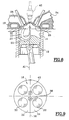
- les figures 6 et 7, 8 et 9 sont des vues similaires à celles des figures 1 et 2 qui illustrent respectivement quatre autres modes de réalisation d'un moteur selon l'invention.
Claims (6)
- Moteur à combustion interne à allumage commandé et à injection directe,
du type dans lequel un cylindre (10) est délimité axialement vers le haut par une face inférieure (16) d'une culasse (18) dans laquelle débouchent, chacun par l'intermédiaire d'une soupape (26, 30) correspondante, au moins un conduit d'admission (24) et au moins un conduit d'échappement (28), les soupapes d'admission (26) et d'échappement (30) étant agencées respectivement de part et d'autre d'un plan de référence (36) contenant l'axe (A1) du cylindre (10) et délimitant un côté admission d'un côté échappement du cylindre, du type dans lequel au moins un des conduits d'admission (24) est adapté pour créer dans le cylindre (10), au moins pour certaines phases de fonctionnement du moteur, un écoulement dit de "tumble" dans lequel les gaz contenus dans le cylindre sont animés d'un mouvement de rotation autour d'un axe perpendiculaire à l'axe (A1) du cylindre et parallèle au plan de référence, du type dans lequel un injecteur de carburant (42) est implanté de manière que le nez (44) de l'injecteur (42) débouche dans la face inférieure (16) de la culasse (18), et du type dans lequel le cylindre (10) est délimité axialement vers le bas par un piston (22) dont une face supérieure (20) comporte un évidement (46), l'évidement (46) et le nez (44) de l'injecteur (42) étant excentrés par rapport au plan de référence (36),
caractérisé en ce que au moins un des conduits d'admission (24) est adapté pour créer dans le cylindre (10) un écoulement du type "tumble direct", le mouvement de rotation des gaz contenus dans le cylindre étant orienté dans le sens anti-horaire, dans un plan perpendiculaire au plan de référence (36) et parallèle à l'axe (A1) du cylindre (10), lorsque l'on regarde le cylindre (10) de telle sorte que les soupapes d'admission (26) sont à la droite et les soupapes d'échappement (30) sont à la gauche,
en ce que l'évidement (46) est excentré d'un premier côté du plan de référence (36),
et en ce que le nez (44) de l'injecteur (42) débouche sur le côté opposé pour injecter le carburant en direction de l'évidement (46), de telle sorte que le jet de carburant tend à être intercepté par la partie de l'écoulement qui circule dans un sens sensiblement opposé à celui du jet et qui se dirige vers une bougie d'allumage (38). - Moteur selon la revendication précédente, caractérisé en ce que l'évidement (46) comporte un élément de paroi latérale (52) qui, selon la direction de l'axe (A1) du cylindre (10), présente une pente importante au voisinage de l'axe (A1).
- Moteur selon la revendication précédente, caractérisé en ce que le piston (22) comporte un canal (50) qui est creusé dans la face supérieure (20) du côté opposé à l'évidement (46), qui est orienté parallèlement au jet d'injection de l'injecteur (42), et qui débouche dans la paroi latérale (52) de l'évidement (46).
- Moteur selon l'une quelconque des revendications 2 ou 3, caractérisé en ce que la face supérieure (20) du piston (22) comporte, du côté opposé à l'évidement (46), un bossage (48) dont la forme est sensiblement complémentaire de celle la partie en vis-à-vis de la paroi inférieure (16) de la culasse (18) pour provoquer un effet de chasse des gaz lors de l'arrivée du piston (22) dans une position de point mort haut.
- Moteur selon l'une quelconque des revendications précédentes, caractérisé en ce que l'évidement concave (46) est excentré du côté échappement du plan de référence, et en ce que l'injecteur (40) est implanté de manière à déboucher dans la face inférieure (16) de la culasse (18), du côté admission.
- Moteur selon l'une quelconque des revendications précédentes, caractérisé en ce que la face inférieure (16) de la culasse (18) présente une forme de toit à deux pans inclinés (32, 34) qui sont délimités par une arête sommitale (36) contenue dans le plan de référence.
Applications Claiming Priority (3)
| Application Number | Priority Date | Filing Date | Title |
|---|---|---|---|
| FR9804530 | 1998-04-10 | ||
| FR9804530A FR2772074B1 (fr) | 1997-12-08 | 1998-04-10 | Moteur a combustion interne a allumage commande et a injection directe |
| PCT/FR1999/000822 WO1999053179A1 (fr) | 1998-04-10 | 1999-04-09 | Moteur a combustion interne a allumage commande et a injection directe |
Publications (2)
| Publication Number | Publication Date |
|---|---|
| EP1068433A1 EP1068433A1 (fr) | 2001-01-17 |
| EP1068433B1 true EP1068433B1 (fr) | 2003-12-10 |
Family
ID=9525128
Family Applications (1)
| Application Number | Title | Priority Date | Filing Date |
|---|---|---|---|
| EP99913368A Expired - Lifetime EP1068433B1 (fr) | 1998-04-10 | 1999-04-09 | Moteur a combustion interne a allumage commande et a injection directe |
Country Status (7)
| Country | Link |
|---|---|
| US (1) | US6418905B1 (fr) |
| EP (1) | EP1068433B1 (fr) |
| JP (1) | JP2002511549A (fr) |
| KR (1) | KR20010074482A (fr) |
| BR (1) | BR9909558A (fr) |
| DE (1) | DE69913510T2 (fr) |
| WO (1) | WO1999053179A1 (fr) |
Families Citing this family (43)
| Publication number | Priority date | Publication date | Assignee | Title |
|---|---|---|---|---|
| JP3671785B2 (ja) * | 1999-12-15 | 2005-07-13 | 株式会社日立製作所 | 筒内噴射型内燃機関の燃料噴射装置 |
| JP4415497B2 (ja) * | 2000-03-29 | 2010-02-17 | マツダ株式会社 | 火花点火式直噴エンジン |
| DE10026322A1 (de) * | 2000-05-26 | 2001-11-29 | Bosch Gmbh Robert | Brennstoffeinspritzsystem und Verfahren zur Brennstoffeinspritzung |
| DE10035239B4 (de) * | 2000-07-20 | 2011-04-21 | Daimler Ag | Brennkraftmaschine |
| JP2002089267A (ja) * | 2000-09-19 | 2002-03-27 | Honda Motor Co Ltd | ガソリン直噴エンジン |
| JP3812338B2 (ja) * | 2001-01-05 | 2006-08-23 | 日産自動車株式会社 | 筒内直接燃料噴射式火花点火エンジン |
| JP3835171B2 (ja) * | 2001-01-12 | 2006-10-18 | 日産自動車株式会社 | 内燃機関のピストン |
| JP2002327622A (ja) * | 2001-04-27 | 2002-11-15 | Unisia Jecs Corp | 内燃機関のピストン |
| JP2003065187A (ja) * | 2001-08-22 | 2003-03-05 | Sanshin Ind Co Ltd | 船外機における燃料供給装置 |
| JP2003106153A (ja) * | 2001-09-28 | 2003-04-09 | Mazda Motor Corp | 火花点火式直噴エンジンのピストン構造 |
| JP4032690B2 (ja) * | 2001-10-09 | 2008-01-16 | 株式会社日立製作所 | 筒内噴射ガソリンエンジン |
| DE50112871D1 (de) * | 2001-12-14 | 2007-09-27 | Ford Global Tech Llc | Brennkraftmaschine mit Direkteinspritzung |
| DE10354827A1 (de) * | 2003-11-24 | 2005-06-23 | Robert Bosch Gmbh | Brennstoffeinspritzsystem |
| JP4342481B2 (ja) * | 2005-06-28 | 2009-10-14 | トヨタ自動車株式会社 | 筒内噴射式火花点火内燃機関 |
| KR100926661B1 (ko) * | 2005-11-24 | 2009-11-17 | 도요타 지도샤(주) | 통내 분사식 불꽃 점화 내연 기관 |
| JP2007309277A (ja) * | 2006-05-22 | 2007-11-29 | Toyota Motor Corp | 筒内噴射式火花点火内燃機関 |
| FR2914360B1 (fr) * | 2007-04-02 | 2013-04-12 | Renault Sas | Conduit d'admission pour culasse de moteur thermique et procede de fabrication |
| US20100294254A1 (en) * | 2009-05-22 | 2010-11-25 | Ward Michael A V | Inverted cross-scavenged, two-overhead valve, 2-stroke engine |
| CN105719149B (zh) | 2010-03-09 | 2019-12-10 | 康明斯过滤Ip公司 | 用于检测原装可维护产品部件的存在性的装置、系统和方法 |
| US20110231316A1 (en) * | 2010-03-09 | 2011-09-22 | Cummins Intellectual Properties, Inc. | Method, system and computer readable media containing a program for identifying whether a product is genuine |
| GB2489484B (en) * | 2011-03-30 | 2015-12-16 | Ilmor Engineering Ltd | Cylinder head configuration for internal combustion engine |
| US8833327B2 (en) | 2011-12-28 | 2014-09-16 | Cummins Intellectual Property, Inc. | Piston and combustion chamber |
| DE102013221305A1 (de) * | 2013-10-21 | 2015-04-23 | Ford Global Technologies, Llc | Direkteinspritzende fremdgezündete Brennkraftmaschine mit mittig dem Kolben gegenüberliegend angeordneter Einspritzdüse und Verfahren zum Betreiben einer derartigen Brennkraftmaschine |
| JP2015124659A (ja) * | 2013-12-26 | 2015-07-06 | トヨタ自動車株式会社 | 火花点火式内燃機関の燃焼室構造 |
| JP6056836B2 (ja) * | 2014-11-18 | 2017-01-11 | マツダ株式会社 | 直噴エンジンの燃焼室構造 |
| JP5971313B2 (ja) * | 2014-11-26 | 2016-08-17 | マツダ株式会社 | 直噴エンジンの吸気装置 |
| JP6056840B2 (ja) | 2014-12-25 | 2017-01-11 | マツダ株式会社 | 直噴エンジンの燃焼室構造 |
| JP2018105279A (ja) * | 2016-12-28 | 2018-07-05 | ヤマハ発動機株式会社 | 船外機 |
| US10590834B2 (en) | 2017-03-30 | 2020-03-17 | Quest Engines, LLC | Internal combustion engine |
| US10598285B2 (en) | 2017-03-30 | 2020-03-24 | Quest Engines, LLC | Piston sealing system |
| US10590813B2 (en) | 2017-03-30 | 2020-03-17 | Quest Engines, LLC | Internal combustion engine |
| US10465629B2 (en) | 2017-03-30 | 2019-11-05 | Quest Engines, LLC | Internal combustion engine having piston with deflector channels and complementary cylinder head |
| US10989138B2 (en) | 2017-03-30 | 2021-04-27 | Quest Engines, LLC | Internal combustion engine |
| US10526953B2 (en) | 2017-03-30 | 2020-01-07 | Quest Engines, LLC | Internal combustion engine |
| US11041456B2 (en) | 2017-03-30 | 2021-06-22 | Quest Engines, LLC | Internal combustion engine |
| US10753308B2 (en) | 2017-03-30 | 2020-08-25 | Quest Engines, LLC | Internal combustion engine |
| WO2018201045A1 (fr) | 2017-04-28 | 2018-11-01 | Quest Engines, LLC | Dispositif de chambres à volume variable |
| WO2018204684A1 (fr) | 2017-05-04 | 2018-11-08 | Quest Engines, LLC | Chambre à volume variable pour interaction avec un fluide |
| US10808866B2 (en) | 2017-09-29 | 2020-10-20 | Quest Engines, LLC | Apparatus and methods for controlling the movement of matter |
| WO2019147797A2 (fr) | 2018-01-26 | 2019-08-01 | Quest Engines, LLC | Guide d'onde de source audio |
| US10753267B2 (en) | 2018-01-26 | 2020-08-25 | Quest Engines, LLC | Method and apparatus for producing stratified streams |
| FR3116866B1 (fr) * | 2020-11-27 | 2023-04-21 | Ifp Energies Now | Piston de moteur à combustion interne adapté pour le mouvement aérodynamique du gaz |
| JP2022136399A (ja) * | 2021-03-08 | 2022-09-21 | マツダ株式会社 | エンジンの燃焼室構造 |
Family Cites Families (8)
| Publication number | Priority date | Publication date | Assignee | Title |
|---|---|---|---|---|
| FR2650629B1 (fr) * | 1989-08-02 | 1994-05-13 | Renault Regie Nale Usines | Moteur multicylindre a injection d'essence, comportant trois soupapes par cylindre |
| US5305720A (en) * | 1992-02-28 | 1994-04-26 | Mitsubishi Jidosha Kogyo Kabushiki Kaisha | Internal combustion engine |
| EP0778402B1 (fr) * | 1995-03-28 | 2001-09-12 | Mitsubishi Jidosha Kogyo Kabushiki Kaisha | Moteur a combustion interne du type a injection dans le cylindre |
| US5960767A (en) * | 1996-02-09 | 1999-10-05 | Fuji Jukogyo Kabushiki Kaisha | Combustion chamber of in-cylinder direct fuel injection engine |
| JP3681080B2 (ja) * | 1996-02-09 | 2005-08-10 | 富士重工業株式会社 | 筒内直噴式火花点火エンジンの燃焼室構造 |
| DE29614753U1 (de) * | 1996-08-24 | 1997-12-18 | FEV Motorentechnik GmbH & Co. KG, 52078 Aachen | Ottomotor mit Kraftstoffdirekteinspritzung über einen auslaßseitig angeordneten Injektor |
| US5878712A (en) * | 1996-09-20 | 1999-03-09 | Fev Motorentechnik Gmbh & Co. Kg | System for the direct injection of fuel in internal-combustion engines |
| DE19741380C2 (de) * | 1996-09-20 | 2000-12-28 | Fev Motorentech Gmbh | Hubkolbenbrennkraftmaschine mit Kraftstoffdirekteinspritzung über einen einlaßseitig angeordneten Injektor |
-
1999
- 1999-04-09 US US09/646,901 patent/US6418905B1/en not_active Expired - Fee Related
- 1999-04-09 JP JP2000543710A patent/JP2002511549A/ja not_active Withdrawn
- 1999-04-09 DE DE69913510T patent/DE69913510T2/de not_active Expired - Fee Related
- 1999-04-09 WO PCT/FR1999/000822 patent/WO1999053179A1/fr not_active Ceased
- 1999-04-09 BR BR9909558-0A patent/BR9909558A/pt active Search and Examination
- 1999-04-09 EP EP99913368A patent/EP1068433B1/fr not_active Expired - Lifetime
- 1999-04-09 KR KR1020007011270A patent/KR20010074482A/ko not_active Ceased
Also Published As
| Publication number | Publication date |
|---|---|
| DE69913510T2 (de) | 2004-09-30 |
| KR20010074482A (ko) | 2001-08-04 |
| DE69913510D1 (de) | 2004-01-22 |
| US6418905B1 (en) | 2002-07-16 |
| BR9909558A (pt) | 2000-12-26 |
| WO1999053179A1 (fr) | 1999-10-21 |
| JP2002511549A (ja) | 2002-04-16 |
| EP1068433A1 (fr) | 2001-01-17 |
Similar Documents
| Publication | Publication Date | Title |
|---|---|---|
| WO1999053179A1 (fr) | Moteur a combustion interne a allumage commande et a injection directe | |
| EP1217186B1 (fr) | Moteur à injection directe pourvu d'un faible angle de nappe et procédés permettant d'utiliser un tel moteur | |
| EP3408513A1 (fr) | Moteur à combustion interne à taux de compression variable avec deux zones de mélange, notamment pour véhicule automobile et procédé d'injection pour un tel moteur | |
| WO2005073533A1 (fr) | Moteur deux temps a injection directe | |
| EP0997622B1 (fr) | Moteur à combustion interne à allumage commandé et à injection directe comportant un piston perfectionné | |
| FR2818325A1 (fr) | Moteur a injection directe pourvu d'un faible angle de nappe et procedes permettant d'utiliser un tel moteur | |
| EP1105630B1 (fr) | Piston a tete a guidage actif, et chambre de combustion associee | |
| EP0921287B1 (fr) | Moteur à combustion interne à allumage commandé et à injection directe | |
| EP1025347B1 (fr) | Moteur a injection directe et allumage commande | |
| EP0879941B1 (fr) | Moteur à injection directe et allumage commandé | |
| FR2772074A1 (fr) | Moteur a combustion interne a allumage commande et a injection directe | |
| EP1002941B1 (fr) | Moteur à combustion interne à allumage commandé et à injection directe | |
| FR2783566A1 (fr) | Moteur a combustion interne a allumage commande | |
| EP0909889B1 (fr) | Moteur à combustion interne à allumage commandé et à injection directe | |
| FR2770875A1 (fr) | Moteur a combustion interne a allumage commande, a injection directe et a bougie decalee | |
| EP0962633A1 (fr) | Moteur à combustion interne à allumage commandé et à injection directe | |
| EP1215377A1 (fr) | Système d'admission de gaz dans une chambre de combustion dont le conduit d'admission comporte une nervure | |
| FR2801638A1 (fr) | Systeme d'admission de gaz dans un moteur a combustion | |
| FR2713282A1 (fr) | Moteur à allumage par compression à injection directe, à combustion améliorée. | |
| FR2869951A1 (fr) | Chambre de combustion pour moteur a combustion interne a injection directe | |
| FR2629518A1 (fr) | Moteur a combustion interne et culasse pour un tel moteur | |
| FR2763996A1 (fr) | Moteur a combustion interne a allumage commande comportant trois soupapes par cylindre | |
| EP0878613A1 (fr) | Moteur à injection directe et allumage commandé | |
| FR2731045A1 (fr) | Dispositif de commande de l'alimentation d'un moteur a combustion interne | |
| FR2778694A1 (fr) | Moteur a combustion interne a allumage commande et a injection directe |
Legal Events
| Date | Code | Title | Description |
|---|---|---|---|
| PUAI | Public reference made under article 153(3) epc to a published international application that has entered the european phase |
Free format text: ORIGINAL CODE: 0009012 |
|
| 17P | Request for examination filed |
Effective date: 20001005 |
|
| AK | Designated contracting states |
Kind code of ref document: A1 Designated state(s): DE ES GB IT |
|
| 17Q | First examination report despatched |
Effective date: 20020211 |
|
| RAP1 | Party data changed (applicant data changed or rights of an application transferred) |
Owner name: RENAULT S.A.S. |
|
| GRAH | Despatch of communication of intention to grant a patent |
Free format text: ORIGINAL CODE: EPIDOS IGRA |
|
| GRAS | Grant fee paid |
Free format text: ORIGINAL CODE: EPIDOSNIGR3 |
|
| GRAA | (expected) grant |
Free format text: ORIGINAL CODE: 0009210 |
|
| AK | Designated contracting states |
Kind code of ref document: B1 Designated state(s): DE ES GB IT |
|
| PG25 | Lapsed in a contracting state [announced via postgrant information from national office to epo] |
Ref country code: IT Free format text: LAPSE BECAUSE OF FAILURE TO SUBMIT A TRANSLATION OF THE DESCRIPTION OR TO PAY THE FEE WITHIN THE PRESCRIBED TIME-LIMIT;WARNING: LAPSES OF ITALIAN PATENTS WITH EFFECTIVE DATE BEFORE 2007 MAY HAVE OCCURRED AT ANY TIME BEFORE 2007. THE CORRECT EFFECTIVE DATE MAY BE DIFFERENT FROM THE ONE RECORDED. Effective date: 20031210 Ref country code: GB Free format text: LAPSE BECAUSE OF FAILURE TO SUBMIT A TRANSLATION OF THE DESCRIPTION OR TO PAY THE FEE WITHIN THE PRESCRIBED TIME-LIMIT Effective date: 20031210 Ref country code: ES Free format text: LAPSE BECAUSE OF FAILURE TO SUBMIT A TRANSLATION OF THE DESCRIPTION OR TO PAY THE FEE WITHIN THE PRESCRIBED TIME-LIMIT Effective date: 20031210 |
|
| REG | Reference to a national code |
Ref country code: GB Ref legal event code: FG4D Free format text: NOT ENGLISH |
|
| REF | Corresponds to: |
Ref document number: 69913510 Country of ref document: DE Date of ref document: 20040122 Kind code of ref document: P |
|
| GBV | Gb: ep patent (uk) treated as always having been void in accordance with gb section 77(7)/1977 [no translation filed] |
Effective date: 20031210 |
|
| PLBE | No opposition filed within time limit |
Free format text: ORIGINAL CODE: 0009261 |
|
| STAA | Information on the status of an ep patent application or granted ep patent |
Free format text: STATUS: NO OPPOSITION FILED WITHIN TIME LIMIT |
|
| 26N | No opposition filed |
Effective date: 20040913 |
|
| PGFP | Annual fee paid to national office [announced via postgrant information from national office to epo] |
Ref country code: DE Payment date: 20050418 Year of fee payment: 7 |
|
| PG25 | Lapsed in a contracting state [announced via postgrant information from national office to epo] |
Ref country code: DE Free format text: LAPSE BECAUSE OF NON-PAYMENT OF DUE FEES Effective date: 20061101 |