EP1067648A2 - Gerät, insbesondere Fahrzeug - Google Patents
Gerät, insbesondere Fahrzeug Download PDFInfo
- Publication number
- EP1067648A2 EP1067648A2 EP00113647A EP00113647A EP1067648A2 EP 1067648 A2 EP1067648 A2 EP 1067648A2 EP 00113647 A EP00113647 A EP 00113647A EP 00113647 A EP00113647 A EP 00113647A EP 1067648 A2 EP1067648 A2 EP 1067648A2
- Authority
- EP
- European Patent Office
- Prior art keywords
- power source
- vehicle
- switch
- starter
- voltage
- Prior art date
- Legal status (The legal status is an assumption and is not a legal conclusion. Google has not performed a legal analysis and makes no representation as to the accuracy of the status listed.)
- Granted
Links
Images

Classifications
-
- F—MECHANICAL ENGINEERING; LIGHTING; HEATING; WEAPONS; BLASTING
- F02—COMBUSTION ENGINES; HOT-GAS OR COMBUSTION-PRODUCT ENGINE PLANTS
- F02N—STARTING OF COMBUSTION ENGINES; STARTING AIDS FOR SUCH ENGINES, NOT OTHERWISE PROVIDED FOR
- F02N11/00—Starting of engines by means of electric motors
- F02N11/14—Starting of engines by means of electric starters with external current supply
-
- H—ELECTRICITY
- H02—GENERATION; CONVERSION OR DISTRIBUTION OF ELECTRIC POWER
- H02J—ELECTRIC POWER NETWORKS; CIRCUIT ARRANGEMENTS OR SYSTEMS FOR SUPPLYING OR DISTRIBUTING ELECTRIC POWER; SYSTEMS FOR STORING ELECTRIC ENERGY
- H02J1/00—Circuit arrangements for DC mains or DC distribution networks
- H02J1/10—Parallel operation of DC sources
- H02J1/122—Provisions for temporary connection of DC sources of essentially the same voltage, e.g. jumpstart cables
Definitions
- the invention relates to a device, in particular a vehicle a starter, a power source and a switch through which the starter is connectable to the power source, and one Device for connecting to an auxiliary power source.
- auxiliary power source has the same rated voltage as that inoperable vehicle on so that a direct Battery connection is possible in a simple manner.
- the Auxiliary power source can have a much higher voltage have as the inoperable vehicle like this For example, the case is when a vehicle with a 12 V system operated under military vehicles, which usually have 24 V systems.
- US-A-4,999,562 shows a vehicle with a External starter device that has both a nominal voltage of 12 V as well as from 24 V to jump start another vehicle Can provide.
- the amount of tension can be adjusted manually according to the requirements of the vehicle to be started to be selected.
- the problem underlying the invention is seen in that a foreign start of known devices is complex and too Damage to the devices.
- the device can it be an industrial, construction or agricultural work equipment act, but it is preferably designed as a vehicle, being, for example, a transport vehicle for People and / or loads but also a device for lawn, Garden or property maintenance or preferably around one self-propelled agricultural or industrial or construction work machines, such as a tractor or trade a harvester.
- Assigns the auxiliary power source higher nominal voltage than the current source so can by the design of the device according to the invention an overloading of Power source or damage to other components by a counteracting excessive tension for too long or be prevented.
- connection device for example in the Type of connection or in the manner of a connection or Socket, on that with another connection device can cooperate, for example in the manner of a Connection or a connector can be executed.
- This second connection device can be a component, for example a jumper or jump start cable or with one be connectable.
- the auxiliary power source can generally be one Mains connection or to a portable or mobile power source, such as trade a battery or a generator.
- a portable or mobile power source such as trade a battery or a generator.
- this vehicle which in turn is a generator or in a simple way around one or the vehicle battery can act, formed.
- both the first and the second switch automatically controlled, but preferably at least one the switch is operated manually, so that the starting or Bridging process active by an operator can be influenced.
- both switches can be operated manually, the Bridging and starting process completely by one Operator can be controlled, whereby additional, complex assemblies may be avoided.
- the switches are not accidentally in operated inattentively, they are preferred on a dashboard of the device or vehicle provided, it being convenient to spaced and possibly in addition on given opposite pages of a Steering device, such as a steering wheel or a steering lever etc., to be arranged so that an operator activates the switches must press.
- the switches can be directly in the ignition circuit or another Circuit be provided or have a relay or include or control such, so that the ignition circuit or the further circuit is closed via the relay or can be opened and controlled.
- the second switch opens or closes depending on the voltage state of the current source or is it in Depending on whether it is open or closed, a Jump start the device / vehicle or connect the Device / vehicle with an auxiliary power source, for example around recharge them or start another vehicle can be made dependent on whether the power source is ready for operation or not ready for operation, based on this the voltage present at the current source can be determined can.
- a microcontroller can be provided, at least the second Controls switch. This can be done, for example, that the voltage state of the current source is determined, whereby the microcontroller closes or opens the brings about second switch or enables one.
- the voltage state of the current source can be determined, for example are determined by determining a period of time that coincides with the Voltage source connected capacitor needed to to reach the specified limit voltage.
- the microcontroller the switch depending on a switching state of the Starter influenced. This can be done, for example, that the switch closes when the starter is activated, so that a starting voltage is available for starting the device is provided.
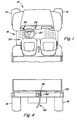
- FIG. 1 a vehicle 10 is shown with a frame 12 which is for movement over the Underground by two front, steerable wheels 14 and rear, drivable wheels 16 is supported.
- a Operator platform shown generally at 18, with a Operator seat zone 20 is provided on vehicle 10 and points usual controls such as a steering device 22, the is operatively connected to the wheels 14, and a Instrument panel with a switch or a Starter switch 24, which has a drive starting circuit or an ignition circuit 26, which is generally shown in FIGS. 2 and 3 is denoted by 26.
- the vehicle 10 as it is 1, includes a rear loading zone 28 behind the operator seat zone 20 and a rear one Frame section 32 (FIG. 4) below the loading zone 28.
- a jump start connection or connection device 36 (FIG. 4) is provided on the rear frame portion 32 and over a line 38 and an external starting circuit 40 (FIG. 2) with the Ignition circuit 26 connected.
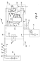
- the external starting circuit 40 has one Vehicle battery or a power source 42, which via a Line 43 is connected to a relay 44, which by the Foreign starter circuit 40 is controlled.
- the relay 44 is normally open and has a first switching terminal 51 on which is connected to line 38, and a second switching terminal 52, which corresponds to the positive output of the battery 42 connected is.
- the Foreign starter circuit 40 a normally open Operating switch or second switch 56, which in the Operator platform 18 on the instrument panel on the side of the Steering device 22 is provided to the starter switch or the switch 24 is opposite.
- the entrance of the second Switch 56 is through a diode 58 with the positive output the battery 42 and via a diode 60 to the line 38 connected.
- the output of the second switch 56 is one Control terminal 62 of the relay 44 connected. If the second Switch 56 is pressed and held by an operator the relay 44 will be activated to the circuit between the line 38 and the current source 42 and the ignition circuit 26 close when voltage to the input of the second switch 56 either from battery 42 or a separate one Voltage source via the connection device 36 and the line 38 is delivered.
- the ignition circuit 26 has a starting relay 70, which with a conventional starter 72 is connected to the vehicle 10.
- the starter relay 70 has a control connection 73, which is connected to the switch 24 on the instrument panel. Moving the switch 24 to the lowest starting position closes the circle between line 43 and the Control port 73 to close the starter relay 70 and the To supply starter 72 from line 43.
- an elongated one Foreign starter cable 70 a first connection or one Connection device 86, which is adapted to the Interacting device 36 of the vehicle 10.
- the opposite end of the external starter cable 80 has an im substantially identical connection device 86 'to which a connection to a connection device 36 'on a alternative power source or an auxiliary power source that shown generally at 90.
- Auxiliary power source 90 could be another vehicle that is in use is essentially identical to vehicle 10, with identical Operating voltage, connecting device 36 and external starting circuit 40 his. For example, if two are substantially identical Commercial vehicles with a system with a nominal voltage of 12 V with the system described above in the same area work and one of these vehicles has a discharged battery has, the vehicle in operation simply positioned next to the inoperative vehicle and that Foreign starter cable 80 with the connection devices 36 and 36 ' get connected. Both operators then press theirs corresponding second switch 56 to establish a connection between the good power source or the auxiliary power source 90 and the discharged battery or power source 42 to produce quickly charge the surface of the discharged battery cause.
- the operator of the inoperable Vehicle 10 may also use starter 72 of vehicle 10 operate by pressing switch 24 and the second switch 56 operated simultaneously while the other operator only operated the other second switch 56. Is this disabled vehicle charged or started by the External start system has been used, give the operators the second switches 56 free and disconnect the third-party starter cable 80 from the vehicles.
- the auxiliary power source 90 can also be another vehicle or a generator with an electrical system with a higher Output voltage than that of the vehicle 10.
- the Foreign starter cable 80 of the power source 90 is with the Connection device 36 connected to the line 38 with a relatively high voltage.
- the Operator presses the second switch 56 on the vehicle 10 to close relay 44 and to power source 90 with the discharged or inoperable power source 42 via the To connect line 43.
- the second switch 56 By keeping the second switch 56, the current source 42 through the High voltage power source or auxiliary power source 90 to be charged.
- the second switch 56 must keep printed for charging, the possibility of a Damage caused by overloading is essential reduced.
- the vehicle 10 must start by the auxiliary power source 90 high voltage the starter switch 24 and the second Press switch 56 at the same time. Because a positive action in Form of simultaneous operation of the spaced switches, of the switch 24 and the second switch 56 on the part of Operator by both hands is required less likely to cause damage by accidentally operating starter 72 too long by the high voltage auxiliary power source 90.
- the Foreign starter circuit 40 a normally closed relay or a second switch 44 ′, which is connected to the vehicle 10 arranged and connected to a third-party starter control 100, which is also provided on the vehicle 10.
- the External starter control 100 detects the voltage of the battery 42, the charging capacity of the power source 42, the time since Charging voltage has been applied, the frequency of closing of the second switch 44 ', and whether or not starting the Vehicle 10 was tried. Based on the recorded Foreign start controller 100 opens the second under conditions Switch 44 'to overcharge and damage the electrical Prevent system of the vehicle 10.
- the second switch 44 normally closed is a use of the Vehicle 10 for a jump start or around Deliver battery surge for another vehicle enables The operator simply includes Foreign starter cable 80 to the connecting device 36 and connects the foreign starter cable 80 to the electrical system of the inoperable vehicle or auxiliary power source 90.
- the external starting circuit 40 has a microcontroller 120, which is acted upon by a connection 122, which with a controlled voltage source, the one Zener diode 124 and one Has capacitor 126 is connected.
- a diode 128 for Protection from reverse polarity and one Voltage limiting resistor 130 connect terminal 122 with line 38.
- Zener diode 124 limits the voltage terminal 122 to approximately 5 V (Vcc).
- a voltage divider has resistors 132 and 134 and is a capacitor 136 with a sensor connection 138 of the microcontroller 120 and with Line 43 connected to a signal to the microcontroller 120 to deliver the voltage level across the battery 42 displays.
- a relay driver 140 is with an output 142 and with one Control input 144 of the relay 44 'connected.
- the relay driver 140 has an NPN transistor 150 with a grounded emitter and a base connected to the Sensor connection 142 and via a resistor 154 to ground are connected.
- the collector of transistor 150 is over Resistors 156 and 158 with line 38 through diode 128 connected.
- a PNP transistor 160 has a collector via a diode 162 with ground and with a control input 144 is connected. The emitter is connected to the diode 128 Line 38 connected.
- Selected connections of the microcontroller 120 can either be configured as an input or an output.
- the Sensor port 138 is first configured as an output and grounded to fully discharge capacitor 136. After that sensor port 138 is configured as an input what it allows capacitor 136 to start charging.
- the Charge rate is determined by the voltage on battery 42.
- Microcontroller 120 monitors the time it takes to charge capacitor 136 to a limit voltage, which is preferably half of Vcc or about 2.5V is. Based on the time to reach the Limit voltage, the microcontroller 120 calculates the to Resistor-capacitor circuit 132, 134 and 136 applied Tension. This sequence is then repeated, with the Microcontroller 120 the sensor port 138 as an output configured, which grounds the sensor terminal 138 and the Capacitor 136 discharges.
- This method one Voltage determination enables the use of a inexpensive microcontrollers without analog or digital Converter.
- the microcontroller 120 changes the output 142 from a low to a high or activated state which transistors 150 and 160 and switch 44 'activated to the circle between the alternative voltage source 90 and the Open battery 42. This way, a Surge protection provided.
- microcontroller 120 When the voltage on the battery or power source 42 drops, for example when the starter switch 26 is actuated microcontroller 120 lowers output 142 turn off transistors 150 and 160 and around relay 44 ' close to a battery charge and / or a To deliver starting voltage surge. The number of times that the switch 44 'has been clocked, and the timing of the Clock is monitored by microcontroller 120 to provide a Display of the state of charge of the power source 42, the duration, in the starter was activated and the number of Starter actuation cycles, with the alternative voltage source 90 to deliver. A separate connection of the microcontroller 120 can also be connected to the input of the starter switch 24 to monitor the actual starter charging time. If the charging time is too long or if a high number of Charge starting cycles are determined in a predetermined period of time, the microcontroller will open switch 44 '. A fast Relay clocking can indicate that the current source 42 is defective.
Landscapes
- Engineering & Computer Science (AREA)
- Chemical & Material Sciences (AREA)
- Combustion & Propulsion (AREA)
- Mechanical Engineering (AREA)
- General Engineering & Computer Science (AREA)
- Power Engineering (AREA)
- Charge And Discharge Circuits For Batteries Or The Like (AREA)
- Electric Propulsion And Braking For Vehicles (AREA)
Abstract
Description
- Fig. 1
- eine Ansicht eines Fahrzeugs von oben, an dem eine erfindungsgemäße Fremdanlaßeinrichtung eingesetzt werden kann,
- Fig. 2
- einen schematischen Schaltplan für eine erste Fremdanlaßeinrichtung,
- Fig. 3
- einen Schaltplan für eine zweite Fremdanlaßeinrichtung und
- Fig. 4
- eine rückwärtige Ansicht des Fahrzeugs aus Fig. 1 mit einem Fremdanlaßkabel.
| Bauteil: | Bezugszeichen | Wert |
| Widerstände | 130 und 156 | 1,2kΩ |
| 132 und 134 | 10kΩ | |
| 152 und 154 | 10kΩ | |
| 158 | 10kΩ | |
| Kondensatoren | 126 | 47 µF |
| 136 | 0,1 µF | |
| Mikrocontroller | 120 | PIC12C508 |
Claims (9)
- Gerät, insbesondere Fahrzeug (10), mit einem Anlasser (72), einer Stromquelle (42) und einem Schalter (24), über den der Anlasser (72) mit der Stromquelle (42) verbindbar ist, und einer Einrichtung zum Verbinden mit einer Zusatzstromquelle (90), gekennzeichnet durch einen zweiten Schalter (56), durch den die Verbindung zwischen der Einrichtung und der Stromquelle (42) und/oder dem Anlasser (72) unterbrochen werden kann.
- Gerät nach Anspruch 1, dadurch gekennzeichnet, daß die Einrichtung zumindest eine Anschlußeinrichtung (36) aufweist, die vorzugsweise mit einer zweiten, entsprechend ausgebildeten Anschlußeinrichtung (86, 86') selektiv zusammenwirken kann, die mit der Zusatzstromquelle (90) vorzugsweise über ein Kabel (80) verbindbar ist.
- Gerät nach einem oder mehreren der vorherigen Ansprüche, dadurch gekennzeichnet, daß die Zusatzstromquelle (90) von einem zweiten Fahrzeug bzw. einem an diesem angeordneten Bauteil, beispielsweise einer Fahrzeugbatterie, bereitgestellt wird.
- Gerät nach einem oder mehreren der vorherigen Ansprüche, dadurch gekennzeichnet, daß wenigstens einer der Schalter (24, 56) manuell betätigbar ist.
- Gerät nach Anspruch 5, dadurch gekennzeichnet, daß beide Schalter (24, 56) manuell betätigbar und vorzugsweise an einem Armaturenbrett des Fahrzeugs (10) derart beabstandet vorgesehen sind, daß zwischen ihnen ein weiteres Bedienungselement vorzugsweise in Form einer Lenkeinrichtung (22) vorsehbar ist.
- Gerät nach einem oder mehreren der vorherigen Ansprüche, dadurch gekennzeichnet, daß wenigstens einer der Schalter (24, 56) ein Relais (44, 44') aufweist bzw. als solches ausgebildet ist.
- Gerät nach einem oder mehreren der vorherigen Ansprüche, dadurch gekennzeichnet, daß zumindest der zweite Schalter (56) in Abhängigkeit von dem Spannungszustand der Stromquelle (42) öffnet bzw. schließt.
- Gerät nach einem oder mehreren der vorherigen Ansprüche, dadurch gekennzeichnet, daß der zweite Schalter (56) mittels eines Mikrocontrollers (120) angesteuert wird, der vorzugsweise den Spannungszustand der Stromquelle (42) vorzugsweise basierend auf der Dauer, die ein mit der Stromquelle (42) verbundener Kondensator (136) benötigt, um eine vorgegebene Grenzspannung zu erreichen, ermittelt.
- Gerät nach Anspruch 8, dadurch gekennzeichnet, daß der Mikrocontroller (120) den zweiten Schalter (56) in Abhängigkeit vom Schaltzustand des Anlassers (72) vorzugsweise derart ansteuert, daß er den Schalter (56) schließt, wenn der Anlasser (72) aktiviert wird.
Applications Claiming Priority (2)
| Application Number | Priority Date | Filing Date | Title |
|---|---|---|---|
| US346092 | 1999-07-01 | ||
| US09/346,092 US6281600B1 (en) | 1999-07-01 | 1999-07-01 | Jump start system for vehicles having different operating voltages |
Publications (3)
| Publication Number | Publication Date |
|---|---|
| EP1067648A2 true EP1067648A2 (de) | 2001-01-10 |
| EP1067648A3 EP1067648A3 (de) | 2004-01-14 |
| EP1067648B1 EP1067648B1 (de) | 2006-01-04 |
Family
ID=23357910
Family Applications (1)
| Application Number | Title | Priority Date | Filing Date |
|---|---|---|---|
| EP00113647A Expired - Lifetime EP1067648B1 (de) | 1999-07-01 | 2000-06-28 | Gerät, insbesondere Fahrzeug |
Country Status (5)
| Country | Link |
|---|---|
| US (1) | US6281600B1 (de) |
| EP (1) | EP1067648B1 (de) |
| AU (1) | AU763240B2 (de) |
| CA (1) | CA2298198A1 (de) |
| DE (1) | DE50012004D1 (de) |
Cited By (3)
| Publication number | Priority date | Publication date | Assignee | Title |
|---|---|---|---|---|
| EP1201485A1 (de) * | 2000-09-08 | 2002-05-02 | Ford Motor Company | Lader/Generatoreinheit für ein elektrisches Hybridfahrzeug |
| WO2011144490A1 (en) * | 2010-05-17 | 2011-11-24 | Tyco Electronics Amp Gmbh | Method and circuit for inverse polarity protection circuit for a jump-start terminal |
| WO2012104193A1 (de) * | 2011-02-03 | 2012-08-09 | Bayerische Motoren Werke Aktiengesellschaft | Kraftfahrzeug mit einer fremdstartvorrichtung |
Families Citing this family (21)
| Publication number | Priority date | Publication date | Assignee | Title |
|---|---|---|---|---|
| DE10011404C2 (de) * | 2000-03-09 | 2003-05-15 | Daimler Chrysler Ag | Einrichtung und Verfahren zur Erkennung einer Fremdenergieversorgung insbesondere eines Kraftfahrzeuges |
| US7345450B2 (en) * | 2002-02-19 | 2008-03-18 | V Ector Products, Inc. | Microprocessor controlled booster apparatus with polarity protection |
| WO2003104070A2 (en) * | 2002-06-07 | 2003-12-18 | Brumby Corporation Limited | Motorcycle |
| US6803743B2 (en) * | 2002-10-04 | 2004-10-12 | Delphi Technologies, Inc. | Jump start and reverse battery protection circuit |
| CA2500602A1 (en) * | 2005-03-07 | 2006-09-07 | Ali R. Abolfathi | Starter motor for motor vehicle engine |
| US20070032127A1 (en) * | 2005-08-04 | 2007-02-08 | Spx Corporation | Method and apparatus for saving volatile memory settings in a vehicle |
| DE102007056779A1 (de) * | 2007-11-23 | 2009-06-04 | Rainer Diederich | Fahrzeug |
| US9263907B2 (en) | 2008-01-03 | 2016-02-16 | F.D. Richardson Enterprises, Inc. | Method and apparatus for providing supplemental power to an engine |
| US20090174362A1 (en) * | 2008-01-03 | 2009-07-09 | F.D. Richardson Enterprises, Inc. Doing Business As Richardson Jumpstarters | Method and apparatus for providing supplemental power to an engine |
| US8493021B2 (en) * | 2008-01-03 | 2013-07-23 | F. D. Richardson Entereprises, Inc. | Method and apparatus for providing supplemental power to an engine |
| US20140375066A1 (en) * | 2013-06-19 | 2014-12-25 | Tai-Her Yang | Combustion and emergency start controlling device having auxiliary power source and system thereof |
| WO2015149134A1 (en) * | 2014-04-02 | 2015-10-08 | Bookleaf Pty Ltd | Battery management system and method and battery powered appliance incorporating the same |
| US9866047B2 (en) | 2014-04-15 | 2018-01-09 | Connect-Ease L.L.C. | Multi-battery and multi-device connection system |
| US9559473B2 (en) | 2014-04-15 | 2017-01-31 | Connect-Ease L. L. C. | Multi-battery and multi-device connection system |
| US20160053737A1 (en) * | 2014-08-21 | 2016-02-25 | Kold Ban International, Ltd. | Plc controlled supplemental starting system |
| US10052965B2 (en) * | 2014-09-30 | 2018-08-21 | Ford Global Technologies, Llc | Method for charging the starter battery of a vehicle |
| KR101795169B1 (ko) * | 2015-11-25 | 2017-11-07 | 현대자동차주식회사 | 배터리 점프 시동 방법 |
| US20170203666A1 (en) * | 2016-01-19 | 2017-07-20 | Ford Global Technologies, Llc | Battery charging system and servicing method |
| KR101786347B1 (ko) * | 2016-05-20 | 2017-10-18 | 현대자동차주식회사 | 점프 스타트를 위한 차량의 전력 시스템 |
| AU2018336995B2 (en) * | 2017-09-22 | 2021-09-09 | The Noco Company | Rechargeable battery jump starting device with control switch backlight system |
| US11527897B1 (en) * | 2021-05-21 | 2022-12-13 | Deltran Operations Usa, Inc. | Battery charger and engine jump start system with automatic operating mode via a single output receptacle |
Family Cites Families (11)
| Publication number | Priority date | Publication date | Assignee | Title |
|---|---|---|---|---|
| US3942027A (en) * | 1974-05-24 | 1976-03-02 | Raoul Fima | Internally mounted battery jump cables |
| GB1554161A (en) * | 1976-10-21 | 1979-10-17 | Lucas Industries Ltd | Cycles |
| US4233552A (en) | 1978-06-28 | 1980-11-11 | Associated Equipment Corporation | Vehicle-starting circuit with excessive voltage detection |
| US4286172A (en) | 1979-10-09 | 1981-08-25 | Millonzi Anthony B | Safety jumper cables |
| US4701688A (en) | 1984-05-10 | 1987-10-20 | Guim R | Safety booster cables with time delay |
| US4769586A (en) * | 1986-03-07 | 1988-09-06 | Kazmierowicz Thaddeus V | Battery jumper cable apparatus |
| US4999562A (en) | 1988-10-05 | 1991-03-12 | Hill William L | Jumper terminal system |
| US5162720A (en) * | 1991-10-15 | 1992-11-10 | Lambert Gordon K | Vehicle electrical system |
| AU688269B2 (en) * | 1992-08-18 | 1998-03-12 | Glorywin International Group Limited | 3-pole battery switches |
| JP3539988B2 (ja) * | 1993-06-25 | 2004-07-07 | 株式会社デンソー | 車両用スタータ装置 |
| FR2715696A1 (fr) * | 1994-01-28 | 1995-08-04 | Capet Bernard | Utilisation de l'énergie électrique distribuée par les réseaux pour assurer le démarrage des véhicules à moteur thermique. |
-
1999
- 1999-07-01 US US09/346,092 patent/US6281600B1/en not_active Expired - Lifetime
-
2000
- 2000-02-08 CA CA 2298198 patent/CA2298198A1/en not_active Abandoned
- 2000-06-22 AU AU42628/00A patent/AU763240B2/en not_active Ceased
- 2000-06-28 EP EP00113647A patent/EP1067648B1/de not_active Expired - Lifetime
- 2000-06-28 DE DE50012004T patent/DE50012004D1/de not_active Expired - Lifetime
Cited By (4)
| Publication number | Priority date | Publication date | Assignee | Title |
|---|---|---|---|---|
| EP1201485A1 (de) * | 2000-09-08 | 2002-05-02 | Ford Motor Company | Lader/Generatoreinheit für ein elektrisches Hybridfahrzeug |
| WO2011144490A1 (en) * | 2010-05-17 | 2011-11-24 | Tyco Electronics Amp Gmbh | Method and circuit for inverse polarity protection circuit for a jump-start terminal |
| WO2012104193A1 (de) * | 2011-02-03 | 2012-08-09 | Bayerische Motoren Werke Aktiengesellschaft | Kraftfahrzeug mit einer fremdstartvorrichtung |
| US9718419B2 (en) | 2011-02-03 | 2017-08-01 | Bayerische Motoren Werke Aktiengesellschaft | Motor vehicle having a jump-start device between at least two on-board electric power systems |
Also Published As
| Publication number | Publication date |
|---|---|
| DE50012004D1 (de) | 2006-03-30 |
| US6281600B1 (en) | 2001-08-28 |
| AU4262800A (en) | 2001-01-04 |
| AU763240B2 (en) | 2003-07-17 |
| EP1067648A3 (de) | 2004-01-14 |
| CA2298198A1 (en) | 2001-01-01 |
| EP1067648B1 (de) | 2006-01-04 |
Similar Documents
| Publication | Publication Date | Title |
|---|---|---|
| EP1067648B1 (de) | Gerät, insbesondere Fahrzeug | |
| EP0568655B1 (de) | Vorrichtung zur spannungsversorgung in einem kraftfahrzeug | |
| EP1232073B1 (de) | Zwei-batteriensystem | |
| EP0766780B1 (de) | Verfahren zum steuern der elektrischen beheizung eines katalysators | |
| DE102013200763A1 (de) | System und verfahren für das fahrzeugenergiemanagement | |
| DE2829618A1 (de) | Zweispannungsbatteriesystem und elektronischer schalter fuer dasselbe | |
| DE69813862T2 (de) | Verfahren und einrichtung zur ladesteuerung in einem elektrischen system mit zwei batterien | |
| DE102008044405A1 (de) | Elektronische Airbag Steuereinheit mit autarkem Ereignisdatenrecorder | |
| DE102007003424A1 (de) | Vorrichtung, System und Verfahren zur Verringerung eines Ruhestromverbrauches eines Kraftfahrzeuges | |
| DE1933656C3 (de) | Spannungsregler für eine gleichstromerregte Drehstromlichtmaschine eines Kraftfahrzeugs | |
| DE102011121580A1 (de) | Energieversorgung eines Nutzfahrzeuganhängers | |
| DE102005026646A1 (de) | Vorrichtung und Verfahren zum automatischen Aufladen einer Hochspannungsbatterie in einem Hybrid-Elektrofahrzeug | |
| EP2946965A1 (de) | Vorrichtung und verfahren zur begrenzung des einschaltstroms beim betreiben einer kapazitiven last an einem dreiphasenwechselrichter | |
| DE102014105040B4 (de) | Vorrichtung und Verfahren zum Stabilisieren einer Fahrzeugspannung | |
| DE69023809T2 (de) | Elektrisches Energieverteilungssystem. | |
| DE2831588A1 (de) | Zentrale speisevorrichtung, insbesondere fuer gewerbliche und reisefahrzeuge, z.b. fuer lieferfahrzeuge, motorcaravans, campingwagen und boote | |
| EP0885786A2 (de) | Ablaufschaltung für Sitzgurte | |
| DE1809805C3 (de) | Batterie-Ladegerät | |
| DE102021128806A1 (de) | Bordnetz für ein Kraftfahrzeug und Verfahren zur Energiebereitstellung in einem Bordnetz | |
| DE3006109A1 (de) | Batterieladesystem | |
| EP1825529B1 (de) | Elektrische schaltung zur ansteuerung eines piezoelektrischen elements insbesondere einer kraftstoffeinspritzanlage eines kraftfahrzeugs | |
| DE3622157A1 (de) | Verfahren und schaltungsanordnung zur speisung von haupt- und nebenverbrauchern in einem fahrzeug | |
| EP1825123A1 (de) | Elektrische schaltung zur ansteuerung eines piezoelektrischen elements insbesondere einer kraftstoffeinspritzanlage eines kraftfahrzeugs | |
| DE102010020746B4 (de) | Verpolschutzschaltung und Verfahren zum Bereitstellen eines Verpolschutzes | |
| DE112022005303T5 (de) | Steuereinrichtung |
Legal Events
| Date | Code | Title | Description |
|---|---|---|---|
| PUAI | Public reference made under article 153(3) epc to a published international application that has entered the european phase |
Free format text: ORIGINAL CODE: 0009012 |
|
| AK | Designated contracting states |
Kind code of ref document: A2 Designated state(s): AT BE CH CY DE DK ES FI FR GB GR IE IT LI LU MC NL PT SE |
|
| AX | Request for extension of the european patent |
Free format text: AL;LT;LV;MK;RO;SI |
|
| PUAL | Search report despatched |
Free format text: ORIGINAL CODE: 0009013 |
|
| AK | Designated contracting states |
Kind code of ref document: A3 Designated state(s): AT BE CH CY DE DK ES FI FR GB GR IE IT LI LU MC NL PT SE |
|
| AX | Request for extension of the european patent |
Extension state: AL LT LV MK RO SI |
|
| 17P | Request for examination filed |
Effective date: 20040714 |
|
| AKX | Designation fees paid |
Designated state(s): DE FR GB IT NL |
|
| 17Q | First examination report despatched |
Effective date: 20050131 |
|
| GRAP | Despatch of communication of intention to grant a patent |
Free format text: ORIGINAL CODE: EPIDOSNIGR1 |
|
| GRAS | Grant fee paid |
Free format text: ORIGINAL CODE: EPIDOSNIGR3 |
|
| GRAA | (expected) grant |
Free format text: ORIGINAL CODE: 0009210 |
|
| AK | Designated contracting states |
Kind code of ref document: B1 Designated state(s): DE FR GB IT NL |
|
| PG25 | Lapsed in a contracting state [announced via postgrant information from national office to epo] |
Ref country code: NL Free format text: LAPSE BECAUSE OF FAILURE TO SUBMIT A TRANSLATION OF THE DESCRIPTION OR TO PAY THE FEE WITHIN THE PRESCRIBED TIME-LIMIT Effective date: 20060104 |
|
| REG | Reference to a national code |
Ref country code: GB Ref legal event code: FG4D Free format text: NOT ENGLISH |
|
| GBT | Gb: translation of ep patent filed (gb section 77(6)(a)/1977) |
Effective date: 20060208 |
|
| REF | Corresponds to: |
Ref document number: 50012004 Country of ref document: DE Date of ref document: 20060330 Kind code of ref document: P |
|
| PGFP | Annual fee paid to national office [announced via postgrant information from national office to epo] |
Ref country code: FR Payment date: 20060620 Year of fee payment: 7 |
|
| PGFP | Annual fee paid to national office [announced via postgrant information from national office to epo] |
Ref country code: IT Payment date: 20060630 Year of fee payment: 7 |
|
| NLV1 | Nl: lapsed or annulled due to failure to fulfill the requirements of art. 29p and 29m of the patents act | ||
| ET | Fr: translation filed | ||
| PLBE | No opposition filed within time limit |
Free format text: ORIGINAL CODE: 0009261 |
|
| STAA | Information on the status of an ep patent application or granted ep patent |
Free format text: STATUS: NO OPPOSITION FILED WITHIN TIME LIMIT |
|
| 26N | No opposition filed |
Effective date: 20061005 |
|
| REG | Reference to a national code |
Ref country code: FR Ref legal event code: ST Effective date: 20080229 |
|
| PG25 | Lapsed in a contracting state [announced via postgrant information from national office to epo] |
Ref country code: FR Free format text: LAPSE BECAUSE OF NON-PAYMENT OF DUE FEES Effective date: 20070702 |
|
| PG25 | Lapsed in a contracting state [announced via postgrant information from national office to epo] |
Ref country code: IT Free format text: LAPSE BECAUSE OF NON-PAYMENT OF DUE FEES Effective date: 20070628 |
|
| PGFP | Annual fee paid to national office [announced via postgrant information from national office to epo] |
Ref country code: DE Payment date: 20140521 Year of fee payment: 15 |
|
| REG | Reference to a national code |
Ref country code: DE Ref legal event code: R119 Ref document number: 50012004 Country of ref document: DE |
|
| PG25 | Lapsed in a contracting state [announced via postgrant information from national office to epo] |
Ref country code: DE Free format text: LAPSE BECAUSE OF NON-PAYMENT OF DUE FEES Effective date: 20160101 |
|
| PGFP | Annual fee paid to national office [announced via postgrant information from national office to epo] |
Ref country code: GB Payment date: 20190627 Year of fee payment: 20 |
|
| REG | Reference to a national code |
Ref country code: GB Ref legal event code: PE20 Expiry date: 20200627 |
|
| PG25 | Lapsed in a contracting state [announced via postgrant information from national office to epo] |
Ref country code: GB Free format text: LAPSE BECAUSE OF EXPIRATION OF PROTECTION Effective date: 20200627 |