EP1067570A2 - An assembling apparatus and an assembling method - Google Patents
An assembling apparatus and an assembling method Download PDFInfo
- Publication number
- EP1067570A2 EP1067570A2 EP00114093A EP00114093A EP1067570A2 EP 1067570 A2 EP1067570 A2 EP 1067570A2 EP 00114093 A EP00114093 A EP 00114093A EP 00114093 A EP00114093 A EP 00114093A EP 1067570 A2 EP1067570 A2 EP 1067570A2
- Authority
- EP
- European Patent Office
- Prior art keywords
- parts
- holding
- fuses
- fuse
- pair
- Prior art date
- Legal status (The legal status is an assumption and is not a legal conclusion. Google has not performed a legal analysis and makes no representation as to the accuracy of the status listed.)
- Withdrawn
Links
Images


Classifications
-
- H—ELECTRICITY
- H01—ELECTRIC ELEMENTS
- H01H—ELECTRIC SWITCHES; RELAYS; SELECTORS; EMERGENCY PROTECTIVE DEVICES
- H01H85/00—Protective devices in which the current flows through a part of fusible material and this current is interrupted by displacement of the fusible material when this current becomes excessive
- H01H85/02—Details
- H01H85/0208—Tools for inserting and removing fuses
-
- Y—GENERAL TAGGING OF NEW TECHNOLOGICAL DEVELOPMENTS; GENERAL TAGGING OF CROSS-SECTIONAL TECHNOLOGIES SPANNING OVER SEVERAL SECTIONS OF THE IPC; TECHNICAL SUBJECTS COVERED BY FORMER USPC CROSS-REFERENCE ART COLLECTIONS [XRACs] AND DIGESTS
- Y10—TECHNICAL SUBJECTS COVERED BY FORMER USPC
- Y10T—TECHNICAL SUBJECTS COVERED BY FORMER US CLASSIFICATION
- Y10T29/00—Metal working
- Y10T29/49—Method of mechanical manufacture
- Y10T29/49002—Electrical device making
- Y10T29/49117—Conductor or circuit manufacturing
- Y10T29/49124—On flat or curved insulated base, e.g., printed circuit, etc.
- Y10T29/4913—Assembling to base an electrical component, e.g., capacitor, etc.
-
- Y—GENERAL TAGGING OF NEW TECHNOLOGICAL DEVELOPMENTS; GENERAL TAGGING OF CROSS-SECTIONAL TECHNOLOGIES SPANNING OVER SEVERAL SECTIONS OF THE IPC; TECHNICAL SUBJECTS COVERED BY FORMER USPC CROSS-REFERENCE ART COLLECTIONS [XRACs] AND DIGESTS
- Y10—TECHNICAL SUBJECTS COVERED BY FORMER USPC
- Y10T—TECHNICAL SUBJECTS COVERED BY FORMER US CLASSIFICATION
- Y10T29/00—Metal working
- Y10T29/53—Means to assemble or disassemble
- Y10T29/5313—Means to assemble electrical device
- Y10T29/53174—Means to fasten electrical component to wiring board, base, or substrate
- Y10T29/53178—Chip component
-
- Y—GENERAL TAGGING OF NEW TECHNOLOGICAL DEVELOPMENTS; GENERAL TAGGING OF CROSS-SECTIONAL TECHNOLOGIES SPANNING OVER SEVERAL SECTIONS OF THE IPC; TECHNICAL SUBJECTS COVERED BY FORMER USPC CROSS-REFERENCE ART COLLECTIONS [XRACs] AND DIGESTS
- Y10—TECHNICAL SUBJECTS COVERED BY FORMER USPC
- Y10T—TECHNICAL SUBJECTS COVERED BY FORMER US CLASSIFICATION
- Y10T29/00—Metal working
- Y10T29/53—Means to assemble or disassemble
- Y10T29/5313—Means to assemble electrical device
- Y10T29/53187—Multiple station assembly apparatus
-
- Y—GENERAL TAGGING OF NEW TECHNOLOGICAL DEVELOPMENTS; GENERAL TAGGING OF CROSS-SECTIONAL TECHNOLOGIES SPANNING OVER SEVERAL SECTIONS OF THE IPC; TECHNICAL SUBJECTS COVERED BY FORMER USPC CROSS-REFERENCE ART COLLECTIONS [XRACs] AND DIGESTS
- Y10—TECHNICAL SUBJECTS COVERED BY FORMER USPC
- Y10T—TECHNICAL SUBJECTS COVERED BY FORMER US CLASSIFICATION
- Y10T29/00—Metal working
- Y10T29/53—Means to assemble or disassemble
- Y10T29/53313—Means to interrelatedly feed plural work parts from plural sources without manual intervention
- Y10T29/53365—Multiple station assembly apparatus
-
- Y—GENERAL TAGGING OF NEW TECHNOLOGICAL DEVELOPMENTS; GENERAL TAGGING OF CROSS-SECTIONAL TECHNOLOGIES SPANNING OVER SEVERAL SECTIONS OF THE IPC; TECHNICAL SUBJECTS COVERED BY FORMER USPC CROSS-REFERENCE ART COLLECTIONS [XRACs] AND DIGESTS
- Y10—TECHNICAL SUBJECTS COVERED BY FORMER USPC
- Y10T—TECHNICAL SUBJECTS COVERED BY FORMER US CLASSIFICATION
- Y10T29/00—Metal working
- Y10T29/53—Means to assemble or disassemble
- Y10T29/53313—Means to interrelatedly feed plural work parts from plural sources without manual intervention
- Y10T29/5337—Means to interrelatedly feed plural work parts from plural sources without manual intervention including assembly pallet
-
- Y—GENERAL TAGGING OF NEW TECHNOLOGICAL DEVELOPMENTS; GENERAL TAGGING OF CROSS-SECTIONAL TECHNOLOGIES SPANNING OVER SEVERAL SECTIONS OF THE IPC; TECHNICAL SUBJECTS COVERED BY FORMER USPC CROSS-REFERENCE ART COLLECTIONS [XRACs] AND DIGESTS
- Y10—TECHNICAL SUBJECTS COVERED BY FORMER USPC
- Y10T—TECHNICAL SUBJECTS COVERED BY FORMER US CLASSIFICATION
- Y10T29/00—Metal working
- Y10T29/53—Means to assemble or disassemble
- Y10T29/534—Multiple station assembly or disassembly apparatus
-
- Y—GENERAL TAGGING OF NEW TECHNOLOGICAL DEVELOPMENTS; GENERAL TAGGING OF CROSS-SECTIONAL TECHNOLOGIES SPANNING OVER SEVERAL SECTIONS OF THE IPC; TECHNICAL SUBJECTS COVERED BY FORMER USPC CROSS-REFERENCE ART COLLECTIONS [XRACs] AND DIGESTS
- Y10—TECHNICAL SUBJECTS COVERED BY FORMER USPC
- Y10T—TECHNICAL SUBJECTS COVERED BY FORMER US CLASSIFICATION
- Y10T29/00—Metal working
- Y10T29/53—Means to assemble or disassemble
- Y10T29/53435—Means to assemble or disassemble including assembly pallet
Definitions
- the present invention relates to an assembling apparatus, in particular to a fuse box assembling apparatus, for mounting a plurality of electric and/or electronic parts, in particular fuses in a receiving member such as a box and/or a board, in particular to assemble a fuse box used, for example, in an automotive vehicle. Furthermore, the present invention relates to an assembling method, in particular to a fuse box assembling method.
- the aforementioned fuse box is such that a plurality of fuses as parts are mounted in a box as a base.
- the fuses to be inserted come in a plurality of kinds having different sizes and configurations.
- This assembling apparatus is provided with a plurality of parts feeder provided for the respective kinds of fuses for successively feeding fuses, and an inserting unit for taking out the fuses one by one from the respective parts feeder and inserting them into a box.
- the inserting unit includes a clamping device for clamping the fuse and an arm mechanism for moving the clamping device between the respective parts feeders and the box.
- the respective parts feeders are arrayed side by side at one end thereof, whereas the box is provided at the other end thereof.
- One fuse is selected from each parts feeder, taken out by the inserting unit, conveyed from the one end of the assembling apparatus to the other end thereof, and inserted into the box. After a series of these operations are repeated for all fuses, assembling of the fuse box is completed.
- the fuse is taken out from the respective parts feeders every time the fuse is to be inserted. It takes time and the fuse inserting operation cannot be performed while the clamping device moves between the parts feeders and the box. As a result, a tact time for assembling one fuse box tends to be longer.
- the above fuse box is assembled by inserting a plurality of fuses into a box, and these fuses come in a plurality of kinds having different sizes and configurations.
- a fuse box assembling apparatus is provided with parts feeders provided for the respective kinds of fuses for successively feeding the fuses along transport rails, and inserting units for receiving the fuses one by one from the parts feeders and inserting them into a box.
- Each inserting unit includes clamping hands for clamping the fuse and an arm mechanism for moving the clamping hands between the corresponding parts feeder and the box.
- the configurations of the fuses differ, the configurations of the transport rails of the parts feeder and the configurations and opening amount of the clamping hands may need to be differed.
- an insertion station constructed by the parts feeder and the inserting unit is provided for each kind of the fuses and specially used therefor.
- the assembling apparatus tends to become larger if the parts feeder and the inserting unit are specially provided for each kind of the fuses.
- the present invention was developed to solve the above technical problem, and an object thereof is to provide an assembling apparatus and an assembling method which allow to easily mount a plurality of electric and/or electronic parts, in particular which can quickly mount a plurality of different kinds of fuses despite its simple construction.
- an assembling apparatus for mounting a plurality of electric/electronic parts, preferably fuses in or on or at a receiving member, preferably in or on a box and/or on a board, in particular an electric or electronic board, comprising:
- the apparatus further comprises a plurality of fixed parts feeding units, each including a parts chamber for at least partly accommodating a specified kind of parts, preferably of fuses, and a feeding mechanism for successively feeding the accommodated parts.
- the second parts holding member is movable between positions substantially facing the respective parts feeding units and a position substantially facing the mounting unit, holds a plurality of parts in the order that they are mounted by being moved successively to the positions substantially facing the parts feeding units accommodating the parts necessary to assemble the receiving member, receiving and holding the parts fed from the parts feeding units, and is then moved to the position substantially facing the mounting unit.
- a fuse box (or board) assembling apparatus for mounting a plurality of fuses in a box, comprising:
- a fuse collecting operation for a fuse box to be assembled next is performed simultaneously with a fuse mounting operation for the fuse box being assembled.
- the collected fuses can be transferred at once to the mounting unit by the transferring mechanism. As a result, the pause of the mounting unit for the preparation of parts can be suppressed, thereby shortening a tact time.
- the construction of the fuse box assembling apparatus can be simplified since it is not necessary to provide many mounting units, transferring mechanisms and parts holding members.
- the parts holding member is moved to the positions corresponding to or substantially facing the plurality of parts feeding units in a specified sequence to receive and hold a plurality of parts or fuses in the order that they are to be mounted while the mounting unit is at least partly mounting the parts or fuses in the receiving member, preferably in the box.
- an assembling method for mounting a plurality of electric/electronic parts preferably fuses in or on or at a receiving member, preferably in or on a box and/or in or on a (electri/electronic) board, comprising:
- the step of moving the second parts holding member to the position(s) where the plurality of parts feeding units is at least partially performed at the same time with the step of at least partly mounting the parts in the receiving member by means of the mounting unit.
- an assembling apparatus for mounting a plurality of kinds of electric/electronic parts, preferably of fuses, having different configurations in or on or at a receiving member, preferably in or on a box and/or in or on a (electric/electronic) board, comprising:
- the at least one pair of locking portions have a steplike shape comprised of a recessed upper portion and a projecting lower portion in such a manner as to correspond to the plurality of parts, and on which projected portions formed at upper portions of side surfaces of the parts are placeable when the pair of holding members are closed with respect to each other.
- a fuse box assembling apparatus for mounting a plurality of kinds of fuses having different configurations in a box, comprising:
- the fuse fed through the outlet by the transferring mechanism is received between the pair of holding members and held by being placed on the pair of locking portions corresponding thereto.
- the fuse can be mounted in the box when the pair of holding members are displaced downward by the vertically displacing mechanism.
- the pair of holding members are constructed such that the projected portion of the fuse is placed on the pair of locking portions with the holding members closed, it is sufficient to form the locking portions which are spaced apart by a specified distance.
- a construction for holding the fuse can be simplified.
- both the parts holding member and the pair of holding members can handle a plurality of kinds of fuses, it is sufficient to provide one each of the parts holding member, the pair of holding members, and other associated mechanisms including the vertically displacing mechanism. Therefore, the inventive assembling apparatus can be made smaller than the conventional assembling apparatuses which require a plurality of each of the above members and mechanisms.
- the pair of holding members comprise:
- the respective pairs of locking portions can be easily arranged using the pair of locking portions of the second facing members for large-size fuses while using those of the first facing members for small-size fuses.
- the first and second facing members can be displaced downward as a unit and the corresponding fuses can be inserted into the box using the respective pairs of locking portions.
- the second facing members are subjected to an upward acting reaction force, and the first and second facing members are vertically displaced with respect to each other while the slanted surfaces are sliding along each other. Accordingly, the second facing members can be automatically opened to release the fuse.
- first and second facing members are vertically displaced with respect to each other when the fuse locked by the locking portions of the first facing members is inserted into the box, only the first facing members can be displaced downward while opening the second facing members. As a result, the second facing members are unlikely to stand as a hindrance.
- the pair of locking portions have slanted surfaces, which are slanted downward in facing directions, on its portion where the part or fuse is placed.
- an assembling method for mounting a plurality of kinds of electric/electronic parts, preferably of fuses, having different configurations in or on or at a receiving member, preferably in or on a box and/or in or on a (electric/electronic) board, comprising:
- the holding members are opened to discharge the part in the receiving member and wherein the holding members are vertically displaced while being substantially closed, so as to at least partly mount the part in the receiving member.
- the part is at least partly mounted by means of first holding members being substantially closed while being discharged by the opening of second holding members, the first holding member pushing the part from above upon being vertically displaced.
- the electrical/electronic part and/or fuse box assembling apparatus (hereinafter, assembling apparatus") 1 is for mounting a plurality of fuses in a box.
- the fuses come in a plurality of kinds having different sizes and configurations. In the following reference is made only to fuses. However, it should be understood that any other electric and/or electronic part or device such as capacitors, relays, resistors, transistors, wires, wiring boards, busbars, chips, etc. may be mounted in the box according to a preferred embodiment of the invention.
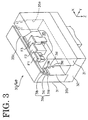
- the assembling apparatus 1 is provided with a plurality of parts feeding units 2 for feeding fuses at a specified timing, a movable magazine 30 as a parts holding member which is movably or displaceably provided so as to receive the fuses from the parts feeding units 2 and holds a plurality of fuses, a mounting unit 4 for preferably transferring the fuses from the movable magazine 30 to a fixed magazine 40 and successively mounting the transferred fuses in a box by means of an inserting mechanism 7, a moving or displacing unit 5 for moving or displacing the movable magazine 30 to the mounting unit 4 so that the fuses from the respective parts feeding units 2 can be transferred to the mounting unit 4, a controller 10 (see FIG.
- a discharge cylinder 12 for discharging the fuses from the movable magazine 30 and a container 13 for containing the fuses discharged from the discharge cylinder 12 are also provided on the frame 11.
- the fuses are fed from the respective parts feeding units 2 for each of the respective kinds.
- each parts feeding unit 2 a plurality of fuses are fed along a transport rail 21a from a parts feeder 21 while being aligned, and are pushed out one by one through outlets 2a by cylinders 23.
- the respective parts feeding units 2 are arranged at an angle different from 0° or 180°, preferably substantially transversely arranged with respect to a main direction of a moving mechanism 8 to be described later, the respective parts feeding units 2 being arranged substantially side by side at a lateral or rear part of the frame 11 and each have outlets 2a in two positions. These outlets 2a are open forward, and transversely juxtaposed substantially at the same height.
- a space for displacing the movable magazine 30 is provided right in front of the respective outlets 2a.
- the movable magazine 30 is transversely moved by the displacing unit 5 to be located in a specified position.
- the displacing unit 5 includes, for example, a toothed pulley driven by a stepped motor, a toothed belt 52 meshable with the toothed pulley 51, a connecting member 54 drivingly coupled to the toothed belt 52, and a direct-acting bearing 53 for guiding the connecting member 54, thereby constructing a direct-acting positioning mechanism.
- the movable magazine 30 is displaced to stop right in front of or in a position corresponding to the outlet 2a of an other parts feeding unit 2. Then, an other fuse enters the movable magazine 30 through the outlet 2a of this other parts feeding unit 2, thereby pushing the one fuse already located in the movable medicines 30 forward. If the above operations are repeated in a predetermined sequence for the respective fuses, a plurality of fuses necessary to assemble one fuse box are held in the movable magazine 30 while being substantially aligned in a line substantially along the forward/backward direction in a specified order.
- the movable magazine 30 When the necessary fuses are collected in the movable magazine 30, the movable magazine 30 is displaced such that the outlet at the front end of the movable magazine 30 faces or substantially corresponds to an inlet at the rear end of the fixed magazine 40 of the mounting unit 4.
- the fuses are transferred forward (a direction opposite from the direction X) at once from the movable magazine 30 to the fixed magazine 40 by a transferring mechanism 6 of the mounting unit 4 while maintaining their order of alignment.
- the fuses are successively fed one by one through the outlet at the front end of the fixed magazine 40 by the transferring mechanism 6, and are inserted into the box by the inserting mechanism 7. Simultaneously, the box is positioned in a specified position along horizontal direction by a moving unit 8. In this way, the respective fuses are or can be inserted in the specified positions of the box, and the box is pulled to a detachment position at front by the moving unit 8 when the insertion of the necessary fuses is completed, and is replaced by a box to be assembled next.
- the fuses necessary to assemble a next box are collected in the movable magazine 30 while the fuses are inserted into the box being assembled by the mounting unit 4.
- a tact time required for assembling can be shortened.
- this embodiment is designed to make the assembling apparatus smaller and to enable the insertion of a plurality of fuses having different configurations into a box by the fixed magazine 40 of the mounting unit 4 and a pair of holding members 70 of the inserting unit 7.
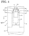
- each parts feeding unit 2 includes a so-called parts feeder 21 for feeding the fuses and/or the electric/electronic parts substantially along a transport rail 21a while successively aligning them in a predetermined orientation, an accommodating member 22 provided at the rear end of the transport rail 21a for receiving and accommodating the fuses to be moved to either one of the outlets 2a, and two cylinders 23 as a mechanism for feeding the fuses out through the respective outlets 2a.
- fuse accommodating chambers 22a, 22b each for at least partly accommodating one fuse are arranged substantially side-by-side.
- the accommodating member 22 can be transversely moved by a cylinder 24, so that the fuse accommodated in the right fuse accommodating chamber 22a can be moved to the right outlet 2a while the fuse accommodated in the left fuse accommodating chamber 22b can be moved to the left outlet 2a.
- a testing device (not shown) for testing the fuse held at the rear end of the transport rail 21 a is also provided. The testing device tests whether or not the fuse is electrically conductive or whether the corresponding electric/electronic part is correctly functioning by vertically moving a probe 26 by a cylinder 27 thereby contacting the fuse and/or the electric/electronic part.
- the fuse is received by coming into contact with a contact surface 21b upon reaching the rear end of the transport rail 21a, and tested by the testing device.
- One tested fuse is so arranged as to substantially face one of the outlets 2a by the accommodating member 22. If the above test result is satisfactory, the fuse facing the outlet 2a is pushed by the cylinder 23 provided behind in synchronism with the facing timing of the movable magazine 30 with respect to the outlet 2a, thereby being caused to enter the movable magazine 30 substantially facing the outlet 2a.
- the movable magazine 30 and/or the fixed magazine 40 include(s) a pair of facing members 31, and a connecting member 32 connecting the bottom ends of the facing members 31.
- the pair of facing members 31 are arranged substantially side by side, and a holding chamber 35 for holding the fuses is defined therebetween.
- the holding chamber 35 has such a size as to accommodate a specified (predetermined or predeterminable) number of fuses, and holds fuses having different configurations in alignment along the forward/backward direction. These fuses are necessary to assemble a fuse box and are aligned in an order that they are mounted in the box.
- a guide surface 31a is formed at a portion of each facing member 31 which serves as an inner surface of the holding chamber 35.
- An inlet 35a is open at the rear end of the holding chamber 35, and the fuses can enter the holding chamber 35 through the inlet 35a and be moved along the guide surfaces 31a. Further, an outlet 35b is open at the front end of the holding chamber 35, and the fuses can be taken out from the holding chamber 35 through this outlet 35b.
- An upper part of the holding chamber 35 is open as a passage 35c along which a pushing member 64 (see FIG. 5) of the transferring mechanism 6 of the mounting unit 4 passes or can pass.
- Each guide surface 31a is comprised of a plurality of, for example, three elongated projections 31b, 31c, 31d.
- the pairs of the elongated projections 31b, 31c, 31d correspond to different kinds of fuses.
- the respective pairs of the elongated projections 31b, 31c, 31d are opposed to each other, specifically restrict the orientations of the fuses located therebetween, and hold the fuses by the engagement of flanges formed on the fuses with the upper surfaces of the respective elongated projections 31b, 31c, 31d.
- the elongated projections 31b, 31c, 31d hold the fuses by placing flanges as projected portions formed at the top of the side surfaces of the fuses on the upper surfaces of the respective elongated projections 31b, 31c, 31d.
- the elongated projections 31b provided in the uppermost positions are most narrowly spaced apart and correspond to or are used for small-size fuses F1.
- the elongated projections 31c provided below the elongated projections 31b and correspond to or are used for middle-size fuses F2, and the elongated projections 31d provided further below are wider spaced apart and correspond to or are used for large-size fuses F3.
- Each of the respective elongated projections 31b, 31c, 31d may handle not only a single kind of fuses, but also a plurality of kinds of fuses provided that those fuses can be guided by the elongated projections.
- a plurality of fuses inserted through the inlet 35a are substantially aligned in a specified order preferably while partly overlapping and/or being in contact with each other. Accordingly, if the rear end of the row of the fuses in the holding chamber 35 is pushed, the fuses are moved forward in the above order by being successively pushed, thereby being guided to the outlet 35b.
- the displacing unit 5 is, as shown in FIG. 1, provided with a direct-acting positioning mechanism for transversely moving the connecting member 32 of the movable magazine 30 to position it in a specified (predetermined or predeterminable) position.
- a known construction may be employed for this direct-acting positioning mechanism.
- this known construction may include a toothed pulley 51 which can be driven by a stepping motor and a toothed belt 52 which is meshable with the toothed pulley 51, and this toothed belt 52 may be drivingly coupled to the connecting member 32.
- the connecting member 32 is substantially transversely guided by a direct-acting bearing 53.
- the movable magazine 30 is displaced by the displacing unit 5 between the respective feeding positions which are set right in front of the respective outlets 2a so that the fuses can be fed from the respective parts feeding units 2 to the movable magazine 30, a receiving position (position shown in FIG. 1) set right behind the fixed magazine 40 so that the mounting unit 4 can receive the fuse from the movable magazine 30 and a discharging position where the fuses in the movable magazine 30 are discharged into the container 13 by the discharge cylinder 12.
- the mounting unit 4 is provided with the fixed magazine 40 as a holding means for receiving and holding the fuses from the movable magazine 30 displaced to the receiving position by the displacing unit 5, the transferring mechanism 6 for transferring a plurality of fuses from the movable magazine 30 to the fixed magazine 40 at once and intermittently feeding the fuses preferably one by one in the fixed magazine 40, the inserting mechanism 7 for inserting the fuses fed by the transferring mechanism 6 into the box, and the moving mechanism 8 for moving the box with respect to the inserting mechanism 7.
- the fuses are received by the transferring mechanism 6, and are successively mounted or connected in the box by the transfening mechanism 6 and the inserting mechanism 7.
- the fixed magazine 40 has substantially the same construction as the movable magazine 30 except that it is secured to the frame 11. Accordingly, no description is given on portions of the fixed magazine 40 having the same or similar functions as those of the movable magazine 30 by identifying them by the same reference numerals.
- the fixed magazine 40 and the movable magazine 30 have substantially the same construction and substantially the same inner cross section when viewed from front, and are formed with an inlet and outlet for the fuses at its front and rear ends.
- the fixed magazine 40 is secured to the frame 11, whereas the movable magazine 30 is so constructed as to be movable by the displacing unit 5.
- the fixed magazine 40 includes a pair of facing members 31, a holding chamber 35 defined between the facing members 31, guide surfaces 31a provided in the holding chamber 35, an inlet 35a provided at the rear end of the holding chamber 35 and an outlet 35b provided at the front end of the holding chamber 35.
- a plurality of fuses having different configurations are or can be held or positioned in the holding chamber 35 while being preferably substantially aligned in a line. These fuses are those necessary to assemble the fuse box and are preferably held in an order that they are mounted in the box.
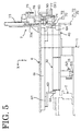
- the transferring mechanism 6 includes a movable member 62 which is provided substantially above the fixed magazine 40 and moved and positioned along the forward/backward direction X by a direct-acting positioning mechanism 61, and a pushing member 64 drivingly coupled to the movable member 62 via a support column 63 for pushing the fuses.
- the direct-acting positioning mechanism 61 may employ a known construction: e.g. it may include a direct-acting shaft movably supporting the movable member 62 along the forward/backward direction, a ball screw driven by a servo motor, a ball nut screwed onto the ball screw, etc.
- the above movable member 62 is drivingly coupled e.g. to this ball nut.
- the pushing member 64 is movable in a range defined between the front end of the fixed magazine 40 (the pushing member 64 in this state is shown in phantom in FIG. 5) and a position behind the rear end of the movable magazine 30, and passes through the respective holding chambers 35 of the movable magazine 30 and the fixed magazine 40 during its movement to thereby push the fuses in the holding chamber 35 forward.
- the pushing member 64 is positioned at the rear end of its movable range (shown in solid line in FIG. 5) before the movable magazine 30 is located at the receiving position.
- the pushing member 64 is moved forward to push the rear end of the row of the fuses in the movable magazine 30.
- the fuses are moved forward along the guide surfaces 31a of the movable magazine 30 and/or of the fixed magazine 40 while being substantially aligned in a line, and are transferred to the holding chamber 35 of the fixed magazine 40 through the inlet 35a of the fixed magazine 40.
- the pushing member 64 enters the fixed magazine 40 preferably to the degree that it does not hinder the movement of the movable magazine 30.
- the fuse transferring operation follows the fuse receiving operation.
- the pushing member 64 pushes the rear end of the row of the fuses in the fixed magazine 40, thereby causing the front end of the row of the fuses to reach the outlet 35b of the fixed magazine 40, the pushing member 64 is stopped. While the fuse is inserted by the inserting mechanism 7, there is no fuse at the outlet 35b of the fixed magazine 40. Upon reaching a timing for the preparation of the next fuse after completing the insertion by the inserting mechanism 7, the pushing member 64 is moved forward by a specified (predetermined or predeterminable) distance to push the fuse to the outlet 35b of the fixed magazine 40. The above operation is preferably continued until no more fuse is present in the fixed magazine 40.
- the above specified distance is set according to the size of the fuse inserted by the inserting mechanism 7.
- the fuse transferring operation and/or the fuse transferred to the inserting mechanism 7 is controlled by means of a control or monitoring camera (not shown).
- the monitoring camera is preferably monitoring the shape, size and/or color of the parts (e.g. the fuses) to be mounted in or on box as an example of the receiving means.
- a positioning member 74 is so provided as to substantially face the outlet 35b of the fixed magazine 40. This positioning member 74 positions the fuse with respect to the forward/backward direction X by having the fuse brought into contact with the contact or rear surface thereof.
- the rear surface of the positioning member 74 is preferably stepped such that an upper portion bulges more backward than a lower portion. The upper portion is brought into contact with the small-size fuse from the outlet 35b to locate it in a specified position so as to be received by the inserting mechanism 7. Further, the lower portion is brought into contact with the middle- or large-size fuse from the outlet 35b to locate it in a specified position so as to be received by the inserting mechanism 7.
- the inserting mechanism 7 includes a pair of holding members 70 for at least partly receiving and holding the fuse from the outlet 35b of the fixed magazine 40 therebetween, and a direct-acting positioning mechanism 73 as a vertically displacing mechanism for vertically displacing the pair of holding members 70 or for displacing the holding member 70 relatively to the box B so as to mount the fuse held therebetween in the box.
- the direct-acting positioning mechanism 73 includes, for example, an air cylinder and is capable of vertically moving an output shaft 73a of the air cylinder to locate it in a specified position in accordance with a signal from a position detector. With the output shaft 73a located in an upper position which is preferably an upper limit of its movable range, the fuse is transferred from the outlet 35b to the pair of holding members 70.
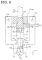
- the pair of holding members 70 include, as shown in FIG. 6, first claws 71 as a pair of first facing members, second claws 72 as a pair of second facing members, engaging mechanisms 90 for disengageably engaging the first and second claws 71, 72, and a linking mechanism 91 for linking the first claws 71 and the second claws 72 such that they can open and close with respect to each other.
- the pair of first claws 71 are held substantially between the pair of second claws 72.
- the linking mechanism 91 is comprised of a first linking member 76 for linking the upper ends of the first claws 71 and rotatably or pivotably supporting them about shafts 76a, and a second linking member 77 for linking the upper ends of the second claws 72 and rotatably or pivotably supporting them about shafts 77a.
- the first linking member 76 is relatively vertically displaceable along a hole or recess 77b formed in the second linking member 77. Further, the first linking member 76 is drivingly coupled to the output shaft 73a of the direct-acting positioning mechanism 73.
- the second linking member 77 is vertically displaceably supported on a direct-acting bearing 78, and has its upper limit of its vertical displacement range restricted by the contact of a restricting member 79 fixed to one end thereof with a fixed member 60.
- the second linking member 77 is biased downward by a compression spring 92.
- the engaging mechanism 90 is, as shown in FIG. 6, comprised of a tower surface 77h of the second linking member 77 and a stepped surface 76h of the first linking member 76 which are substantially held in (sliding) contact with each other, and pairs of slanted surfaces 71a, 72a which are respectively formed on the first and second claws 71, 72 and are held in contact with each other.
- An engaged state is achieved with both the first claws 71 and the second claws 72 closed.
- a tension spring 93 is mounted between the second claws 72 to bias the second claws 72 closer to each other by its elastic force.
- the biasing force of the tension spring 93 is also transmitted to the first claws 71 to bias them closer to each other, preferably towards a substantially closed position.
- leaf springs may be provided between the first linking member 76 and the first claws 71 so as to bias them towards a substantially closed position.
- the output shaft 73a of the direct-acting positioning mechanism 73 is drivingly coupled to the second claws 72 via the first claws 71 and the engaging mechanism 90, and the respective members are displaced as a unit.
- the engaged state is maintained by the elastic force of the tension spring 93.
- the pairs of slanted surfaces 71a, 72a are held in contact with each other without sliding along each other, and the output shaft 73a of the direct-acting positioning mechanism 73 is drivingly coupled to the second claws 72 via the first claws 71 and the engaging mechanism 90. Accordingly, the first and second claws 71, 72 are displaced as a unit while being closed. At this time, the engaged state is maintained by the elastic force of the tension spring 93. The engaged state is released to open the second claws 72 by relatively displacing the first and second claws 71, 72 while causing the pairs of the slanted surfaces 71a, 72a to slide along each other.
- the first claws 71 open the pair of second claws 72 wider apart against the elastic force of the tension spring 93 while the slanted surfaces 71a, 72a of the engaging mechanism 90 are sliding along each other, thereby releasing the engaged state. As a result, only the first claws 71 are further displaced downward with the pair of second claws 72 opened apart.
- the engaged state is achieved again when the lower surface 77h of the second linking member 77 and the stepped surface 76h of the first linking member 76 come into contact with each other. As a result, the first claws 71 and the second claws 72 are moved upward together.
- the pair of holding members 70 are formed with a plurality of, e.g. three pairs of projections 71b, 72c, 72d corresponding to the configurations of a plurality of kinds of fuses.
- Each projection is preferably in the form of a step having a recess thereabove.
- the respective pairs of projections 71b, 72c, 72d face the substantially opposite sides of the fuses and lock them by their upper surfaces or hold them by placing the flanges of the fuses on their upper surfaces.
- the plurality of pairs of projections 71b, 72c, 72d are arranged one after another along vertical direction, and a spacing between the upper pair of projections is narrower than the one between the lower pair of projections.
- the projections 71b are formed on the first claws 71, and are located in the uppermost positions among the three pairs of projections.
- the projections 71b are spaced apart by substantially the same distance as the elongated projections 31b of the fixed magazine 40 for locking the upper ends of the small-size fuses F1.
- the projections 71b include slanted surfaces 71c which are formed on their upper surfaces for locking the fuses and are curved surfaces slanted downward along the facing directions.
- the projections 72c are formed on the second claws 72, and are provided between the other two pairs of projections 71b, 72d along vertical direction.
- the projections 72c are spaced apart by substantially the same distance and cross section as the elongated projections 31c of the fixed magazine 40 for locking the upper ends of the middle-size fuses F2.
- the projections 72d are formed on the second claws 72, and are provided in the bottommost positions among the three pairs of projections 71b, 72c, 72d.
- the projections 72d are spaced apart by substantially the same distance and cross section as the elongated projections 31d of the fixed magazine 40 for locking the upper ends of the large-size fuses F3.
- the respective pairs of projections 71b, 72c, 72d are preferably provided in such positions as to avoid an interference with the fuses locked by the other pairs of projections.
- the projections 71b are located above the fuses F2, F3 locked by the projections 72c, 72d, thus, do not contact them.
- the projections 72c are located transversely more outward than the fuse F1 locked by the projections 71b while being located above the fuse F3 locked by the projections 72d, thus, do not contact them.
- the projections 72d are located transversely more outward than the fuses F1, F2 locked by the projections 71b, 72c, thus, do not contact them.
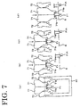
- the fuse F1 is fed from the fixed magazine 40 to between the projections 71b of the pair of holding members 70 in their upper positions by the transferring mechanism 6 (see FIG. 7(a)).
- both the first claws 71 and the second claws 72 are closed in the engaged state.
- the first and second claws 71, 72 are lowered by the direct-acting positioning mechanism 73 to reach the bottom end positions of the second claws 72 (see FIG. 7(b))
- the second claws 72 are opened (see FIG. 7(c)) preferably by the interaction of the slanted surfaces 71a, 72a (see FIG. 6).
- the bottom end positions of the second claws 72 are set such that the second claws 72 do not contact the fuse already inserted therebelow (shown as F1A in FIGS. 7(b) to 7(d)). Then, only the first claws 71 are lowered to push the fuse F1 into a box by a specified (predetermined or predeterminable) engagement length (see FIG. 7(d)). Thereafter, the first claws 71 are moved upward or away from the box B. At this stage, the first claws 71 are automatically opened to release the fuse while the slanted surfaces 71c of the projections 71 are sliding along a flange of the fuse. In this way, the slanted surfaces 71c function as means for opening the first claws 71. The first and second claws 71, 72 are returned to their upper positions.
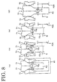
- the fuse F2 is fed from the fixed magazine 40 to between the projections 72c of the pair of holding members 70 in their upper positions by the transferring mechanism 6 (see FIG. 8(a)).
- both the first claws 71 and the second claws 72 are substantially closed in the engaged state.
- the fuse F2 is pushed by upper portions 72e of the projections 72c of the second claws 72 and the projections 71b located at the bottom ends of the first claws 71 to be partly inserted into the box B (see FIG. 8(b)).
- partial insertion refers to a state where the fuse is inserted by a length shorter than the specified engagement length.
- the engaged state is released, whereupon the first claws 71 held closed push the partly inserted fuse F2 while the second claws 72 are opened (see FIG. 8(c)), and continue to push the fuse F2 until the fuse F2 is inserted by the specified engagement length (see FIG. 8(d)).
- the first and second claws 71, 72 are returned to their upper positions as the first claws 71 are moved upward or away from the box B.
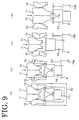
- the fuse F3 is fed from the fixed magazine 40 to between the projections 72d of the pair of holding members 70 in their upper positions by the transferring mechanism 6 (see FIG. 9(a)).
- both the first claws 71 and the second claws 72 are substantially closed in the engaged state.
- the fuse F3 is pushed by the projections 72c located above the projections 72d of the second claws 72 to be partly inserted into the box B (see FIG. 9(b)).
- a reaction force immediately acts on the second claws 72.
- the engaged state is maintained in the meanwhile.
- the second claws 72 can push the fuse F3, though only by a short length.
- the second claws 72 having partly inserted the fuse F3 does not contact the already inserted fuse (shown as F3A in FIGS. 9(b) to 9(d)). If the insertion is further continued, the second claws 72 have their movements restricted upon being subject to the upward acting reaction force from the fuse F3, whereas the first claws 71 continue to be moved downward. As a result, the engaged state is released to open the second claws 72 (see FIG. 9(c)).
- first claws 71 pushes the upper end of the partly inserted fuse F3 into the box until the fuse F3 is inserted by the specified engagement length (see FIG. 9(d)). Consequently, the first and second claws 71, 72 are returned to their upper positions as the first claws 71 are moved upward or away from the box B.
- the upper end of the fuse is pushed by the first claws 71 after being partly inserted by the second claws 72.
- the second claws 72 may not be lowered by a sufficient distance without contacting the fuses already inserted in the box located around the second claws 72. Even in such a case, the second claws 72 do not contact the already inserted fuses around them if the fuse is only partly inserted. Further, if the fuse is partly inserted, it can be securely inserted by the first claws 71 without being inclined only by having its upper end pushed.
- the moving mechanism 8 is, as shown in FIG. 1, adapted to horizontally move the box with respect to the transferring mechanism 6, the inserting mechanism 7 and the like secured to the frame 11, and includes a pair of direct-acting positioning mechanisms 81, 82.
- the positioning mechanisms 81, 82 may employ a known construction similar to the aforementioned positioning mechanisms, and are so arranged that their moving directions are orthogonal to each other. Accordingly, a movable member 83 provided atop or on the positioning mechanism 82 can be positioned by being moved in two horizontal directions.
- the box is positioned and detachably mounted on the movable member 83.
- fuses having different configurations can be mounted using one fixed magazine 40 and one pair of holding members 70.
- the fuse when being fed out through the outlet 35b of the fixed magazine 40 by the transferring mechanism 6, the fuse is received between the pair of holding members 70 and held by being placed on the pair of projections corresponding thereto, for example, on the projections 71b in the case of the small-size fuse F1. If the pair of holding members 70 are displaced downward by the direct-acting positioning mechanism 73, the fuse can be mounted in the box.
- the inventive assembling apparatus can be made smaller than the conventional assembling apparatuses which require a plurality of each of the above members and mechanisms.
- the projections may be only spaced apart by a predetermined distance. Accordingly, the holding construction and the mechanism for opening and closing the pair of holding members 70 can be more simplified as compared to the case where the fuse is held by clamping. Particularly, a construction for opening and closing the holding members 70 such as an air cylinder can be omitted in this embodiment since the holding members 70 are automatically opened and closed.
- the relatively displaceable first and second claws 71, 72 are made displaceable as a unit by the engaging mechanism 90, and the second claws 72 are opened by the relative displacement of the pair of slanted surfaces 71a, 72a of the engaging mechanism 90.
- the fuse can be inserted into the box using the projections of the respective closed claws.
- the second claws 72 are subjected to an upward acting reaction force and are displaced from the first claws 71.
- the second claws 72 are opened by the pair of slanted surfaces 71a, 72a as a means for opening the second claws 72 to automatically release the second claws 72, with the result that the construction for opening the second claws 72 can be simplified. Further, since the first and second claws 71, 72 are displaced with respect to each other if, for example, the downward displacement of the second claws 72 is restricted when the small-size fuse locked by the projections 71b of the first claws 71 is to be inserted into the box, only the first claws 71 can be displaced downward while the second claws 72 are opened. As a result, the second claws 72 are unlikely to stand as a hindrance during the insertion of the small-size fuse. Therefore, fuses having different sizes can be easily handled.
- the projections 71b are formed with the slanted surfaces 71c
- the slanted surfaces 71c are relatively displaced upward while the fuse remains mounted. According to their relative upward displacement, the slanted surfaces 71c are subjected to a reaction force while sliding along the flange of the fuse, thereby automatically spacing the projections 71b wider apart to eventually release the fuse and move upward. This obviates the need to adjust the spacing of the projections 71b according to the size of the fuse. As a result, the construction for releasing fuse can be simplified.
- the spacing between the pair of lower projections is set wider than the one between the pair of upper projections, the respective projections can be easily arranged when the lower projections are used for large-size fuses and the upper projections are used for small-size fuses.
- the wider the spacing between the pair of projections 71b, 72c or 72d the lower the pair of projections 71b, 72c or 72d are provided.
- the larger the fuse the lower it is held.
- the pair of holding members 70 can be preferably used for handling fuses having different configurations.
- the pair of holding members 70 are movable only along vertical direction in the foregoing embodiment, they may be movable along horizontal direction.
- the assembling apparatus can be made smaller since a plurality of fuses having different configurations can be handled using the parts holding member and the pair of holding members.
- the construction for opening the second facing members can be simplified since the second facing members are opened, taking advantage of the relative displacement of the first and second facing members of the pair of holding members. Further, the second facing members are unlikely to stand as a hindrance when small-size fuses are handled. Thus, fuses having different sizes can be easily handled.
- the construction for releasing the fuse can be simplified since the fuse can be automatically released by the slanted surfaces of the locking portions.
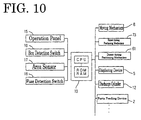
- the assembling apparatus 1 is or may be also provided with the controller 10 as a control means for operating the respective elements described above.
- the controller 10 includes, as shown in a block diagram of FIG. 10, a microcomputer (CPU) as a control center, a ROM and RAM for storing a program, etc.
- the CPU controls the respective elements in accordance with the program.
- an operation panel 15 for inputting an operation start command, the type of the fuse box to be assembled, etc.
- a box detection switch 16 for outputting a signal when the box is set on the moving mechanism 8
- an area sensor 17 provided around or corresponding to the movable member 83 of the moving mechanism 8 when being moved forward for detecting a hand of an operator or like obstacle near the moving mechanism 8
- a fuse or part detection switch 18 for outputting a signal representing the presence or absence of the fuse and/or of the electric/electronic part at the outlet 35b of the fixed magazine 40, and the like.
- the cylinders, the motors, the valves and the testing device of the aforementioned units and mechanisms are connected to the controller 10 via driving circuits (not shown).
- This assembling apparatus 1 can assemble a plurality of e.g. fuse boxes which come in a plurality of types.
- the same type of fuse boxes may be continuously assembled or a plurality of types of fuse boxes may be successively assembled.
- a case where a plurality of fuse boxes of the same type are continuously assembled is mainly described below.
- a plurality of fuses are necessary to assemble one fuse box.
- a set of fuses comprised of these plurality of fuses are held in the fixed magazine 40 in the assembling apparatus 1. This set of fuses are also accommodated in the movable magazine 30.
- Step S1 a judgment is made as to whether or not the box has been set based on a detection result of the box detection switch 16. Subsequently, when the operation of the moving mechanism 8 is judged to be safe based on a detection result of the area sensor 17, the movable member 83 is moved to a position right below the inserting mechanism 7 by the moving mechanism 8.
- the controller 10 causes the displacing unit 5 to displace the movable magazine 30 to the respective feeding positions to collect a set of necessary fuses in the movable magazine 30, which fuses are fed through the outlets 2a of the parts feeding units 2 (Steps S2 to S6). Simultaneously with this fuse collecting operation, the fuses are mounted by the mounting unit 4 (Steps S11 and S12).
- the set of fuses necessary for the fuse box of the type being assembled are normally collected in the movable magazine 30 (Step S4).
- the movable magazine 30 is moved to the parts feeding units 2 for feeding the necessary fuses in a specified order in which the fuses are mounted by the mounting unit 4, and receives the fuses.
- the fuses are inserted into the movable magazine 30 from the respective parts feeding units 2 in accordance with the predetermined or predeterminable mounting order and are aligned in a chronological order, i.e. in an order corresponding to their successive mounting in the box B.
- Step S2 of FIG. 11 which is a planned number of fuse boxes to be assembled minus a number of already assembled fuse boxes is 1
- Step S3 a remaining number which is a planned number of fuse boxes to be assembled minus a number of already assembled fuse boxes is 1
- Step S4 a set of fuses for the fuse box of the type being presently assembled are collected in the movable magazine 30 as described above (Step S4).
- Step S6 If the fuse is still present in the fixed magazine 40 when the remaining number is 1 (NO in Step S2, NO in Step S3), whether or not assembling of a next fuse box is planned is judged. If assembling of the next fuse box is planned, a set of fuses for the fuse box to be assembled next are collected in the movable magazine 30 (Step S6).
- the fuse mounting operation is performed in the mounting unit 4 simultaneously with the fuse collecting operation. Since the fuses are normally held in the fixed magazine 40 (NO in Step S11), the fuse mounting operation is started simultaneously with the start of the fuse collecting operation. The fuses are inserted one by one from the front in accordance with the order held in the fixed magazine 40 (Step S12). Upon completion of assembling, the fuses in the fixed magazine 40 are used up to thereby empty the fixed magazine 40.
- Step S7 If the fixed magazine 40 is emptied (YES in Step S7) and the fuse collecting operation in Steps S4, S6 is completed, a group of fuses in the movable magazine 30 are transferred to the fixed magazine 40 by the transferring mechanism 6 of the mounting unit 4 while maintaining their aligned order (Step S8). During this time, the moving mechanism 8 moves the movable member 83 forward to replace the assembled fuse box by a box to be assembled.
- Step S8 Upon completion of transfer in Step S8, the fuse collecting operation is performed to collect a specified set of fuses in the movable magazine 30. Upon completion of replacement of the box in the moving mechanism 8, the fuse mounting operation is performed in the mounting unit 4 in a manner similar to the above.
- Step S12 the fuse mounting operation is started (Step S12) after the fuses collected in the movable magazine 30 by the fuse collecting operation are transferred to the fixed magazine 40 (NO in Steps S8, S11). At least partially simultaneously with this fuse mounting operation, the aforementioned fuse collecting operation is performed again.
- the fuse collecting operation for the next fuse box can be performed at least partly simultaneously with the fuse mounting operation for the fuse box presently being assembled.
- the fuses collected in the movable magazine 30 can be transferred to the fixed magazine 40 preferably at once by the transferring mechanism 6 of the mounting unit 4, the pause of the mounting unit 4 for the preparation of parts can be suppressed to a minimum. As a result, quick assembling can be realized, thereby shortening, for example, a tact time.
- quick assembling is achieved by an improvement of the operation efficiency (a ratio of a time required for the fuse mounting operation to an operation time including a paused time for the preparation of parts) of the mounting unit 4, and the construction of the assembling apparatus 1 can be simplified since it is not necessary to provide many mounting units 4 and displacing units 5.
- the assembled fuse box can be taken out simultaneously while the fuses are transferred to the fixed magazine 40 by the mounting unit 4, it is not necessary to allot time only for the fuse transferring operation. As a result, a tact time can be further shortened. Furthermore, since the fixed magazine 40 and the movable magazine 30 can feed a plurality of different fuses in the specified order, it is sufficient to provide only one each of them instead of installing them for the respective kinds of the fuses. This brings about a higher degree of freedom in arrangement and realizes space-saving. As a result, the fuses can, for example, be fed in proximity to where the fuses are mounted in the box. Therefore, the fuse box can be even more quickly assembled.
- the displacing unit 5 displaces the movable magazine 30 which is lighter than other units, it is allowed to have a simple construction and a load can be reduced. As a result, the movable magazine 30 can be displaced at a high speed and a time required to collect the fuses can be shortened.
- the assembling apparatus 1 mounts the fuses from a plurality of parts feeding units 2 by means of the single inserting mechanism 7, the construction thereof can be simplified. Further, since the tact time can be shorted and the number of products in process can be reduced, the types of the fuse boxes can be quickly switched.
- the fuses mounted in the box are narrowly spaced from each other and need to be inserted by being pushed.
- the fuses can be securely inserted by the inserting mechanism 7 highly rigidly secured to the frame 11.
- the fuses can be securely fed to the inserting mechanism 7 from the fixed magazine 40.
- the fuses are tested by the testing devices of the parts feeding units 2 immediately before being collected in the movable magazine 30 and only the fuses having a satisfactory test result are collected in the movable magazine 30. Accordingly, there is no likelihood of inserting defective fuses.
- the inserting mechanism 5 7 and the fixed magazine 40 are secured to the frame 11 as described above, possibilities of insertion and feed errors into the fuse box can be reduced. This is because the fuse mounting operation cannot be resumed if there is a defective fuse or an insertion error since only a specified number of different fuses are fed in the movable magazine 30 and the fixed magazine 40.
- this embodiment is free from such an undesirable event.
- the movable magazine 30 is separately provided with the inlet 35a at its rear end and the outlet 35b at its front end, one opening may be used both as the inlet 35a and as the outlet 35b.
- a specified set of fuses are collected in the movable magazine 30 for one fuse box in the foregoing embodiment, the present invention is not limited thereto.
- a plurality of sets of fuses may be collected at once for a plurality of fuse boxes or a set of fuses may be collected in a plurality of times for one fuse box.
- the constructions and relative arrangement of a plurality of parts feeding units 2, the movable magazine 30 and the inserting mechanism 7 are not limited to the aforementioned ones. It is sufficient to construct and relatively arrange the respective elements such that the fuses are fed from the fixed parts feeding units 2 to the inserting mechanism 7 via the displaceable movable magazine 30 to be inserted into the box.
- the pause of the mounting unit for the preparation of parts can be suppressed.
- a tact time can be shortened.
- the construction of the assembling apparatus can be simplified since it is sufficient to provide only one mounting unit, one transferring mechanism, one fixed magazine, etc.
- the tact time can be even more shortened.
Landscapes
- Fuses (AREA)
Abstract
Description
- The present invention relates to an assembling apparatus, in particular to a fuse box assembling apparatus, for mounting a plurality of electric and/or electronic parts, in particular fuses in a receiving member such as a box and/or a board, in particular to assemble a fuse box used, for example, in an automotive vehicle. Furthermore, the present invention relates to an assembling method, in particular to a fuse box assembling method.
- In particular, the aforementioned fuse box is such that a plurality of fuses as parts are mounted in a box as a base. The fuses to be inserted come in a plurality of kinds having different sizes and configurations.
- The following is known, for example, as a fuse box assembling apparatus. This assembling apparatus is provided with a plurality of parts feeder provided for the respective kinds of fuses for successively feeding fuses, and an inserting unit for taking out the fuses one by one from the respective parts feeder and inserting them into a box. The inserting unit includes a clamping device for clamping the fuse and an arm mechanism for moving the clamping device between the respective parts feeders and the box. In the assembling apparatus, the respective parts feeders are arrayed side by side at one end thereof, whereas the box is provided at the other end thereof. One fuse is selected from each parts feeder, taken out by the inserting unit, conveyed from the one end of the assembling apparatus to the other end thereof, and inserted into the box. After a series of these operations are repeated for all fuses, assembling of the fuse box is completed.
- However, in the above fuse box assembling apparatus, the fuse is taken out from the respective parts feeders every time the fuse is to be inserted. It takes time and the fuse inserting operation cannot be performed while the clamping device moves between the parts feeders and the box. As a result, a tact time for assembling one fuse box tends to be longer.
- In order to realize a shorter tact time, there may be considered a fuse box assembling apparatus in which a combination of the parts feeder and the inserting unit is provided for each kind of fuses, and a multitude of these combinations are arrayed in a line according to the fuses to be mounted. However, such an assembling apparatus is large and complicated. Further, since there are many products in process, it is difficult to quickly switch the kinds of fuse boxes when many kinds of fuse boxes are manufactured.
- The above fuse box is assembled by inserting a plurality of fuses into a box, and these fuses come in a plurality of kinds having different sizes and configurations.
- A fuse box assembling apparatus is provided with parts feeders provided for the respective kinds of fuses for successively feeding the fuses along transport rails, and inserting units for receiving the fuses one by one from the parts feeders and inserting them into a box. Each inserting unit includes clamping hands for clamping the fuse and an arm mechanism for moving the clamping hands between the corresponding parts feeder and the box.
- If the configurations of the fuses differ, the configurations of the transport rails of the parts feeder and the configurations and opening amount of the clamping hands may need to be differed. As a result, an insertion station constructed by the parts feeder and the inserting unit is provided for each kind of the fuses and specially used therefor.
- However, the assembling apparatus tends to become larger if the parts feeder and the inserting unit are specially provided for each kind of the fuses.
- The present invention was developed to solve the above technical problem, and an object thereof is to provide an assembling apparatus and an assembling method which allow to easily mount a plurality of electric and/or electronic parts, in particular which can quickly mount a plurality of different kinds of fuses despite its simple construction.
- This object is solved according to the invention by an assembling apparatus according to
claim 1 or 7 and by an assembling method according toclaim - According to the invention, there is provided an assembling apparatus for mounting a plurality of electric/electronic parts, preferably fuses in or on or at a receiving member, preferably in or on a box and/or on a board, in particular an electric or electronic board, comprising:
- a fixed mounting unit including a first parts holding member for holding a plurality of parts necessary to assemble a receiving member in an order that they are mounted in the receiving member and adapted to successively mount the plurality of parts held by the first parts holding member in the receiving member,
- a second parts holding member which is movable between one or more feed positions, where the parts are (semi-) automatically fed to the second parts holding member and a position corresponding to the mounting unit, holds a plurality of parts in the order that they are mounted, receiving and holding the parts fed, and is then moved to the position corresponding to the mounting unit, and
- a transferring mechanism for transferring the plurality of parts held by the second parts holding member at once to the first parts holding member of the mounting unit when the second parts holding member comes to the position corresponding to the mounting unit.
-
- According to a preferred embodiment of the invention, the apparatus further comprises a plurality of fixed parts feeding units, each including a parts chamber for at least partly accommodating a specified kind of parts, preferably of fuses, and a feeding mechanism for successively feeding the accommodated parts.
- Further preferably, the second parts holding member is movable between positions substantially facing the respective parts feeding units and a position substantially facing the mounting unit, holds a plurality of parts in the order that they are mounted by being moved successively to the positions substantially facing the parts feeding units accommodating the parts necessary to assemble the receiving member, receiving and holding the parts fed from the parts feeding units, and is then moved to the position substantially facing the mounting unit.
- According to a further preferred embodiment of the invention, there is provided a fuse box (or board) assembling apparatus for mounting a plurality of fuses in a box, comprising:
- a plurality of fixed parts feeding units, each including a fuse chamber for accommodating a specified kind of fuses and a feeding mechanism for successively feeding the accommodated fuses,
- a fixed mounting unit including a holding means for holding a plurality of fuses necessary to assemble a fuse box in an order that they are mounted in the box and adapted to successively mount the plurality of fuses held by the holding means in the box,
- a parts holding member which is movable between positions facing the respective parts feeding units and a position facing the mounting unit, holds a plurality of fuses in the order that they are mounted by being moved successively to the positions facing the parts feeding units accommodating the fuses necessary to assemble the fuse box, receiving and holding the fuses fed from the parts feeding units, and is then moved to the position facing the mounting unit, and
- a transferring mechanism for transferring the plurality of fuses held by the parts holding member at once to the holding means of the mounting unit when the parts holding member comes to the position facing the mounting unit.
-
- With the above construction, a specified number of fuses are collected in the parts holding member from the respective parts feeding units for one fuse box, and are transferred to the mounting unit at once to be mounted.
- Further, in the case of assembling a plurality of fuse boxes, a fuse collecting operation for a fuse box to be assembled next is performed simultaneously with a fuse mounting operation for the fuse box being assembled. In addition, the collected fuses can be transferred at once to the mounting unit by the transferring mechanism. As a result, the pause of the mounting unit for the preparation of parts can be suppressed, thereby shortening a tact time.
- Furthermore, the construction of the fuse box assembling apparatus can be simplified since it is not necessary to provide many mounting units, transferring mechanisms and parts holding members.
- Preferably, the parts holding member is moved to the positions corresponding to or substantially facing the plurality of parts feeding units in a specified sequence to receive and hold a plurality of parts or fuses in the order that they are to be mounted while the mounting unit is at least partly mounting the parts or fuses in the receiving member, preferably in the box.
- With this construction, a plurality of fuses to be mounted next can be securely collected in the parts holding member, a tact time can be even more shortened.
- According to the invention, there is further provided an assembling method for mounting a plurality of electric/electronic parts, preferably fuses in or on or at a receiving member, preferably in or on a box and/or in or on a (electri/electronic) board, comprising:
- holding a plurality of parts necessary to assemble a receiving member in an order that they are mounted in the receiving member by means of a first parts holding member of a fixed mounting unit being adapted to successively mount the plurality of parts held by the first parts holding member in the receiving member;
- (semi-) automatically feeding the parts to a second parts holding member;
- moving the second parts holding member holding the plurality of parts in the order that they are mounted to a position corresponding to the mounting unit; and
- transferring the plurality of parts held by the second parts holding member at once to the first parts holding member of the mounting unit by means of a transferring mechanism, when the second parts holding member comes to the position corresponding to the mounting unit.
-
- According to a preferred embodiment of the invention, the step of moving the second parts holding member to the position(s) where the plurality of parts feeding units is at least partially performed at the same time with the step of at least partly mounting the parts in the receiving member by means of the mounting unit.
- According to the invention, there is further provided an assembling apparatus, in particular according to the above described invention or embodiments, for mounting a plurality of kinds of electric/electronic parts, preferably of fuses, having different configurations in or on or at a receiving member, preferably in or on a box and/or in or on a (electric/electronic) board, comprising:
- a parts holding member for holding a plurality of parts necessary to assemble a receiving member while substantially aligning or arranging them in an order that they are to be mounted,
- a transferring mechanism for successively feeding the plurality of parts held by the parts holding member through an outlet of the parts holding member,
- a pair of holding members which are provided at the substantially opposite sides of the part at the outlet in such a manner as be opened and closed with respect to each other for receiving the parts fed by the transferring mechanism to mount them in the receiving member,
- at least one pair of locking portions which are provided on the pair of holding members so as to be substantially opposed to each other, and
- a vertically displacing mechanism for vertically displacing the pair of holding members (or moving the holding members along a direction towards the receiving member) between an upper position where the holding members substantially face the outlet of the parts holding member and a lower position corresponding to a state where the part is at least partly mounted in the receiving member.
-
- According to a preferred embodiment, the at least one pair of locking portions have a steplike shape comprised of a recessed upper portion and a projecting lower portion in such a manner as to correspond to the plurality of parts, and on which projected portions formed at upper portions of side surfaces of the parts are placeable when the pair of holding members are closed with respect to each other.According to a further preferred the invention, there is provided a fuse box assembling apparatus for mounting a plurality of kinds of fuses having different configurations in a box, comprising:
- a parts holding member for holding a plurality of fuses necessary to assemble a fuse box while aligning them in an order that they are mounted,
- a transferring mechanism for successively feeding the plurality of fuses held by the parts holding member through an outlet of the parts holding member,
- a pair of holding members which are provided at the opposite sides of the fuse at the outlet in such a manner as be opened and closed with respect to each other for receiving the fuses fed by the transferring mechanism to mount them in the box,
- at least one pair of locking portions which are provided on the pair of holding members so as to be opposed to each other and have a steplike shape comprised of a recessed upper portion and a projecting lower portion in such a manner as to correspond to the plurality of fuses, and on which projected portions formed at upper portions of side surfaces of the fuses are placeable when the pair of holding members are closed with respect to each other, and
- a vertically displacing mechanism for vertically displacing the pair of holding members between an upper position where the holding members face the outlet of the parts holding member and a lower position corresponding to a state where the fuse is mounted in the box.
-
- With this construction, the fuse fed through the outlet by the transferring mechanism is received between the pair of holding members and held by being placed on the pair of locking portions corresponding thereto. The fuse can be mounted in the box when the pair of holding members are displaced downward by the vertically displacing mechanism.
- Since the pair of holding members are constructed such that the projected portion of the fuse is placed on the pair of locking portions with the holding members closed, it is sufficient to form the locking portions which are spaced apart by a specified distance. Thus, as compared to a case where the fuse is clamped, a construction for holding the fuse can be simplified.
- Since both the parts holding member and the pair of holding members can handle a plurality of kinds of fuses, it is sufficient to provide one each of the parts holding member, the pair of holding members, and other associated mechanisms including the vertically displacing mechanism. Therefore, the inventive assembling apparatus can be made smaller than the conventional assembling apparatuses which require a plurality of each of the above members and mechanisms.
- Further preferably, the pair of holding members comprise:
- a pair of first facing members which are coupled to the vertically displacing mechanism and can be opened and closed with respect to each other,
- a pair of second facing members which are so provided at the opposite sides of the pair of first facing members as to be opened and closed with respect to each other, and is vertically displaceable with respect to the pair of first facing members, and preferably
- an engaging mechanism for engaging the first and second facing members so as to restrict a relative displacement thereof, wherein the engaging mechanism includes a pair of slanted surfaces which are provided between the first and second facing members and can be held in sliding contact with each other, the first and second facing members being displaced as a unit by holding the pair of slanted surfaces in contact with each other while preventing their relative sliding movements, the second facing members being opened by displacing the first and second facing members with respect to each other while causing the pair of slanted surface to slide along each other, and the first and second facing members further preferably having a pair of locking portions, respectively, the locking portions of the first facing member being located above and being more narrowly spaced apart than those of the second facing member.
-
- With this construction, the respective pairs of locking portions can be easily arranged using the pair of locking portions of the second facing members for large-size fuses while using those of the first facing members for small-size fuses.
- By holding the slanted surfaces of the engaging mechanism in contact with each other while preventing their relative sliding movements, the first and second facing members can be displaced downward as a unit and the corresponding fuses can be inserted into the box using the respective pairs of locking portions. At this time, when the fuse locked by the locking portions of the second facing members is inserted into the box, the second facing members are subjected to an upward acting reaction force, and the first and second facing members are vertically displaced with respect to each other while the slanted surfaces are sliding along each other. Accordingly, the second facing members can be automatically opened to release the fuse. Further, if the first and second facing members are vertically displaced with respect to each other when the fuse locked by the locking portions of the first facing members is inserted into the box, only the first facing members can be displaced downward while opening the second facing members. As a result, the second facing members are unlikely to stand as a hindrance.
- Most preferably, in the fuse box assembling apparatus, the pair of locking portions have slanted surfaces, which are slanted downward in facing directions, on its portion where the part or fuse is placed.
- With this construction, if the holding members are displaced upward after the fuse is mounted in the box, the slanted surfaces of the locking portions are automatically spaced apart wider along the mounted fuse to release the fuse without displacing this fuse.
- According to the invention, there is further provided an assembling method, in particular according to the above described invention or embodiments, for mounting a plurality of kinds of electric/electronic parts, preferably of fuses, having different configurations in or on or at a receiving member, preferably in or on a box and/or in or on a (electric/electronic) board, comprising:
- holding a plurality of parts necessary to assemble a receiving member by means of a parts holding member while substantially aligning or arranging them in an order that they are to be mounted,
- successively feeding the plurality of parts held by the parts holding member by means of a transferring mechanism through an outlet of the parts holding member,
- receiving the parts fed by the transferring mechanism by means of a pair of holding members which are provided at the substantially opposite sides of the part at the outlet in such a manner as be opened and closed with respect to each other to mount them in the receiving member, and
- vertically displacing the pair of holding members (or moving them towards and away from the receiving member) by means of a vertically displacing mechanism between an upper position where the holding members substantially face the outlet of the parts holding member and a lower position corresponding to a state where the part is at least partly mounted in the receiving member.
-
- According to a further preferred embodiment, the holding members are opened to discharge the part in the receiving member and wherein the holding members are vertically displaced while being substantially closed, so as to at least partly mount the part in the receiving member.
- Preferably, the part is at least partly mounted by means of first holding members being substantially closed while being discharged by the opening of second holding members, the first holding member pushing the part from above upon being vertically displaced.
- These and other objects, features and advantages of the present invention will become apparent upon a reading of the following detailed description and accompanying drawings in which:
- FIG. 1 is a perspective view of a fuse box assembling apparatus according to one embodiment of the invention,
- FIG. 2 is a perspective view of a parts feeding unit shown in FIG. 1,
- FIG. 3 is a perspective view of a movable magazine and/or fixed magazine shown in FIG. 1,
- FIG. 4 is a front view of the movable magazine and/or fixed magazine shown in FIG. 1,
- FIG. 5 is a side view of an inserting mechanism and the movable magazine and/or fixed magazine shown in FIG. 1,
- FIG. 6 is a front view showing an essential portion of the inserting mechanism shown in FIG. 1,
- FIGS. 7(a) to 7(d) are diagrams showing an operation sequence of the inserting mechanism shown in FIG. 6 when a small-size fuse is inserted,
- FIGS. 8(a) to 8(d) are diagrams showing an operation sequence of the inserting mechanism shown in FIG. 6 when a middle-size fuse is inserted,
- FIGS. 9(a) to 9(d) are diagrams showing an operation sequence of the inserting mechanism shown in FIG. 6 when a large-size fuse is inserted,
- FIG. 10 is a block diagram of a controller of the fuse box assembling apparatus of FIG. 1, and
- FIG. 11 is a flow chart showing contents of a control of the fuse box assembling apparatus of FIG. 1. One embodiment of the invention is described in detail with reference to the accompanying drawings. In the following, the invention is disclosed with reference to an apparatus for mounting a fuse box. However, it should be understood that the invention may be applied also to apparatuses and methods for mounting other electric and/or electronic parts in a receiving member such as a box and/or a board (e.g. an electric or electronic board). FIG. 1 is a schematic perspective view showing a fuse box assembling apparatus according to this embodiment of the invention. It should be noted that arrows X, Y, Z indicating a forward/backward direction, a transverse direction and a vertical direction, respectively, are shown in FIG. 1 and others to be described later, if necessary.
-
- The electrical/electronic part and/or fuse box assembling apparatus (hereinafter,assembling apparatus") 1 is for mounting a plurality of fuses in a box. The fuses come in a plurality of kinds having different sizes and configurations. In the following reference is made only to fuses. However, it should be understood that any other electric and/or electronic part or device such as capacitors, relays, resistors, transistors, wires, wiring boards, busbars, chips, etc. may be mounted in the box according to a preferred embodiment of the invention.

- The assembling apparatus 1 is provided with a plurality of
parts feeding units 2 for feeding fuses at a specified timing, amovable magazine 30 as a parts holding member which is movably or displaceably provided so as to receive the fuses from theparts feeding units 2 and holds a plurality of fuses, a mountingunit 4 for preferably transferring the fuses from themovable magazine 30 to a fixedmagazine 40 and successively mounting the transferred fuses in a box by means of an insertingmechanism 7, a moving or displacingunit 5 for moving or displacing themovable magazine 30 to the mountingunit 4 so that the fuses from the respectiveparts feeding units 2 can be transferred to the mountingunit 4, a controller 10 (see FIG. 10) for controlling the aforementioned respective units and mechanism, and aframe 11 on which the aforementioned respective units and mechanism are mounted or mountable. Adischarge cylinder 12 for discharging the fuses from themovable magazine 30 and acontainer 13 for containing the fuses discharged from thedischarge cylinder 12 are also provided on theframe 11. - In the assembling apparatus 1, the fuses are fed from the respective
parts feeding units 2 for each of the respective kinds. In eachparts feeding unit 2, a plurality of fuses are fed along atransport rail 21a from aparts feeder 21 while being aligned, and are pushed out one by one throughoutlets 2a bycylinders 23. The respectiveparts feeding units 2 are arranged at an angle different from 0° or 180°, preferably substantially transversely arranged with respect to a main direction of a movingmechanism 8 to be described later, the respectiveparts feeding units 2 being arranged substantially side by side at a lateral or rear part of theframe 11 and each haveoutlets 2a in two positions. Theseoutlets 2a are open forward, and transversely juxtaposed substantially at the same height. A space for displacing themovable magazine 30 is provided right in front of therespective outlets 2a. - The
movable magazine 30 is transversely moved by the displacingunit 5 to be located in a specified position. The displacingunit 5 includes, for example, a toothed pulley driven by a stepped motor, atoothed belt 52 meshable with thetoothed pulley 51, a connecting member 54 drivingly coupled to thetoothed belt 52, and a direct-actingbearing 53 for guiding the connecting member 54, thereby constructing a direct-acting positioning mechanism. When themovable magazine 30 stops right in front of theoutlets 2a of oneparts feeding unit 2, one fuse is pushed out through theoutlet 2a to enter themovable magazine 30 through an inlet at the corresponding or facing or rear end. Subsequently, themovable magazine 30 is displaced to stop right in front of or in a position corresponding to theoutlet 2a of an otherparts feeding unit 2. Then, an other fuse enters themovable magazine 30 through theoutlet 2a of this otherparts feeding unit 2, thereby pushing the one fuse already located in themovable medicines 30 forward. If the above operations are repeated in a predetermined sequence for the respective fuses, a plurality of fuses necessary to assemble one fuse box are held in themovable magazine 30 while being substantially aligned in a line substantially along the forward/backward direction in a specified order. - When the necessary fuses are collected in the
movable magazine 30, themovable magazine 30 is displaced such that the outlet at the front end of themovable magazine 30 faces or substantially corresponds to an inlet at the rear end of the fixedmagazine 40 of the mountingunit 4. The fuses are transferred forward (a direction opposite from the direction X) at once from themovable magazine 30 to the fixedmagazine 40 by atransferring mechanism 6 of the mountingunit 4 while maintaining their order of alignment. - In the mounting
unit 4, the fuses are successively fed one by one through the outlet at the front end of the fixedmagazine 40 by thetransferring mechanism 6, and are inserted into the box by the insertingmechanism 7. Simultaneously, the box is positioned in a specified position along horizontal direction by a movingunit 8. In this way, the respective fuses are or can be inserted in the specified positions of the box, and the box is pulled to a detachment position at front by the movingunit 8 when the insertion of the necessary fuses is completed, and is replaced by a box to be assembled next. - In this embodiment, the fuses necessary to assemble a next box are collected in the
movable magazine 30 while the fuses are inserted into the box being assembled by the mountingunit 4. Thus, a tact time required for assembling can be shortened. - In this embodiment, it is designed to make the assembling apparatus smaller and to enable the insertion of a plurality of fuses having different configurations into a box by the fixed
magazine 40 of the mountingunit 4 and a pair of holdingmembers 70 of the insertingunit 7. - Hereafter, the respective units or elements are described in detail.
- As shown in FIGS. 1 and 2, each
parts feeding unit 2 includes a so-calledparts feeder 21 for feeding the fuses and/or the electric/electronic parts substantially along atransport rail 21a while successively aligning them in a predetermined orientation, an accommodatingmember 22 provided at the rear end of thetransport rail 21a for receiving and accommodating the fuses to be moved to either one of theoutlets 2a, and twocylinders 23 as a mechanism for feeding the fuses out through therespective outlets 2a. In the accommodatingmember 22, fuseaccommodating chambers member 22 can be transversely moved by acylinder 24, so that the fuse accommodated in the rightfuse accommodating chamber 22a can be moved to theright outlet 2a while the fuse accommodated in the leftfuse accommodating chamber 22b can be moved to theleft outlet 2a. A testing device (not shown) for testing the fuse held at the rear end of thetransport rail 21 a is also provided. The testing device tests whether or not the fuse is electrically conductive or whether the corresponding electric/electronic part is correctly functioning by vertically moving aprobe 26 by acylinder 27 thereby contacting the fuse and/or the electric/electronic part. - In the
parts feeding unit 2, the fuse is received by coming into contact with acontact surface 21b upon reaching the rear end of thetransport rail 21a, and tested by the testing device. One tested fuse is so arranged as to substantially face one of theoutlets 2a by the accommodatingmember 22. If the above test result is satisfactory, the fuse facing theoutlet 2a is pushed by thecylinder 23 provided behind in synchronism with the facing timing of themovable magazine 30 with respect to theoutlet 2a, thereby being caused to enter themovable magazine 30 substantially facing theoutlet 2a. - As shown in FIGS. 3 and 4, the
movable magazine 30 and/or the fixedmagazine 40 include(s) a pair of facingmembers 31, and a connectingmember 32 connecting the bottom ends of the facingmembers 31. The pair of facingmembers 31 are arranged substantially side by side, and a holdingchamber 35 for holding the fuses is defined therebetween. The holdingchamber 35 has such a size as to accommodate a specified (predetermined or predeterminable) number of fuses, and holds fuses having different configurations in alignment along the forward/backward direction. These fuses are necessary to assemble a fuse box and are aligned in an order that they are mounted in the box. Aguide surface 31a is formed at a portion of each facingmember 31 which serves as an inner surface of the holdingchamber 35. Aninlet 35a is open at the rear end of the holdingchamber 35, and the fuses can enter the holdingchamber 35 through theinlet 35a and be moved along the guide surfaces 31a. Further, anoutlet 35b is open at the front end of the holdingchamber 35, and the fuses can be taken out from the holdingchamber 35 through thisoutlet 35b. An upper part of the holdingchamber 35 is open as apassage 35c along which a pushing member 64 (see FIG. 5) of thetransferring mechanism 6 of the mountingunit 4 passes or can pass. - Each
guide surface 31a is comprised of a plurality of, for example, threeelongated projections elongated projections elongated projections elongated projections elongated projections elongated projections elongated projections 31b provided in the uppermost positions are most narrowly spaced apart and correspond to or are used for small-size fuses F1. Theelongated projections 31c provided below theelongated projections 31b and correspond to or are used for middle-size fuses F2, and theelongated projections 31d provided further below are wider spaced apart and correspond to or are used for large-size fuses F3. Each of the respectiveelongated projections - Along the guide surfaces 31a, a plurality of fuses inserted through the
inlet 35a are substantially aligned in a specified order preferably while partly overlapping and/or being in contact with each other. Accordingly, if the rear end of the row of the fuses in the holdingchamber 35 is pushed, the fuses are moved forward in the above order by being successively pushed, thereby being guided to theoutlet 35b. - The displacing
unit 5 is, as shown in FIG. 1, provided with a direct-acting positioning mechanism for transversely moving the connectingmember 32 of themovable magazine 30 to position it in a specified (predetermined or predeterminable) position. A known construction may be employed for this direct-acting positioning mechanism. For example, this known construction may include atoothed pulley 51 which can be driven by a stepping motor and atoothed belt 52 which is meshable with thetoothed pulley 51, and thistoothed belt 52 may be drivingly coupled to the connectingmember 32. The connectingmember 32 is substantially transversely guided by a direct-actingbearing 53. - The
movable magazine 30 is displaced by the displacingunit 5 between the respective feeding positions which are set right in front of therespective outlets 2a so that the fuses can be fed from the respectiveparts feeding units 2 to themovable magazine 30, a receiving position (position shown in FIG. 1) set right behind the fixedmagazine 40 so that the mountingunit 4 can receive the fuse from themovable magazine 30 and a discharging position where the fuses in themovable magazine 30 are discharged into thecontainer 13 by thedischarge cylinder 12. - The mounting
unit 4 is provided with the fixedmagazine 40 as a holding means for receiving and holding the fuses from themovable magazine 30 displaced to the receiving position by the displacingunit 5, thetransferring mechanism 6 for transferring a plurality of fuses from themovable magazine 30 to the fixedmagazine 40 at once and intermittently feeding the fuses preferably one by one in the fixedmagazine 40, the insertingmechanism 7 for inserting the fuses fed by thetransferring mechanism 6 into the box, and the movingmechanism 8 for moving the box with respect to the insertingmechanism 7. - In the mounting
unit 4, the fuses are received by thetransferring mechanism 6, and are successively mounted or connected in the box by thetransfening mechanism 6 and the insertingmechanism 7. - The fixed
magazine 40 has substantially the same construction as themovable magazine 30 except that it is secured to theframe 11. Accordingly, no description is given on portions of the fixedmagazine 40 having the same or similar functions as those of themovable magazine 30 by identifying them by the same reference numerals. In particular, the fixedmagazine 40 and themovable magazine 30 have substantially the same construction and substantially the same inner cross section when viewed from front, and are formed with an inlet and outlet for the fuses at its front and rear ends. The fixedmagazine 40 is secured to theframe 11, whereas themovable magazine 30 is so constructed as to be movable by the displacingunit 5. Specifically, the fixedmagazine 40 includes a pair of facingmembers 31, a holdingchamber 35 defined between the facingmembers 31,guide surfaces 31a provided in the holdingchamber 35, aninlet 35a provided at the rear end of the holdingchamber 35 and anoutlet 35b provided at the front end of the holdingchamber 35. A plurality of fuses having different configurations are or can be held or positioned in the holdingchamber 35 while being preferably substantially aligned in a line. These fuses are those necessary to assemble the fuse box and are preferably held in an order that they are mounted in the box. - As shown in FIG. 5, the
transferring mechanism 6 includes amovable member 62 which is provided substantially above the fixedmagazine 40 and moved and positioned along the forward/backward direction X by a direct-actingpositioning mechanism 61, and a pushingmember 64 drivingly coupled to themovable member 62 via asupport column 63 for pushing the fuses. - The direct-acting
positioning mechanism 61 may employ a known construction: e.g. it may include a direct-acting shaft movably supporting themovable member 62 along the forward/backward direction, a ball screw driven by a servo motor, a ball nut screwed onto the ball screw, etc. The abovemovable member 62 is drivingly coupled e.g. to this ball nut. - The pushing
member 64 is movable in a range defined between the front end of the fixed magazine 40 (the pushingmember 64 in this state is shown in phantom in FIG. 5) and a position behind the rear end of themovable magazine 30, and passes through therespective holding chambers 35 of themovable magazine 30 and the fixedmagazine 40 during its movement to thereby push the fuses in the holdingchamber 35 forward. - In the fuse receiving operation, the pushing
member 64 is positioned at the rear end of its movable range (shown in solid line in FIG. 5) before themovable magazine 30 is located at the receiving position. When themovable magazine 30 stops at the receiving position, the pushingmember 64 is moved forward to push the rear end of the row of the fuses in themovable magazine 30. The fuses are moved forward along the guide surfaces 31a of themovable magazine 30 and/or of the fixedmagazine 40 while being substantially aligned in a line, and are transferred to the holdingchamber 35 of the fixedmagazine 40 through theinlet 35a of the fixedmagazine 40. The pushingmember 64 enters the fixedmagazine 40 preferably to the degree that it does not hinder the movement of themovable magazine 30. - The fuse transferring operation follows the fuse receiving operation. When the pushing
member 64 pushes the rear end of the row of the fuses in the fixedmagazine 40, thereby causing the front end of the row of the fuses to reach theoutlet 35b of the fixedmagazine 40, the pushingmember 64 is stopped. While the fuse is inserted by the insertingmechanism 7, there is no fuse at theoutlet 35b of the fixedmagazine 40. Upon reaching a timing for the preparation of the next fuse after completing the insertion by the insertingmechanism 7, the pushingmember 64 is moved forward by a specified (predetermined or predeterminable) distance to push the fuse to theoutlet 35b of the fixedmagazine 40. The above operation is preferably continued until no more fuse is present in the fixedmagazine 40. Here, the above specified distance is set according to the size of the fuse inserted by the insertingmechanism 7. Preferably, the fuse transferring operation and/or the fuse transferred to the insertingmechanism 7 is controlled by means of a control or monitoring camera (not shown). The monitoring camera is preferably monitoring the shape, size and/or color of the parts (e.g. the fuses) to be mounted in or on box as an example of the receiving means. - A positioning
member 74 is so provided as to substantially face theoutlet 35b of the fixedmagazine 40. This positioningmember 74 positions the fuse with respect to the forward/backward direction X by having the fuse brought into contact with the contact or rear surface thereof. The rear surface of the positioningmember 74 is preferably stepped such that an upper portion bulges more backward than a lower portion. The upper portion is brought into contact with the small-size fuse from theoutlet 35b to locate it in a specified position so as to be received by the insertingmechanism 7. Further, the lower portion is brought into contact with the middle- or large-size fuse from theoutlet 35b to locate it in a specified position so as to be received by the insertingmechanism 7. - The inserting
mechanism 7 includes a pair of holdingmembers 70 for at least partly receiving and holding the fuse from theoutlet 35b of the fixedmagazine 40 therebetween, and a direct-actingpositioning mechanism 73 as a vertically displacing mechanism for vertically displacing the pair of holdingmembers 70 or for displacing the holdingmember 70 relatively to the box B so as to mount the fuse held therebetween in the box. - The direct-acting
positioning mechanism 73 includes, for example, an air cylinder and is capable of vertically moving anoutput shaft 73a of the air cylinder to locate it in a specified position in accordance with a signal from a position detector. With theoutput shaft 73a located in an upper position which is preferably an upper limit of its movable range, the fuse is transferred from theoutlet 35b to the pair of holdingmembers 70. - The pair of holding
members 70 include, as shown in FIG. 6,first claws 71 as a pair of first facing members,second claws 72 as a pair of second facing members, engagingmechanisms 90 for disengageably engaging the first andsecond claws linking mechanism 91 for linking thefirst claws 71 and thesecond claws 72 such that they can open and close with respect to each other. The pair offirst claws 71 are held substantially between the pair ofsecond claws 72. - The linking
mechanism 91 is comprised of afirst linking member 76 for linking the upper ends of thefirst claws 71 and rotatably or pivotably supporting them aboutshafts 76a, and asecond linking member 77 for linking the upper ends of thesecond claws 72 and rotatably or pivotably supporting them aboutshafts 77a. - The
first linking member 76 is relatively vertically displaceable along a hole orrecess 77b formed in thesecond linking member 77. Further, thefirst linking member 76 is drivingly coupled to theoutput shaft 73a of the direct-actingpositioning mechanism 73. - As shown in FIG. 5, the
second linking member 77 is vertically displaceably supported on a direct-actingbearing 78, and has its upper limit of its vertical displacement range restricted by the contact of a restrictingmember 79 fixed to one end thereof with a fixedmember 60. Thesecond linking member 77 is biased downward by acompression spring 92. - The engaging
mechanism 90 is, as shown in FIG. 6, comprised of atower surface 77h of thesecond linking member 77 and a steppedsurface 76h of thefirst linking member 76 which are substantially held in (sliding) contact with each other, and pairs of slantedsurfaces second claws first claws 71 and thesecond claws 72 closed. Atension spring 93 is mounted between thesecond claws 72 to bias thesecond claws 72 closer to each other by its elastic force. By the interaction of thesecond claws 72 with thefirst claws 71 the biasing force of thetension spring 93 is also transmitted to thefirst claws 71 to bias them closer to each other, preferably towards a substantially closed position. Alternatively or additionally leaf springs (not shown) may be provided between thefirst linking member 76 and thefirst claws 71 so as to bias them towards a substantially closed position. - In the engaged state, the
output shaft 73a of the direct-actingpositioning mechanism 73 is drivingly coupled to thesecond claws 72 via thefirst claws 71 and the engagingmechanism 90, and the respective members are displaced as a unit. At this time, the engaged state is maintained by the elastic force of thetension spring 93. - In the engaged state, the pairs of slanted
surfaces output shaft 73a of the direct-actingpositioning mechanism 73 is drivingly coupled to thesecond claws 72 via thefirst claws 71 and the engagingmechanism 90. Accordingly, the first andsecond claws tension spring 93. The engaged state is released to open thesecond claws 72 by relatively displacing the first andsecond claws slanted surfaces - If the displacement of the
second claws 72 is restricted when thefirst claws 71 are displaced downward, thefirst claws 71 open the pair ofsecond claws 72 wider apart against the elastic force of thetension spring 93 while theslanted surfaces mechanism 90 are sliding along each other, thereby releasing the engaged state. As a result, only thefirst claws 71 are further displaced downward with the pair ofsecond claws 72 opened apart. - Conversely, if the
first claws 71 are displaced upward with the engaged state released, the engaged state is achieved again when thelower surface 77h of thesecond linking member 77 and the steppedsurface 76h of thefirst linking member 76 come into contact with each other. As a result, thefirst claws 71 and thesecond claws 72 are moved upward together. - The pair of holding
members 70 are formed with a plurality of, e.g. three pairs ofprojections members 70 substantially closed, the respective pairs ofprojections projections - The
projections 71b are formed on thefirst claws 71, and are located in the uppermost positions among the three pairs of projections. Theprojections 71b are spaced apart by substantially the same distance as theelongated projections 31b of the fixedmagazine 40 for locking the upper ends of the small-size fuses F1. Theprojections 71b include slantedsurfaces 71c which are formed on their upper surfaces for locking the fuses and are curved surfaces slanted downward along the facing directions. - The
projections 72c are formed on thesecond claws 72, and are provided between the other two pairs ofprojections projections 72c are spaced apart by substantially the same distance and cross section as theelongated projections 31c of the fixedmagazine 40 for locking the upper ends of the middle-size fuses F2. - The
projections 72d are formed on thesecond claws 72, and are provided in the bottommost positions among the three pairs ofprojections projections 72d are spaced apart by substantially the same distance and cross section as theelongated projections 31d of the fixedmagazine 40 for locking the upper ends of the large-size fuses F3. - The respective pairs of
projections projections 71b are located above the fuses F2, F3 locked by theprojections projections 72c are located transversely more outward than the fuse F1 locked by theprojections 71b while being located above the fuse F3 locked by theprojections 72d, thus, do not contact them. Further, theprojections 72d are located transversely more outward than the fuses F1, F2 locked by theprojections - If the small-size fuse F1 is to be inserted as shown in diagrams of FIGS. 7(a) to 7(d), the fuse F1 is fed from the fixed
magazine 40 to between theprojections 71b of the pair of holdingmembers 70 in their upper positions by the transferring mechanism 6 (see FIG. 7(a)). At this stage, both thefirst claws 71 and thesecond claws 72 are closed in the engaged state. When the first andsecond claws positioning mechanism 73 to reach the bottom end positions of the second claws 72 (see FIG. 7(b)), thesecond claws 72 are opened (see FIG. 7(c)) preferably by the interaction of theslanted surfaces second claws 72 are set such that thesecond claws 72 do not contact the fuse already inserted therebelow (shown as F1A in FIGS. 7(b) to 7(d)). Then, only thefirst claws 71 are lowered to push the fuse F1 into a box by a specified (predetermined or predeterminable) engagement length (see FIG. 7(d)). Thereafter, thefirst claws 71 are moved upward or away from the box B. At this stage, thefirst claws 71 are automatically opened to release the fuse while the slantedsurfaces 71c of theprojections 71 are sliding along a flange of the fuse. In this way, the slantedsurfaces 71c function as means for opening thefirst claws 71. The first andsecond claws - If the middle-size fuse F2 is to be inserted as shown in diagrams of FIGS. 8(a) to 8(d), the fuse F2 is fed from the fixed
magazine 40 to between theprojections 72c of the pair of holdingmembers 70 in their upper positions by the transferring mechanism 6 (see FIG. 8(a)). At this stage, both thefirst claws 71 and thesecond claws 72 are substantially closed in the engaged state. When the first andsecond claws positioning mechanism 73, the fuse F2 is pushed byupper portions 72e of theprojections 72c of thesecond claws 72 and theprojections 71b located at the bottom ends of thefirst claws 71 to be partly inserted into the box B (see FIG. 8(b)). Here, partial insertion refers to a state where the fuse is inserted by a length shorter than the specified engagement length. When thesecond claws 72 reach the bottom end positions, the engaged state is released, whereupon thefirst claws 71 held closed push the partly inserted fuse F2 while thesecond claws 72 are opened (see FIG. 8(c)), and continue to push the fuse F2 until the fuse F2 is inserted by the specified engagement length (see FIG. 8(d)). Thereafter, the first andsecond claws first claws 71 are moved upward or away from the box B. - If the large-size fuse F3 is to be inserted as shown in diagrams of FIGS. 9(a) to 9(d), the fuse F3 is fed from the fixed
magazine 40 to between theprojections 72d of the pair of holdingmembers 70 in their upper positions by the transferring mechanism 6 (see FIG. 9(a)). At this stage, both thefirst claws 71 and thesecond claws 72 are substantially closed in the engaged state. When the first andsecond claws positioning mechanism 73, the fuse F3 is pushed by theprojections 72c located above theprojections 72d of thesecond claws 72 to be partly inserted into the box B (see FIG. 9(b)). When the insertion of the fuse starts, a reaction force immediately acts on thesecond claws 72. However, since this reaction force is alleviated by being canceled with the elastic force of thecompression spring 92, the engaged state is maintained in the meanwhile. As a result, thesecond claws 72 can push the fuse F3, though only by a short length. Thesecond claws 72 having partly inserted the fuse F3 does not contact the already inserted fuse (shown as F3A in FIGS. 9(b) to 9(d)). If the insertion is further continued, thesecond claws 72 have their movements restricted upon being subject to the upward acting reaction force from the fuse F3, whereas thefirst claws 71 continue to be moved downward. As a result, the engaged state is released to open the second claws 72 (see FIG. 9(c)). Thereafter, only thefirst claws 71 pushes the upper end of the partly inserted fuse F3 into the box until the fuse F3 is inserted by the specified engagement length (see FIG. 9(d)). Consequently, the first andsecond claws first claws 71 are moved upward or away from the box B. - As described above, in the case of inserting the middle-size and large-size fuses, the upper end of the fuse is pushed by the
first claws 71 after being partly inserted by thesecond claws 72. This is because, if the fuses are narrowly spaced in the fuse box, thesecond claws 72 may not be lowered by a sufficient distance without contacting the fuses already inserted in the box located around thesecond claws 72. Even in such a case, thesecond claws 72 do not contact the already inserted fuses around them if the fuse is only partly inserted. Further, if the fuse is partly inserted, it can be securely inserted by thefirst claws 71 without being inclined only by having its upper end pushed. - The moving
mechanism 8 is, as shown in FIG. 1, adapted to horizontally move the box with respect to thetransferring mechanism 6, the insertingmechanism 7 and the like secured to theframe 11, and includes a pair of direct-actingpositioning mechanisms mechanisms movable member 83 provided atop or on thepositioning mechanism 82 can be positioned by being moved in two horizontal directions. The box is positioned and detachably mounted on themovable member 83. - According to this embodiment, fuses having different configurations can be mounted using one fixed
magazine 40 and one pair of holdingmembers 70. Specifically, when being fed out through theoutlet 35b of the fixedmagazine 40 by thetransferring mechanism 6, the fuse is received between the pair of holdingmembers 70 and held by being placed on the pair of projections corresponding thereto, for example, on theprojections 71b in the case of the small-size fuse F1. If the pair of holdingmembers 70 are displaced downward by the direct-actingpositioning mechanism 73, the fuse can be mounted in the box. - Since the fixed
magazine 40 and the pair of holdingmembers 70 can handle a plurality of kinds of fuses, it is sufficient to provide one each of thefeeding mechanism 6, the direct-actingpositioning mechanism 73, and other associated members and mechanisms in addition to the fixedmagazine 40 and the pair of holding members. As a result, the inventive assembling apparatus can be made smaller than the conventional assembling apparatuses which require a plurality of each of the above members and mechanisms. - Since the flange of the fuse is placed on and between the pair of projections of the holding
members 70 with the pair of holdingmembers 70 closed, the projections may be only spaced apart by a predetermined distance. Accordingly, the holding construction and the mechanism for opening and closing the pair of holdingmembers 70 can be more simplified as compared to the case where the fuse is held by clamping. Particularly, a construction for opening and closing the holdingmembers 70 such as an air cylinder can be omitted in this embodiment since the holdingmembers 70 are automatically opened and closed. - In the pair of holding
members 70, the relatively displaceable first andsecond claws mechanism 90, and thesecond claws 72 are opened by the relative displacement of the pair of slantedsurfaces mechanism 90. By displacing the first andsecond claws projections second claws 72 into the box, thesecond claws 72 are subjected to an upward acting reaction force and are displaced from thefirst claws 71. Accordingly, thesecond claws 72 are opened by the pair of slantedsurfaces second claws 72 to automatically release thesecond claws 72, with the result that the construction for opening thesecond claws 72 can be simplified. Further, since the first andsecond claws second claws 72 is restricted when the small-size fuse locked by theprojections 71b of thefirst claws 71 is to be inserted into the box, only thefirst claws 71 can be displaced downward while thesecond claws 72 are opened. As a result, thesecond claws 72 are unlikely to stand as a hindrance during the insertion of the small-size fuse. Therefore, fuses having different sizes can be easily handled. - In the case that the
projections 71b are formed with the slantedsurfaces 71c, if theprojections 71b are displaced upward after the fuse placed thereon is mounted in the box, the slantedsurfaces 71c are relatively displaced upward while the fuse remains mounted. According to their relative upward displacement, the slantedsurfaces 71c are subjected to a reaction force while sliding along the flange of the fuse, thereby automatically spacing theprojections 71b wider apart to eventually release the fuse and move upward. This obviates the need to adjust the spacing of theprojections 71b according to the size of the fuse. As a result, the construction for releasing fuse can be simplified. - Further, since the respective pairs of projections are provided at different spacings and in different positions in the first and
second claws members 70, fuses having different configurations can be easily handled. - Particularly, since the spacing between the pair of lower projections is set wider than the one between the pair of upper projections, the respective projections can be easily arranged when the lower projections are used for large-size fuses and the upper projections are used for small-size fuses. Specifically, the wider the spacing between the pair of
projections projections members 70 can be preferably used for handling fuses having different configurations. - Although the pair of holding
members 70 are movable only along vertical direction in the foregoing embodiment, they may be movable along horizontal direction. - Various other design changes can be made without departing the scope and spirit of the present invention.
- Accordingly, the assembling apparatus can be made smaller since a plurality of fuses having different configurations can be handled using the parts holding member and the pair of holding members.
- Moreover, the construction for opening the second facing members can be simplified since the second facing members are opened, taking advantage of the relative displacement of the first and second facing members of the pair of holding members. Further, the second facing members are unlikely to stand as a hindrance when small-size fuses are handled. Thus, fuses having different sizes can be easily handled.
- Furthermore, the construction for releasing the fuse can be simplified since the fuse can be automatically released by the slanted surfaces of the locking portions.
- The assembling apparatus 1 is or may be also provided with the
controller 10 as a control means for operating the respective elements described above. - The
controller 10 includes, as shown in a block diagram of FIG. 10, a microcomputer (CPU) as a control center, a ROM and RAM for storing a program, etc. The CPU controls the respective elements in accordance with the program. To thecontroller 10 are connected anoperation panel 15 for inputting an operation start command, the type of the fuse box to be assembled, etc., abox detection switch 16 for outputting a signal when the box is set on the movingmechanism 8, anarea sensor 17 provided around or corresponding to themovable member 83 of the movingmechanism 8 when being moved forward for detecting a hand of an operator or like obstacle near the movingmechanism 8, a fuse orpart detection switch 18 for outputting a signal representing the presence or absence of the fuse and/or of the electric/electronic part at theoutlet 35b of the fixedmagazine 40, and the like. The cylinders, the motors, the valves and the testing device of the aforementioned units and mechanisms are connected to thecontroller 10 via driving circuits (not shown). - Next, operation contents of the assembling apparatus 1 are described with reference to a flow chart of FIG. 11.
- This assembling apparatus 1 can assemble a plurality of e.g. fuse boxes which come in a plurality of types. The same type of fuse boxes may be continuously assembled or a plurality of types of fuse boxes may be successively assembled. A case where a plurality of fuse boxes of the same type are continuously assembled is mainly described below.
- A plurality of fuses are necessary to assemble one fuse box. A set of fuses comprised of these plurality of fuses are held in the fixed
magazine 40 in the assembling apparatus 1. This set of fuses are also accommodated in themovable magazine 30. - First, upon the start of the operation (Step S1), a judgment is made as to whether or not the box has been set based on a detection result of the
box detection switch 16. Subsequently, when the operation of the movingmechanism 8 is judged to be safe based on a detection result of thearea sensor 17, themovable member 83 is moved to a position right below the insertingmechanism 7 by the movingmechanism 8. - Next, the
controller 10 causes thedisplacing unit 5 to displace themovable magazine 30 to the respective feeding positions to collect a set of necessary fuses in themovable magazine 30, which fuses are fed through theoutlets 2a of the parts feeding units 2 (Steps S2 to S6). Simultaneously with this fuse collecting operation, the fuses are mounted by the mounting unit 4 (Steps S11 and S12). - In the fuse collecting operation, the set of fuses necessary for the fuse box of the type being assembled are normally collected in the movable magazine 30 (Step S4). The
movable magazine 30 is moved to theparts feeding units 2 for feeding the necessary fuses in a specified order in which the fuses are mounted by the mountingunit 4, and receives the fuses. Thus, the fuses are inserted into themovable magazine 30 from the respectiveparts feeding units 2 in accordance with the predetermined or predeterminable mounting order and are aligned in a chronological order, i.e. in an order corresponding to their successive mounting in the box B. - In the case of assembling a plurality of fuse boxes, when assembling of the plurality of fuse boxes is almost completed and a remaining number (see Step S2 of FIG. 11) which is a planned number of fuse boxes to be assembled minus a number of already assembled fuse boxes is 1 (NO in Step S2), whether or not the fuse is present in the fixed
magazine 40 is judged based on a detection result of thefuse detection switch 18 in Step S3. If the fuse is absent in the fixed magazine 40 (YES in Step S3), a set of fuses for the fuse box of the type being presently assembled are collected in themovable magazine 30 as described above (Step S4). - If the fuse is still present in the fixed
magazine 40 when the remaining number is 1 (NO in Step S2, NO in Step S3), whether or not assembling of a next fuse box is planned is judged. If assembling of the next fuse box is planned, a set of fuses for the fuse box to be assembled next are collected in the movable magazine 30 (Step S6). - On the other hand, the fuse mounting operation is performed in the mounting
unit 4 simultaneously with the fuse collecting operation. Since the fuses are normally held in the fixed magazine 40 (NO in Step S11), the fuse mounting operation is started simultaneously with the start of the fuse collecting operation. The fuses are inserted one by one from the front in accordance with the order held in the fixed magazine 40 (Step S12). Upon completion of assembling, the fuses in the fixedmagazine 40 are used up to thereby empty thefixed magazine 40. - If the fixed
magazine 40 is emptied (YES in Step S7) and the fuse collecting operation in Steps S4, S6 is completed, a group of fuses in themovable magazine 30 are transferred to the fixedmagazine 40 by thetransferring mechanism 6 of the mountingunit 4 while maintaining their aligned order (Step S8). During this time, the movingmechanism 8 moves themovable member 83 forward to replace the assembled fuse box by a box to be assembled. - Upon completion of transfer in Step S8, the fuse collecting operation is performed to collect a specified set of fuses in the
movable magazine 30. Upon completion of replacement of the box in the movingmechanism 8, the fuse mounting operation is performed in the mountingunit 4 in a manner similar to the above. - If the fixed
magazine 40 should be empty prior to the fuse mounting operation (YES in Step S11, YES in Step S7), the fuse mounting operation is started (Step S12) after the fuses collected in themovable magazine 30 by the fuse collecting operation are transferred to the fixed magazine 40 (NO in Steps S8, S11). At least partially simultaneously with this fuse mounting operation, the aforementioned fuse collecting operation is performed again. - Thus, according to this embodiment, in the case of assembling a plurality of fuse boxes, the fuse collecting operation for the next fuse box can be performed at least partly simultaneously with the fuse mounting operation for the fuse box presently being assembled. In addition, since the fuses collected in the
movable magazine 30 can be transferred to the fixedmagazine 40 preferably at once by thetransferring mechanism 6 of the mountingunit 4, the pause of the mountingunit 4 for the preparation of parts can be suppressed to a minimum. As a result, quick assembling can be realized, thereby shortening, for example, a tact time. - Further, quick assembling is achieved by an improvement of the operation efficiency (a ratio of a time required for the fuse mounting operation to an operation time including a paused time for the preparation of parts) of the mounting
unit 4, and the construction of the assembling apparatus 1 can be simplified since it is not necessary to provide many mountingunits 4 and displacingunits 5. - Further, since the assembled fuse box can be taken out simultaneously while the fuses are transferred to the fixed
magazine 40 by the mountingunit 4, it is not necessary to allot time only for the fuse transferring operation. As a result, a tact time can be further shortened. Furthermore, since the fixedmagazine 40 and themovable magazine 30 can feed a plurality of different fuses in the specified order, it is sufficient to provide only one each of them instead of installing them for the respective kinds of the fuses. This brings about a higher degree of freedom in arrangement and realizes space-saving. As a result, the fuses can, for example, be fed in proximity to where the fuses are mounted in the box. Therefore, the fuse box can be even more quickly assembled. - Further, since the displacing
unit 5 displaces themovable magazine 30 which is lighter than other units, it is allowed to have a simple construction and a load can be reduced. As a result, themovable magazine 30 can be displaced at a high speed and a time required to collect the fuses can be shortened. - Since the assembling apparatus 1 mounts the fuses from a plurality of
parts feeding units 2 by means of the single insertingmechanism 7, the construction thereof can be simplified. Further, since the tact time can be shorted and the number of products in process can be reduced, the types of the fuse boxes can be quickly switched. - Particularly, in the fuse box assembling apparatus 1, the fuses mounted in the box are narrowly spaced from each other and need to be inserted by being pushed. Thus, the fuses can be securely inserted by the inserting
mechanism 7 highly rigidly secured to theframe 11. - Further, since the fixed
magazine 40 and the insertingmechanism 7 are fixed, the fuses can be securely fed to the insertingmechanism 7 from the fixedmagazine 40. In this embodiment, the fuses are tested by the testing devices of theparts feeding units 2 immediately before being collected in themovable magazine 30 and only the fuses having a satisfactory test result are collected in themovable magazine 30. Accordingly, there is no likelihood of inserting defective fuses. Further, since the insertingmechanism 5 7 and the fixedmagazine 40 are secured to theframe 11 as described above, possibilities of insertion and feed errors into the fuse box can be reduced. This is because the fuse mounting operation cannot be resumed if there is a defective fuse or an insertion error since only a specified number of different fuses are fed in themovable magazine 30 and the fixedmagazine 40. However, this embodiment is free from such an undesirable event. - Although the
movable magazine 30 is separately provided with theinlet 35a at its rear end and theoutlet 35b at its front end, one opening may be used both as theinlet 35a and as theoutlet 35b. - Further, although a specified set of fuses are collected in the
movable magazine 30 for one fuse box in the foregoing embodiment, the present invention is not limited thereto. For instance, a plurality of sets of fuses may be collected at once for a plurality of fuse boxes or a set of fuses may be collected in a plurality of times for one fuse box. - The constructions and relative arrangement of a plurality of
parts feeding units 2, themovable magazine 30 and the insertingmechanism 7 are not limited to the aforementioned ones. It is sufficient to construct and relatively arrange the respective elements such that the fuses are fed from the fixedparts feeding units 2 to the insertingmechanism 7 via the displaceablemovable magazine 30 to be inserted into the box. - Various other design changes can be made without departing the scope and spirit of the present invention.
- Accordingly, in the case of assembling a plurality of fuse boxes, the pause of the mounting unit for the preparation of parts can be suppressed. Thus, a tact time can be shortened. Further, the construction of the assembling apparatus can be simplified since it is sufficient to provide only one mounting unit, one transferring mechanism, one fixed magazine, etc.
- Furthermore, since a plurality of fuses to be mounted next can be securely collected while the fuses are mounted for the fuse box being assembled, the tact time can be even more shortened.
-
- 1
- fuse box assembling apparatus
- 2
- parts feeding unit
- 4
- mounting unit
- 5
- displacing unit
- 6
- transferring mechanism
- 10
- controller
- 22a, 22b
- fuse chamber
- 23
- cylinder (feeding mechanism)
- 30
- movable magazine (second parts holding member)
- 35b
- outlet
- 40
- fixed magazine (first parts holding member)
- 70
- holding member
- 71
- first claw (first facing member)
- 71a, 72a
- slanted surface
- 71b
- projection (locking portion)
- 71c
- slanted surface of the projection
- 72
- second claw (second facing member)
- 72c, 72d
- projection (locking portion)
- 73
- direct-acting positioning mechanism (vertically displacing mechanism)
- 90
- engaging mechanism
Claims (13)
- An assembling apparatus (1) for mounting a plurality of electric/electronic parts (F1-F3), preferably fuses in a receiving member (B), preferably in a box (B) and/or on a board, comprising:a fixed mounting unit (4) including a first parts holding member (40) for holding a plurality of parts (F1-F3) necessary to assemble a receiving member (B) in an order that they are mounted in the receiving member (B) and adapted to successively mount the plurality of parts (F1-F3) held by the first parts holding member (40) in the receiving member (B),a second parts holding member (30) which is movable between one or more feed positions, where the parts (F1-F3) are automatically fed to the second parts holding member (30)and a position corresponding to the mounting unit (4), holds a plurality of parts (F1-F3) in the order that they are mounted, receiving and holding the parts (F1-F3) fed, and is then moved to the position corresponding to the mounting unit (4), and a transferring mechanism (6) for transferring the plurality of parts (F1-F3) held by the second parts holding member (30) at once to the first parts holding member (40) of the mounting unit (4) when the second parts holding member (30) comes to the position corresponding to the mounting unit (4).
- An assembly apparatus according to claim 1, further comprising a plurality of fixed parts feeding units (2), each including a parts chamber (22) for at least partly accommodating a specified kind of parts (F1-F3), preferably of fuses, and a feeding mechanism (21) for successively feeding the accommodated parts (F1-F3).
- An assembling apparatus according to claim 2, wherein the second parts holding member (30) is movable between positions substantially facing the respective parts feeding units (2) and a position substantially facing the mounting unit (4), holds a plurality of parts (F1-F3) in the order that they are mounted by being moved successively to the positions substantially facing the parts feeding units (2) accommodating the parts (F1-F3) necessary to assemble the receiving member (B), receiving and holding the parts (F1-F3) fed from the parts feeding units (2), and is then moved to the position substantially facing the mounting unit (4).
- An assembling apparatus according to claim 2 or 3, wherein the second parts holding member (30) is moved to the positions corresponding to the plurality of parts feeding units (2) in a specified sequence to receive and hold a plurality of parts (F1-F3) in the order that they are to be mounted while the mounting unit (4) is at least partly mounting the parts (F1-F3) in the receiving member (B).
- An assembling method for mounting a plurality of electric/electronic parts (F1-F3), preferably fuses in a receiving member (B), preferably in box (B) and/or on a board, comprising:holding a plurality of parts (F1-F3) necessary to assemble a receiving member (B) in an order that they are mounted in the receiving member (B) by means of a first parts holding member (40) of a fixed mounting unit (4) being adapted to successively mount the plurality of parts (F1-F3) held by the first parts holding member (40) in the receiving member (B);automatically feeding the parts (F1-F3) to a second parts holding member (30); moving the second parts holding member (30) holding the plurality of parts (F1-F3) in the order that they are mounted to a position corresponding to the mounting unit (4); andtransferring the plurality of parts (F1-F3) held by the second parts holding member (30) at once to the first parts holding member (40) of the mounting unit (4) by means of a transferring mechanism (6), when the second parts holding member (30) comes to the position corresponding to the mounting unit (4).
- An assembly method according to claim 5, wherein the step of moving the second parts holding member (30) to the position(s) where the plurality of parts feeding units (2) is at least partially performed at the same time with the step of at least partly mounting the parts (F1-F3) in the receiving member (B) by means of the mounting unit (4).
- An assembling apparatus (1) for mounting a plurality of kinds of electric/electronic parts (F1-F3), preferably of fuses, having different configurations in a receiving member (B), in particular in a box (B) and/or on a board, comprising: a parts holding member (30; 40) for holding a plurality of parts (F1-F3) necessary to assemble a receiving member (B) while substantially aligning or arranging them in an order that they are to be mounted,a transferring mechanism (6) for successively feeding the plurality of parts (F1-F3) held by the parts holding member (30; 40) through an outlet (35b) of the parts holding member (30; 40),a pair of holding members (71; 72) which are provided at the substantially opposite sides of the part (F1-F3) at the outlet (35b) in such a manner as be opened and closed with respect to each other for receiving the parts (F1-F3) fed by the transferring mechanism (6) to mount them in the receiving member (B),at least one pair of locking portions (71b; 72c; 72d) which are provided on the pair of holding members (71; 72) so as to be substantially opposed to each other, and a vertically displacing mechanism (73) for vertically displacing the pair of holding members (71; 72) between an upper position where the holding members (71; 72) substantially face the outlet (35b) of the parts holding member (30; 40) and a lower position corresponding to a state where the part (F1-F3) is at least partly mounted in the receiving member (B).
- An assembling apparatus according to claim 7, wherein the at least one pair of locking portions (71b; 72c; 72d) have a steplike shape comprised of a recessed upper portion and a projecting lower portion in such a manner as to correspond to the plurality of parts (F1-F3), and on which projected portions formed at upper portions of side surfaces of the parts (F1-F3) are placeable when the pair of holding members (71; 72) are closed with respect to each other.
- An assembling apparatus according to claim 7 or 8, wherein the pair of holding members (71; 72) comprise:a pair of first facing members (71) which are coupled to the vertically displacing mechanism (73) and can be opened and closed with respect to each other,a pair of second facing members (72) which are so provided at the opposite sides of the pair of first facing members (71) as to be opened and closed with respect to each other, and is vertically displaceable with respect to the pair of first facing members (71), and preferablyan engaging mechanism (71a; 72a) for engaging the first and second facing members (71, 72) so as to restrict a relative displacement thereof, wherein the engaging mechanism (71a; 72a) includes a pair of slanted surfaces (71a, 72a) which are provided between the first and second facing members (71, 72) and can be held in sliding contact with each other, the first and second facing members (71, 72) being displaced as a unit by holding the pair of slanted surfaces (71a, 72a) in contact with each other while preventing their relative sliding movements, the second facing members (72) being opened by displacing the first and second facing members (71, 72) with respect to each other while causing the pair of slanted surfaces (71a, 72a) to slide along each other, and the first and second facing members (71, 72) further preferably having a pair of locking portions (71b; 72c; 72d), respectively, the locking portions (71b) of the first facing member (71) being located above and being more narrowly spaced apart than those (72c; 72d) of the second facing member (72).
- An assembling apparatus according to one or more of the preceding claims 7 to 9, wherein the pair of locking portions (71b) have slanted surfaces (71c), which are slanted downward in facing directions, on its portion where the part (F1-F3) is placed.
- An assembling method for mounting a plurality of kinds of electric/electronic parts (F1-F3), preferably of fuses, having different configurations in a receiving means (B), in particular in a box (B) and/or on a board, comprising:holding a plurality of parts (F1-F3) necessary to assemble a receiving member (B) by means of a parts holding member (30; 40) while substantially aligning or arranging them in an order that they are to be mounted,successively feeding the plurality of parts (F1-F3) held by the parts holding member (30; 40) by means of a transferring mechanism (6) through an outlet (35b) of the parts holding member (30; 40),receiving the parts (F1-F3) fed by the transferring mechanism (6) by means of a pair of holding members (71; 72) which are provided at the substantially opposite sides of the part (F1-F3) at the outlet (35b) in such a manner as be opened and closed with respect to each other to mount them in the receiving member (B), andvertically displacing the pair of holding members (71; 72) by means of a vertically displacing mechanism (73) between an upper position where the holding members (71; 72) substantially face the outlet (35b) of the parts holding member (30; 40) and a lower position corresponding to a state where the part (F1-F3) is at least partly mounted in the receiving member (B).
- An assembling method according to claim 11, wherein the holding members (71; 72) are opened to discharge the part (F1-F3) in the receiving member (B) and wherein the holding members (71; 72) are vertically displaced while being substantially closed, so as to at least partly mount the part (F1-F3) in the receiving member (B).
- An assembling method according to claim 12, wherein the part (F2; F3) is at least partly mounted by means of first holding members (71) being substantially closed while being discharged by the opening of second holding members (72), the first holding member (71) pushing the part (F2; F3) from above upon being vertically displaced.
Applications Claiming Priority (4)
| Application Number | Priority Date | Filing Date | Title |
|---|---|---|---|
| JP11196464A JP2001018132A (en) | 1999-07-09 | 1999-07-09 | Fuse box assembling device |
| JP19646499 | 1999-07-09 | ||
| JP22367799A JP3551236B2 (en) | 1999-08-06 | 1999-08-06 | Fuse box assembly equipment |
| JP22367799 | 1999-08-06 |
Publications (2)
| Publication Number | Publication Date |
|---|---|
| EP1067570A2 true EP1067570A2 (en) | 2001-01-10 |
| EP1067570A3 EP1067570A3 (en) | 2003-12-17 |
Family
ID=26509751
Family Applications (1)
| Application Number | Title | Priority Date | Filing Date |
|---|---|---|---|
| EP00114093A Withdrawn EP1067570A3 (en) | 1999-07-09 | 2000-07-07 | An assembling apparatus and an assembling method |
Country Status (2)
| Country | Link |
|---|---|
| US (1) | US6691405B1 (en) |
| EP (1) | EP1067570A3 (en) |
Cited By (1)
| Publication number | Priority date | Publication date | Assignee | Title |
|---|---|---|---|---|
| CN111755272A (en) * | 2020-08-07 | 2020-10-09 | 扬州大学 | Special device for assembling electric appliance switch parts |
Families Citing this family (5)
| Publication number | Priority date | Publication date | Assignee | Title |
|---|---|---|---|---|
| JP2003059955A (en) * | 2001-08-08 | 2003-02-28 | Matsushita Electric Ind Co Ltd | Apparatus and method for packaging electronic component |
| JP4387727B2 (en) * | 2003-08-14 | 2009-12-24 | 富士通株式会社 | Component mounting assembly cell |
| DE102009058877A1 (en) * | 2009-12-18 | 2011-06-22 | Siemens Aktiengesellschaft, 80333 | Method for testing electrical components in a power grid, in particular in a building power grid |
| ES2549546B1 (en) * | 2014-04-28 | 2016-09-09 | Emdep-2, S.L. | Device and procedure for inserting elements in fuse boxes |
| CN110026756B (en) * | 2019-05-21 | 2020-08-21 | 浙江德盛智能装备科技有限公司 | Relay base cover feeding and buckling device |
Citations (4)
| Publication number | Priority date | Publication date | Assignee | Title |
|---|---|---|---|---|
| US4197637A (en) * | 1977-04-22 | 1980-04-15 | Citizen Watch Co., Ltd. | Automated assembly apparatus for printed circuit boards |
| GB2125017A (en) * | 1982-08-10 | 1984-02-29 | Burroughs Corp | Improvements in automatic electronic assembly |
| EP0730288A2 (en) * | 1995-03-03 | 1996-09-04 | Gluth Systemtechnik GmbH | Method for providing a fuse box with electrical fuses |
| WO1998036629A1 (en) * | 1997-02-17 | 1998-08-20 | Matsushita Electric Industrial Co., Ltd. | Method and apparatus for mounting electronic components |
Family Cites Families (7)
| Publication number | Priority date | Publication date | Assignee | Title |
|---|---|---|---|---|
| JPS6062419A (en) * | 1983-09-12 | 1985-04-10 | Japax Inc | Fully automatic wire-cut electric spark machine |
| US4759124A (en) * | 1987-04-28 | 1988-07-26 | Universal Instruments Corp. | Method and apparatus for controlling component pickup and placement pressures |
| US5271139A (en) * | 1989-04-04 | 1993-12-21 | Walter Sticht | Production installation |
| US5509191A (en) * | 1994-01-26 | 1996-04-23 | Best; Norman D. | Apparatus for assembling and processing small parts using a robot |
| JPH08162797A (en) * | 1994-12-08 | 1996-06-21 | Matsushita Electric Ind Co Ltd | Electronic part mounter |
| JP3132353B2 (en) * | 1995-08-24 | 2001-02-05 | 松下電器産業株式会社 | Chip mounting device and mounting method |
| JP3433615B2 (en) | 1996-07-18 | 2003-08-04 | 住友電装株式会社 | Device for inserting an auto fuse |
-
2000
- 2000-07-05 US US09/610,140 patent/US6691405B1/en not_active Expired - Fee Related
- 2000-07-07 EP EP00114093A patent/EP1067570A3/en not_active Withdrawn
Patent Citations (4)
| Publication number | Priority date | Publication date | Assignee | Title |
|---|---|---|---|---|
| US4197637A (en) * | 1977-04-22 | 1980-04-15 | Citizen Watch Co., Ltd. | Automated assembly apparatus for printed circuit boards |
| GB2125017A (en) * | 1982-08-10 | 1984-02-29 | Burroughs Corp | Improvements in automatic electronic assembly |
| EP0730288A2 (en) * | 1995-03-03 | 1996-09-04 | Gluth Systemtechnik GmbH | Method for providing a fuse box with electrical fuses |
| WO1998036629A1 (en) * | 1997-02-17 | 1998-08-20 | Matsushita Electric Industrial Co., Ltd. | Method and apparatus for mounting electronic components |
Cited By (2)
| Publication number | Priority date | Publication date | Assignee | Title |
|---|---|---|---|---|
| CN111755272A (en) * | 2020-08-07 | 2020-10-09 | 扬州大学 | Special device for assembling electric appliance switch parts |
| CN111755272B (en) * | 2020-08-07 | 2022-04-22 | 扬州大学 | Special device for assembling electric appliance switch parts |
Also Published As
| Publication number | Publication date |
|---|---|
| EP1067570A3 (en) | 2003-12-17 |
| US6691405B1 (en) | 2004-02-17 |
Similar Documents
| Publication | Publication Date | Title |
|---|---|---|
| CN112547422B (en) | Automatic assembly equipment for PCB and radiating fins of 3D printer | |
| US5307011A (en) | Loader and unloader for test handler | |
| US4768285A (en) | Repair station for component insertion device | |
| US6445977B1 (en) | Carrier handling apparatus for a module IC handler, and method therefor | |
| US6539617B2 (en) | Automatic connector assembling apparatus and method | |
| EP1067570A2 (en) | An assembling apparatus and an assembling method | |
| US6209194B1 (en) | Apparatus for loading and unloading semiconductor device packages using servo motors | |
| WO2002025300A1 (en) | Testing system in a circuit boardmanufacturing line for automatic testing of circuit boards | |
| US6931719B2 (en) | Insulation-displacement connector connecting apparatus and method | |
| US9769970B2 (en) | Apparatus and method for feeding electronic components for insertion onto circuit boards | |
| US4980967A (en) | Apparatus for press-installing wires | |
| US5575058A (en) | Connector housing supplying device | |
| CN109014838B (en) | Assembling machine for binding belt and stub bar | |
| US6190111B1 (en) | Tray inverting apparatus and methods | |
| CA1248489A (en) | Axial-lead component sequencing and inserting apparatus | |
| CN114669982A (en) | Automatic installation device for cup cover hardware of production line | |
| JP2001018132A (en) | Fuse box assembling device | |
| US4744799A (en) | Combined sequencer and insertion machine | |
| CN211277332U (en) | Middle section of automatic circuit breaker finished product assembling machine | |
| CN220498357U (en) | Assembly equipment and assembly system | |
| CN219787272U (en) | Pulse igniter inserting piece assembling equipment | |
| US4733587A (en) | Mechanism for body centering and lead trimming | |
| WO2001027976A1 (en) | Semiconductor device processing and sorting apparatus and method of handling | |
| JP2628835B2 (en) | Taping parts cutting device | |
| KR19990080104A (en) | Movable track left and right shifter of horizontal handler |
Legal Events
| Date | Code | Title | Description |
|---|---|---|---|
| PUAI | Public reference made under article 153(3) epc to a published international application that has entered the european phase |
Free format text: ORIGINAL CODE: 0009012 |
|
| 17P | Request for examination filed |
Effective date: 20000803 |
|
| AK | Designated contracting states |
Kind code of ref document: A2 Designated state(s): AT BE CH CY DE DK ES FI FR GB GR IE IT LI LU MC NL PT SE |
|
| AX | Request for extension of the european patent |
Free format text: AL;LT;LV;MK;RO;SI |
|
| PUAL | Search report despatched |
Free format text: ORIGINAL CODE: 0009013 |
|
| AK | Designated contracting states |
Kind code of ref document: A3 Designated state(s): AT BE CH CY DE DK ES FI FR GB GR IE IT LI LU MC NL PT SE |
|
| AX | Request for extension of the european patent |
Extension state: AL LT LV MK RO SI |
|
| RIC1 | Information provided on ipc code assigned before grant |
Ipc: 7H 05K 13/04 B Ipc: 7H 01H 85/02 B Ipc: 7H 01H 11/00 A |
|
| AKX | Designation fees paid |
Designated state(s): GB |
|
| REG | Reference to a national code |
Ref country code: DE Ref legal event code: 8566 |
|
| STAA | Information on the status of an ep patent application or granted ep patent |
Free format text: STATUS: THE APPLICATION IS DEEMED TO BE WITHDRAWN |
|
| 18D | Application deemed to be withdrawn |
Effective date: 20060818 |