EP1067366B1 - Ultraschall-Durchflussmesser unter Verwendung nur eines Sensors - Google Patents
Ultraschall-Durchflussmesser unter Verwendung nur eines Sensors Download PDFInfo
- Publication number
- EP1067366B1 EP1067366B1 EP00114528A EP00114528A EP1067366B1 EP 1067366 B1 EP1067366 B1 EP 1067366B1 EP 00114528 A EP00114528 A EP 00114528A EP 00114528 A EP00114528 A EP 00114528A EP 1067366 B1 EP1067366 B1 EP 1067366B1
- Authority
- EP
- European Patent Office
- Prior art keywords
- flow
- ultrasonic
- path
- paths
- ultrasonic sensor
- Prior art date
- Legal status (The legal status is an assumption and is not a legal conclusion. Google has not performed a legal analysis and makes no representation as to the accuracy of the status listed.)
- Expired - Lifetime
Links
- 239000012530 fluid Substances 0.000 claims description 40
- 238000005192 partition Methods 0.000 claims description 4
- 238000004519 manufacturing process Methods 0.000 description 4
- 239000007788 liquid Substances 0.000 description 2
- 238000000034 method Methods 0.000 description 2
- 230000003247 decreasing effect Effects 0.000 description 1
- 239000002904 solvent Substances 0.000 description 1
- 238000011144 upstream manufacturing Methods 0.000 description 1
Images
Classifications
-
- G—PHYSICS
- G01—MEASURING; TESTING
- G01F—MEASURING VOLUME, VOLUME FLOW, MASS FLOW OR LIQUID LEVEL; METERING BY VOLUME
- G01F1/00—Measuring the volume flow or mass flow of fluid or fluent solid material wherein the fluid passes through a meter in a continuous flow
- G01F1/66—Measuring the volume flow or mass flow of fluid or fluent solid material wherein the fluid passes through a meter in a continuous flow by measuring frequency, phase shift or propagation time of electromagnetic or other waves, e.g. using ultrasonic flowmeters
- G01F1/662—Constructional details
Definitions
- the present invention relates to ultrasonic flowmeters, particularly, to an ultrasonic flowmeter for measuring the flow rate of a gas, a liquid, and the like by using an ultrasonic sensor.
- a conventional ultrasonic flowmeter 1 shown in Fig. 4 includes a fluid duct 2, and ultrasonic sensors 3 and 4 provided on the inner wall of the fluid duct 2.
- the ultrasonic sensors 3 and 4 are disposed opposing each other in a direction inclined by a predetermined angle with respect to a line perpendicular to the path of flow in the fluid duct 2.
- Each of the ultrasonic sensor 3 and 4 serves for generating and receiving ultrasonic waves.
- the ultrasonic sensor 3 is located upstream and the ultrasonic sensor 4 is located downstream of a gas G which flows in the fluid duct 2 at a certain speed.
- the ultrasonic sensors 3 and 4 simultaneously generate pulsed ultrasonic waves A and B, respectively, which are received by the ultrasonic sensors 4 and 3, respectively.
- time T a taken for the ultrasonic wave A to be transmitted from the ultrasonic sensor 3 to the ultrasonic sensor 4 is shorter than time T b taken for the ultrasonic wave B to be transmitted from the ultrasonic sensor 4 to the ultrasonic sensor 3, because the ultrasonic wave A follows the stream of the gas G while the ultrasonic wave B is against the stream.
- the difference between the times T a and T b is proportional to the speed of flow of the gas G.
- the speed of flow of the gas G can be measured, and when the cross-sectional area of the fluid duct 2 is known, the flow rate of the gas G can be measured with the speed of flow thereof.
- a problem in the conventional ultrasonic flowmeter 1 is that a reduction in cost has not been possible because two ultrasonic sensors are required. Because of the two ultrasonic sensors being required, an additional controlling process is required so as to make the characteristics of the two ultrasonic sensors uniform, since the variation in characteristics between the two ultrasonic sensors deteriorates the measuring accuracy of the flowmeter. Another process is additionally required for selecting ultrasonic sensors having uniform characteristics, thereby preventing a reduction in cost.
- US-A-4,850,220 discloses an apparatus for measuring an amount of ultrafiltrate produced in a hemodialyzer and a concentration of a receiving solvent employed in the hemodialyzer by means of an ultrasonic wave.
- the apparatus comprises an ultrasonic vibrator; each of an inlet and an outlet flow-rate measuring parts provided with an input flow channel and an output flow channel; and a reflector interposed between the inlet and the outlet flow-rate measuring parts to permit only the ultrasonic wave to pass therethrough, the reflector reflecting the ultrasonic wave so that the ultrasonic wave issued from one of the inlet and the outlet flow-rate measuring parts is directed to the other.
- EP 00845661 A discloses an ultrasonic flowmeter using one ultrasonic sensor for sending and receiving.
- the ultrasonic signal enters and leaves the fluid flow path through two windows and is reflected by two reflecting plates.
- an ultrasonic flowmeter comprises a fluid duct including therein first and second flow-paths separated by a partition and an ultrasonic sensor provided at one end of the fluid duct.
- a reflecting plate provided at the other end of the fluid duct reflects ultrasonic waves generated by the ultrasonic sensor and reaching the reflecting plate through the first and second flow-paths, and returns the ultrasonic waves to the ultrasonic sensor through the second and first flow-paths, respectively, which are different from the first and second flow-paths, respectively, through which the ultrasonic waves have reached the reflecting plate.
- First and second connecting flow-paths communicate with the first flow-path at the vicinity of one end and the other end, respectively, of the fluid duct.
- the first and second connecting flow-paths are arranged to fill both the first flow-path and the second flowpath of the fluid duct with a fluid, and to keep the fluid flowing along the first path while the fluid filling the second flow-path remains without substantially moving.
- the ultrasonic flowmeter according to the present invention may further comprise first and second connecting ducts connected with the fluid duct at the vicinity of one end and the other end, respectively, of the fluid duct.
- the first and second connecting ducts include the first and second flow-paths, respectively, formed in the first and second connecting ducts, respectively.
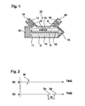
- Fig. 1 shows an embodiment of an ultrasonic flowmeter according to the present invention.
- Fig. 1 is a sectional view of the ultrasonic flowmeter.
- An ultrasonic flowmeter 10 shown in Fig. 1 includes a fluid duct 11, an ultrasonic sensor 15 provided at an end of the fluid duct 11, a reflecting plate 16 provided at the other end of the fluid duct 11, and connecting ducts 17 and 19 connected with the fluid duct 11.
- the path of flow in the fluid duct 11 is divided by a partition 12 into a first flow-path 13 and a second flow-path 14.
- the connecting ducts 17 and 19 are connected with the first flow-path 13 of the fluid duct 11 at portions adjacent to one end and to the other end of the fluid duct 11, respectively.
- the connecting ducts 17 and 19 include therein a first connecting path 18 and a second connecting path 20, respectively, the first and second connecting paths 18 and 20 communicating with the first flow-path 13.
- the ultrasonic flowmeter 10 when a gas G flows into the fluid duct 11 through the first connecting path 18, the first flow-path 13 and the second flow-path 14 of the fluid duct 11 are filled with the gas G, then the gas G flows out through the second connecting path 20. While the gas G is kept flowing into the fluid duct 11 through the first connecting path 18, the gas G is kept flowing from the first connecting path 18 to the second connecting path 20 through the first flow-path 13, and the gas G filling the second flow-path 14 remains in the second flow-path 14 without substantially moving.
- Pulsed ultrasonic waves outputted from the ultrasonic sensor 15 reach the reflecting plate 16 through the first and second flow-paths 13 and 14.
- the ultrasonic wave D passing the second flow-path 14 is reflected by the reflecting plate 16 and reaches the ultrasonic sensor 15 through the first flow-path 13.
- the ultrasonic waves C and D are received by the ultrasonic sensor 15 which has been switched into a receiving mode after having outputted the pulsed ultrasonic waves C and D.
- the gas G flows between the first connecting path 18 and the second connecting path 20 in a direction from the ultrasonic sensor 15 toward the reflecting plate 16. Therefore, the speed of the ultrasonic wave C transmitted in the first flow-path 13 from the ultrasonic sensor 15 to the reflecting plate 16 is higher than the speed of the ultrasonic wave D transmitted from the reflecting plate 16 to the ultrasonic sensor 15. Since the gas G does not flow in the second flow-path 14, the speed of the ultrasonic wave D transmitted from the ultrasonic sensor 15 to the reflecting plate 16 is the same as that of the ultrasonic wave C transmitted from the reflecting plate 16 to the ultrasonic sensor 15.
- the ultrasonic wave C which is outputted by the ultrasonic sensor 15 simultaneously with the ultrasonic wave D and transmitted through the first flow-path 13 from the ultrasonic sensor 15 toward the reflecting plate 16, returns to and is received by the ultrasonic sensor 15 earlier than the ultrasonic wave D transmitted back to the ultrasonic sensor 15 from the reflecting plate 16 through the first flow-path 13.
- the difference between the time of receipt of the ultrasonic wave C and that of the ultrasonic wave D is proportional to the speed of flow of the gas G in the first flow-path 13. Therefore, the speed and the quantity of flow of the gas G can be measured by detecting the difference between the times of receipt of each of the ultrasonic waves C and D.
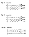
- Fig. 2 shows the relationship in time between a signal of emission and signals of receipt of ultrasonic waves outputted by the ultrasonic sensor 15.
- the signal of emission is shown on a line (a)
- the signals of receipt are shown on a line (b).
- a pulsed signal S t is transmitted in such a manner that the signal S t is outputted by the ultrasonic sensor 15 as a signal of emission of the ultrasonic waves C and D which are transmitted through the first and second flow-paths 13 and 14, respectively, to the reflecting plate 16, and transmitted back to and received by the ultrasonic sensor 15.
- the ultrasonic wave C which reaches the ultrasonic sensor 15 earlier than the other is received thereby as a signal S c .
- the ultrasonic wave D which reaches the ultrasonic sensor 15 later than the ultrasonic wave C, is received by the ultrasonic sensor 15 as a signal S d .
- There is a difference D t in time between the signals S c and S d As described above, the difference in time D t is proportional to the speed of flow of the gas G; therefore, by detecting the difference in time D t , the speed and the quantity of flow of the gas G can be measured.
- the ultrasonic wave D reaches the ultrasonic sensor 15 earlier than the ultrasonic wave C. Therefore, the signal S d is inputted to the ultrasonic sensor 15 earlier than the signal S c . In this case, the speed and the quantity of flow of the gas G can be also measured in the same way.
- the ultrasonic sensor 15 generates pulsed ultrasonic waves in the above-described embodiment, the ultrasonic waves may be generated in a burst mode by the ultrasonic sensor 15, in which a plurality of waves are outputted simultaneously.
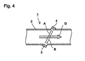
- FIG. 3A, 3B, and 3C shows waveforms, when the ultrasonic sensor 15 generates ultrasonic waves in a burst mode, of a receipt signal S e of an ultrasonic wave E transmitted from the ultrasonic sensor 15 toward the reflecting plate 16 through the first flow-path 13, a receipt signal S f of an ultrasonic wave F transmitted from the reflecting plate 16 toward the ultrasonic sensor 15 through the first flow-path 13, and an output signal Sg which the ultrasonic sensor 15 outputs by receiving the signals S e and S f and combining the same.
- Fig. 3A shows a case in which the speed of flow of the gas G is zero.
- Fig. 3B shows a case in which the gas G flows at a certain speed.
- FIG. 3C shows a case in which the gas G flows at a speed higher than in the case shown in Fig. 3B .
- the horizontal axes denote time and the vertical axes denote the amplitude of the signals.
- the receipt signal S e starts earlier than the receipt signal S f , the receipt signals S e and S f having different phases.
- the amplitude of the output signal Sg including the receipt signals S e and S f being combined is decreased compared with the case in which the gas G does not flow, because some portions of the receipt signals S e and S f cancel each other.
- the speed of flow of the gas G can be detected not only by using the difference in time between the signals of receipt by the ultrasonic sensor 15, but also by using the amplitude of the signals outputted by the ultrasonic sensor 15.
- the quantity of flow can be measured by using one ultrasonic sensor, thereby reducing the manufacturing cost compared with the conventional ultrasonic flowmeter using two ultrasonic sensors.
- the reduction in manufacturing cost of the ultrasonic flowmeter is also possible because it is not necessary to consider the variations in characteristics of ultrasonic sensors since a configuration with one ultrasonic sensor is used.
- the present invention is not limited to the ultrasonic flowmeter for gasses, and it may be also applied to an ultrasonic flowmeter for measuring the quantity of flow of a liquid.
- the ultrasonic flowmeter includes a fluid duct having therein first and second flow-paths separated by a partition and an ultrasonic sensor provided at one end of the fluid duct.
- a reflecting plate provided at the other end of the fluid duct reflects ultrasonic waves generated by the ultrasonic sensor and reaching the reflecting plate through the first and second flow-paths, and returns the ultrasonic waves to the ultrasonic sensor through the second and first flow-paths different from the first and second flow-paths, respectively, through which the ultrasonic waves have reached the reflecting plate.
- First and second connecting paths communicate with the first flow-path at the vicinity of one end and the other end, respectively, of the fluid duct.
Landscapes
- Physics & Mathematics (AREA)
- Electromagnetism (AREA)
- Fluid Mechanics (AREA)
- General Physics & Mathematics (AREA)
- Measuring Volume Flow (AREA)
Claims (2)
- Ein Ultraschallströmungsmesser (10), der folgende Merkmale umfasst:einen Fluidkanal (11), der darin einen ersten und einen zweiten Flussweg (13, 14) umfasst, die durch eine Trennwand (12) getrennt sind;einen Ultraschallsensor (15), der an einem Ende des Fluidkanals (11) vorgesehen ist;eine reflektierende Platte (16), die an dem anderen Ende des Fluidkanals (11) vorgesehen ist, zum Reflektieren von Ultraschallwellen, die durch den Ultraschallsensor (15) erzeugt werden und die reflektierende Platte (16) durch den ersten und zweiten Flussweg (13, 14) erreichen, und zum Zurücksenden der Ultraschallwellen zu dem Ultraschallsensor (15) durch den zweiten beziehungsweise ersten Flussweg (13, 14),die sich von dem ersten beziehungsweise zweiten Flussweg (13, 14) unterscheiden,durch die die Ultraschallwellen die reflektierende Platte (16) erreicht haben; undeinen ersten und einen zweiten Verbindungsflussweg (18, 20), die mit dem ersten Flussweg (13) in der Nähe des einen Endes beziehungsweise des anderen Endes des Fluidkanals (11) kommunizieren;dadurch gekennzeichnet, dassder erste und der zweite Verbindungsflussweg (18, 20) angeordnet sind, um sowohl den ersten Flussweg (13) als auch den zweiten Flussweg (14) des Fluidkanals (11) mit einem Fluid (G) zu füllen; undder erste und der zweite Verbindungsflussweg (18, 20) angeordnet sind, um das Fluid (G) entlang dem ersten Flussweg (13) fließend zu halten, während das Fluid (G),das den zweiten Flussweg (14) füllt, in dem zweiten Flussweg (14) bleibt, ohne sich wesentlich zu bewegen.
- Ein Ultraschallströmungsmesser (10) gemäß Anspruch 1, der ferner einen ersten und einen zweiten Verbindungskanal (17, 19) umfasst, die mit dem Fluidkanal (11) in der Nähe des einen Endes beziehungsweise des anderen Endes des Fluidkanals (11) verbunden sind, wobei der erste und der zweite Verbindungskanal (17,19) den ersten beziehungsweise den zweiten Verbindungsflussweg (18, 20) umfassen.
Applications Claiming Priority (2)
| Application Number | Priority Date | Filing Date | Title |
|---|---|---|---|
| JP19636999 | 1999-07-09 | ||
| JP19636999A JP3341721B2 (ja) | 1999-07-09 | 1999-07-09 | 超音波式流量計 |
Publications (2)
| Publication Number | Publication Date |
|---|---|
| EP1067366A1 EP1067366A1 (de) | 2001-01-10 |
| EP1067366B1 true EP1067366B1 (de) | 2010-08-11 |
Family
ID=16356723
Family Applications (1)
| Application Number | Title | Priority Date | Filing Date |
|---|---|---|---|
| EP00114528A Expired - Lifetime EP1067366B1 (de) | 1999-07-09 | 2000-07-06 | Ultraschall-Durchflussmesser unter Verwendung nur eines Sensors |
Country Status (4)
| Country | Link |
|---|---|
| US (1) | US6520027B1 (de) |
| EP (1) | EP1067366B1 (de) |
| JP (1) | JP3341721B2 (de) |
| DE (1) | DE60044795D1 (de) |
Families Citing this family (8)
| Publication number | Priority date | Publication date | Assignee | Title |
|---|---|---|---|---|
| US6820500B2 (en) * | 2002-07-10 | 2004-11-23 | Honeywell International Inc. | Small pipe bore ultrasonic flowmeter detector |
| DE102005001897C5 (de) * | 2005-01-14 | 2013-01-17 | Landis+Gyr Gmbh | Ultraschallmessanordnung für den Einbau an einem Einrohranschlussstück in einer Rohrleitung |
| DE102005001895B4 (de) * | 2005-01-14 | 2007-09-06 | Landis+Gyr Gmbh | Vorrichtung zur Durchflussmessung |
| DE102005062628B3 (de) * | 2005-12-23 | 2007-05-31 | Hydrometer Gmbh | Ultraschallzähler |
| JP4931550B2 (ja) * | 2006-10-27 | 2012-05-16 | リコーエレメックス株式会社 | 超音波流量計 |
| CN102023038B (zh) * | 2009-09-22 | 2012-02-22 | 贵州航天凯山石油仪器有限公司 | 一种管道流量的超声波测量方法 |
| KR101059928B1 (ko) | 2009-11-30 | 2011-08-29 | 주식회사 에스앤씨 | 유량측정장치의 유량측정관체 |
| DE102011000269A1 (de) * | 2011-01-21 | 2012-07-26 | Zenner International Gmbh & Co. Kg | Vorrichtung zur Durchflußmessung |
Family Cites Families (2)
| Publication number | Priority date | Publication date | Assignee | Title |
|---|---|---|---|---|
| JP2556701B2 (ja) * | 1987-05-18 | 1996-11-20 | グラム株式会社 | 限外濾過量及び透析液濃度測定装置 |
| DE19649437C1 (de) * | 1996-11-28 | 1998-05-20 | Siemens Ag | Verfahren und Anordnung zur Messung der Fließgeschwindigkeit eines Mediums |
-
1999
- 1999-07-09 JP JP19636999A patent/JP3341721B2/ja not_active Expired - Fee Related
-
2000
- 2000-07-06 EP EP00114528A patent/EP1067366B1/de not_active Expired - Lifetime
- 2000-07-06 DE DE60044795T patent/DE60044795D1/de not_active Expired - Lifetime
- 2000-07-10 US US09/612,843 patent/US6520027B1/en not_active Expired - Fee Related
Also Published As
| Publication number | Publication date |
|---|---|
| EP1067366A1 (de) | 2001-01-10 |
| JP2001021398A (ja) | 2001-01-26 |
| JP3341721B2 (ja) | 2002-11-05 |
| US6520027B1 (en) | 2003-02-18 |
| DE60044795D1 (de) | 2010-09-23 |
Similar Documents
| Publication | Publication Date | Title |
|---|---|---|
| US6089104A (en) | Ultrasonic flow meter using transit time across tube chords for determining the flow rates | |
| US7437948B2 (en) | Ultrasonic flowmeter and ultrasonic flow rate measurement method | |
| US20040176917A1 (en) | Ultrasonic flow-measuring method | |
| US5717145A (en) | Detector for an ultrasonic flow meter | |
| US10184816B2 (en) | Measurement unit and flow rate meter | |
| CN107076602B (zh) | 用于外夹式超声波流量测量的方法和布置系统以及用于控制外夹式超声波流量测量的电路布置系统 | |
| EP1067366B1 (de) | Ultraschall-Durchflussmesser unter Verwendung nur eines Sensors | |
| CN100401022C (zh) | 超声波流量计和超声波流量测量方法 | |
| US6584862B1 (en) | Ultrasonic flowmeter for flowing media | |
| US20060278015A1 (en) | Device for determination and/or monitoring of the volumetric and/or mass flow of a medium | |
| US6536290B2 (en) | Ultrasonic flowmeter and gas flowmeter using the same | |
| EP0712486B1 (de) | Verbesserungen bezüglich der überwachung von flüssigkeitsströmungen | |
| EP3254065B1 (de) | Flüssigkeitsströmungseigenschaften in einem kanalisierungsprozessmassenstrom durch induzierung einer stehenden welle darin | |
| US4446744A (en) | Ultrasonic flowmeter | |
| NL8901044A (nl) | Stromingsmeter. | |
| CA2557099A1 (en) | Doppler type ultrasonic flow meter | |
| JPS6261893B2 (de) | ||
| JP3653829B2 (ja) | 流速計 | |
| JP3383576B2 (ja) | 流量計の脈動吸収構造 | |
| JPH0915012A (ja) | 超音波流量計 | |
| JP3005272B2 (ja) | フルイディック流量計 | |
| JP4178899B2 (ja) | 流量計 | |
| JP2001059756A (ja) | 計測装置 | |
| JPS60327A (ja) | 渦流量計 | |
| JPS59187222A (ja) | 渦流量計 |
Legal Events
| Date | Code | Title | Description |
|---|---|---|---|
| PUAI | Public reference made under article 153(3) epc to a published international application that has entered the european phase |
Free format text: ORIGINAL CODE: 0009012 |
|
| 17P | Request for examination filed |
Effective date: 20000706 |
|
| AK | Designated contracting states |
Kind code of ref document: A1 Designated state(s): DE FR GB |
|
| AX | Request for extension of the european patent |
Free format text: AL;LT;LV;MK;RO;SI |
|
| AKX | Designation fees paid |
Free format text: DE FR GB |
|
| 17Q | First examination report despatched |
Effective date: 20060721 |
|
| RAP1 | Party data changed (applicant data changed or rights of an application transferred) |
Owner name: MURATA MANUFACTURING CO., LTD. |
|
| GRAP | Despatch of communication of intention to grant a patent |
Free format text: ORIGINAL CODE: EPIDOSNIGR1 |
|
| GRAS | Grant fee paid |
Free format text: ORIGINAL CODE: EPIDOSNIGR3 |
|
| GRAA | (expected) grant |
Free format text: ORIGINAL CODE: 0009210 |
|
| AK | Designated contracting states |
Kind code of ref document: B1 Designated state(s): DE FR GB |
|
| REG | Reference to a national code |
Ref country code: GB Ref legal event code: FG4D |
|
| REF | Corresponds to: |
Ref document number: 60044795 Country of ref document: DE Date of ref document: 20100923 Kind code of ref document: P |
|
| PLBE | No opposition filed within time limit |
Free format text: ORIGINAL CODE: 0009261 |
|
| STAA | Information on the status of an ep patent application or granted ep patent |
Free format text: STATUS: NO OPPOSITION FILED WITHIN TIME LIMIT |
|
| 26N | No opposition filed |
Effective date: 20110512 |
|
| REG | Reference to a national code |
Ref country code: DE Ref legal event code: R097 Ref document number: 60044795 Country of ref document: DE Effective date: 20110512 |
|
| GBPC | Gb: european patent ceased through non-payment of renewal fee |
Effective date: 20110706 |
|
| REG | Reference to a national code |
Ref country code: FR Ref legal event code: ST Effective date: 20120330 |
|
| PG25 | Lapsed in a contracting state [announced via postgrant information from national office to epo] |
Ref country code: FR Free format text: LAPSE BECAUSE OF NON-PAYMENT OF DUE FEES Effective date: 20110801 Ref country code: DE Free format text: LAPSE BECAUSE OF NON-PAYMENT OF DUE FEES Effective date: 20120201 |
|
| REG | Reference to a national code |
Ref country code: DE Ref legal event code: R119 Ref document number: 60044795 Country of ref document: DE Effective date: 20120201 |
|
| PG25 | Lapsed in a contracting state [announced via postgrant information from national office to epo] |
Ref country code: GB Free format text: LAPSE BECAUSE OF NON-PAYMENT OF DUE FEES Effective date: 20110706 |