EP1066689B1 - Reception method and receiver - Google Patents
Reception method and receiver Download PDFInfo
- Publication number
- EP1066689B1 EP1066689B1 EP99964719A EP99964719A EP1066689B1 EP 1066689 B1 EP1066689 B1 EP 1066689B1 EP 99964719 A EP99964719 A EP 99964719A EP 99964719 A EP99964719 A EP 99964719A EP 1066689 B1 EP1066689 B1 EP 1066689B1
- Authority
- EP
- European Patent Office
- Prior art keywords
- delay values
- receiver
- optimal
- propagation delay
- states
- Prior art date
- Legal status (The legal status is an assumption and is not a legal conclusion. Google has not performed a legal analysis and makes no representation as to the accuracy of the status listed.)
- Expired - Lifetime
Links
Images


Classifications
-
- H—ELECTRICITY
- H04—ELECTRIC COMMUNICATION TECHNIQUE
- H04B—TRANSMISSION
- H04B7/00—Radio transmission systems, i.e. using radiation field
- H04B7/02—Diversity systems; Multi-antenna system, i.e. transmission or reception using multiple antennas
- H04B7/04—Diversity systems; Multi-antenna system, i.e. transmission or reception using multiple antennas using two or more spaced independent antennas
- H04B7/08—Diversity systems; Multi-antenna system, i.e. transmission or reception using multiple antennas using two or more spaced independent antennas at the receiving station
- H04B7/0868—Hybrid systems, i.e. switching and combining
- H04B7/0874—Hybrid systems, i.e. switching and combining using subgroups of receive antennas
-
- H—ELECTRICITY
- H04—ELECTRIC COMMUNICATION TECHNIQUE
- H04B—TRANSMISSION
- H04B1/00—Details of transmission systems, not covered by a single one of groups H04B3/00 - H04B13/00; Details of transmission systems not characterised by the medium used for transmission
- H04B1/69—Spread spectrum techniques
- H04B1/707—Spread spectrum techniques using direct sequence modulation
- H04B1/7097—Interference-related aspects
- H04B1/711—Interference-related aspects the interference being multi-path interference
- H04B1/7113—Determination of path profile
-
- H—ELECTRICITY
- H04—ELECTRIC COMMUNICATION TECHNIQUE
- H04B—TRANSMISSION
- H04B7/00—Radio transmission systems, i.e. using radiation field
- H04B7/02—Diversity systems; Multi-antenna system, i.e. transmission or reception using multiple antennas
- H04B7/04—Diversity systems; Multi-antenna system, i.e. transmission or reception using multiple antennas using two or more spaced independent antennas
- H04B7/08—Diversity systems; Multi-antenna system, i.e. transmission or reception using multiple antennas using two or more spaced independent antennas at the receiving station
- H04B7/0891—Space-time diversity
-
- H—ELECTRICITY
- H04—ELECTRIC COMMUNICATION TECHNIQUE
- H04B—TRANSMISSION
- H04B1/00—Details of transmission systems, not covered by a single one of groups H04B3/00 - H04B13/00; Details of transmission systems not characterised by the medium used for transmission
- H04B1/69—Spread spectrum techniques
- H04B1/707—Spread spectrum techniques using direct sequence modulation
- H04B1/7097—Interference-related aspects
- H04B1/711—Interference-related aspects the interference being multi-path interference
- H04B1/7115—Constructive combining of multi-path signals, i.e. RAKE receivers
- H04B1/7117—Selection, re-selection, allocation or re-allocation of paths to fingers, e.g. timing offset control of allocated fingers
-
- H—ELECTRICITY
- H04—ELECTRIC COMMUNICATION TECHNIQUE
- H04B—TRANSMISSION
- H04B7/00—Radio transmission systems, i.e. using radiation field
- H04B7/02—Diversity systems; Multi-antenna system, i.e. transmission or reception using multiple antennas
- H04B7/04—Diversity systems; Multi-antenna system, i.e. transmission or reception using multiple antennas using two or more spaced independent antennas
- H04B7/08—Diversity systems; Multi-antenna system, i.e. transmission or reception using multiple antennas using two or more spaced independent antennas at the receiving station
- H04B7/0837—Diversity systems; Multi-antenna system, i.e. transmission or reception using multiple antennas using two or more spaced independent antennas at the receiving station using pre-detection combining
- H04B7/0842—Weighted combining
- H04B7/0848—Joint weighting
- H04B7/0857—Joint weighting using maximum ratio combining techniques, e.g. signal-to- interference ratio [SIR], received signal strenght indication [RSS]
Definitions
- the invention relates to a reception method wherein signals supplied from a radio path are received, and each signal which arrives at a receiver is delayed by a unique delay value.
- a signal travelling between a user and a base station does not travel straight but, depending on characteristics of the environment, propagates along a plurality of paths of different lengths from a transmitter to a receiver.
- Multipath propagation is mainly caused by the fact that a radio signal is reflected and scatters from obstacles on the propagation path of the signal. If signals travelling along different paths have a propagation delay of different length, it is possible for the signals to arrive at a receiver with different phases.
- a radio system can use a so-called RAKE receiver, which comprises one or more RAKE fingers.
- Each finger is an independent receiver which serves to compose and demodulate received signal components.
- the value of the propagation delay of a signal received by a finger can be selected such that the value corresponds to a delay caused to the radio signal by a certain propagation path.
- the signal components of different receiver fingers are combined, whereby a high-quality signal can be generated.
- Radio systems use the CDMA method, for example, wherein a narrowband data signal is modulated by a spreading code which is more broadband than the data signal, whereby the data signal is spread over a relatively broad band.
- the spreading code usually comprises a long pseudorandom bit sequence.
- Each user of a subscriber terminal has a unique spreading code during a connection.
- a plurality of users can simultaneously transmit a signal over the same frequency band.
- the signals to be transmitted are separated from each other at the receiver on the basis of the pseudorandom spreading code.
- the propagation delay of the signal can be indicated as a delay of the spreading code wave form, for example.
- A- RAKE receiver can be applied to base stations and subscriber terminals.
- the subscriber terminals can be mobile telephones, for example.
- the RAKE receiver can be used, for example, in such a manner that it combines signals supplied from different base stations and different antenna sectors. This means that the RAKE receiver is suitable for use in soft handover and in softer handover when a transition is carried out from an antenna sector of a base station to another.
- the correlators of the RAKE fingers should be optimally adjusted.
- a correlator of the RAKE finger is optimally adjusted when the delay of the spreading code wave form formed by the correlator corresponds as closely as possible to the propagation delay of the signal propagated on the radio path.
- the propagation delay of the signal can be determined from impulse response formed from the signal received from the radio channel.
- the channel impulse response reveals the distribution of the total received signal power among different propagation delays.
- Different delay components can be calculated from the correlation between the received signal and the spreading code wave form, the correlation being determined for delays of the spreading code wave form of different lengths.
- the correlations can be determined for the spreading code by means of a matched filter. The matched filter enables even a large number of delay values to be determined efficiently.
- RAKE finger allocation A procedure of adjusting the delays of the spreading codes of the correlators of RAKE fingers to correspond to estimated values of the propagation delay of a radio wave is called RAKE finger allocation.
- RAKE fingers are allocated by setting the delays of the spreading code wave forms of the correlators to correspond to maximum power points occurring in measured impulse response
- EP 0 877 493 presents synchronisation in a multipath spread spectrum communication receiver with a synchronizer circuit.
- the synchronizer circuit comprises a tracking section performing control to separate a plurality of demodulation paths made of signals received by space diversity antennas. If, for example, the chip phase difference between the first tracking path having the largest correlation component and the second tracking path, whose chip phase is nearest to that of the first tracking path, is less than one chip, the tracking section separates the chip phase of the second tracking path from that of the first tracking path by one chip.
- the code phases of the RAKE fingers are selected to correspond to the power maximums of the impulse response.
- the prior art solutions also use so-called code tracking to adjust the delay of the RAKE finger in an attempt to set the code phase more accurately at the maximum in the power density of the channel. Selecting the maximums and code tracking cause problems if the impulse response of the channel does not comprise maximum points clearly located separately. If code tracking moves the RAKE fingers near each other, the performance deteriorates since the fingers receive signal components propagated along the same multipaths. In such a case, the proportion of some multipaths in a maximal-ratio-combined signal becomes overemphasized and the quality of the combined signal deteriorates. The selection of the maximums may also cause part of the signal associated with the wide power maximum to be lost.
- An object of the invention is thus to provide a reception method and a receiver so as to enable the above-mentioned problems to be solved. This is achieved by the reception method of independent claim 1 and the receiver of independent claim 16.
- the invention is based on the idea that optimal delays (spreading code phases) are found for the fingers of a RAKE receiver by estimating the impulse response of the channel, which is formed from the power densify of the signal at feasible values of propagation delays. Furthermore the invention is based on the idea that the optimal delay values are found on the basis of the impulse response of a measured channel by using a specific optimization algorithm. Using the optimization algorithm guarantees that the code phases selected for the RAKE fingers sufficiently deviate from each other, i.e. the fingers are at least a so-called minimum distance away from each other.
- the selection of suitable code phases is based on the fact that the selected code phases meet certain optimality conditions characteristic of the invention.
- the conditions are set so as to enable a signal of as high quality as possible to be achieved, the signal being formed by combining signals supplied from different RAKE fingers.
- a trellis diagram i.e. a network diagram, is utilised in finding the code phases which meet the optimality conditions.
- An optimal route determined through the trellis diagram is utilised in searching for the code phases.
- the weight values of the transitions in the trellis diagram are selected by utilising the impulse response measured for the radio channel.
- the method and receiver of the invention provide several advantages over the known methods and receiver solutions.
- the problems with the selection of the maximums and code tracking are avoided by the method of the invention since the delays are selected such that the receiver catches the most part of the signal regardless of the details of the impulse response form.
- the reception method can be used although the impulse response of the channel comprises only one power maximum.
- the power maximum of the impulse response comprises several multipath-propagated signal components located near each other, the existence of the signal components being indicated by the broadening of the power maximum.
- the power maximum is optimally distributed among several fingers if the width of the maximum is sufficient.
- the reception achieves sensitivity greater than that in the known solutions.
- the reception of a wide impulse response peak can easily be distributed among several fingers since the minimum distance condition characteristic of the invention used in the selection of the delays of the fingers guarantees that different fingers receive signal components propagating along separate multipaths.
- the method of the invention enables optimal finger positions to be found. Furthermore, the optimal number of fingers of the receiver can be determined by the method.
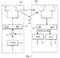
- Figure 1 shows a schematic view of a radio system comprising a transmitter 100 and a receiver 200.
- the radio system uses a reception method of the invention.
- the transmitter in the radio system in accordance with Figure 1 is, for example, a base station or a subscriber terminal.
- the subscriber terminal can be, for example, a mobile telephone.
- the receiver shown in the figure is, for example, a base station or a subscriber terminal.
- the radio system shown can be based, for example, on CDMA technique.
- the reception method of the invention wherein estimation is performed of the propagation delay of a radio signal to be transmitted between the transmitter and the receiver is not, however, restricted to be only used in the CDMA radio systems but the method is also suitable for use in TDMA-based radio systems, such as GSM systems, for example.
- the figure shows that between the transmitter 100 and the receiver 200 there is an obstacle 19 in the way of the signal to be transmitted, causing the signal to be reflected. Part of the signal to be transmitted does, however, propagate to the receiver in a relatively direct manner. Reflections, for example, cause the signal components to arrive at the receiver 200 nonsimultane-ously. A so-called multipath channel is created between the transmitter and the receiver in the radio system according to the figure.
- the transmitter 100 comprises a signal spreader 14, a summing device 13, a device 12 and transmission antennas 11.
- the receiver 200 comprises reception antennas 17, a device 16 and a number of RAKE receivers 15.
- the signal spreader 14 receives a narrowband signal comprising bits which are spread into a broadband signal at the spreader.
- the bits received by the spreader 14 are channel-coded.
- the signal is spread by, for example, multiplying the bits to be transmitted by a spreading code, which results in a broadband signal.
- the output signal of the spreader 14 is supplied to the summing device 13, which adds the signal supplied from the spreader 14 to the output signals of other spreaders possibly located at the same transmitter. From the summing device 13, the broadband sum signal is supplied to the device 12, which converts the received digital signal into an analogue baseband signal. Additionally, the device 12 converts the baseband signal further into an RF signal, which is transmitted to the radio path by the transmission antennas.
- the reception antennas 17 at the receiver 200 receive the RF signals transmitted by the transmitter 100.
- the received signals are supplied to the device 16, which converts the RF signals received from the antennas into analogue baseband signals.
- the baseband signals are converted into a digital form at the device 16.
- the signals received from the device 16 are supplied to one or more RAKE receivers 15.
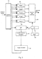
- FIG. 2 shows the structure of the receiver 200 of the invention.
- the receiver of the invention is preferably a RAKE receiver comprising a selector 10, a number of RAKE fingers 20 and a combiner 60.
- the selector selects signals to be supplied to each RAKE finger.
- the fingers decode the spreading code added to the signal at the transmitter.
- the receiver of the invention can be located at a subscriber terminal or a base station, for example. Although the structure of the receiver is described from the point of view of a RAKE receiver, the receiver is not entirely restricted to the RAKE receiver but the receiver can be of a different type as well.
- the receiver further comprises a device 30 connected to the selector 10.
- the device 30 receives a signal from the selector.
- the device 30 is, in practice, a filter arranged in the spreading code used for measuring the impulse response of the channel.
- the receiver further comprises a device 40 and a finger distributor 50.
- the device 40 receives a signal from the device 30.
- the device 40 generates impulse responses for the received signals, which impulse responses enable the propagation delay profile of the channel to be determined, the propagation delay profile comprising the estimated power density of the impulse response of the channel.
- the power density is estimated by different values of the propagation delay.
- the device 40 can, for example, average out the impulse response values.
- Information about the propagation delay profile is supplied to the distribution device 50, which selects the spreading code phases for the fingers.
- the distribution device 50 thus determines the spreading code phases by using the signal strengths measured for different delays by the devices 30, 40, the signal strengths forming the impulse response of the channel.
- the device 30 and the distribution device 50 determine the strength of a part of a signal delayed by a specific propagation delay by several values of the propagation delay.
- the distribution device 50 compares the delay differences of the received signals with each other.
- the distribution device 50 can be implemented by a microcircuit based on ASIC technology, for example.
- the functions of the distribution device 50 can at least partly be implemented by software.
- the receiver further comprises a device 70 and a device 80.
- the device 70 controls the operation of the different parts of the receiver.
- the device 70 is a microprocessor, for example.
- Information necessary for the different functions of the receiver can be stored at the device 80.
- the device 80 is, in practice, a memory circuit wherefrom the device 70 retrieves information and wherein the device 70 can store information when necessary.
- FIG 3 shows in closer detail a RAKE finger wherein correlation for the signal is carried out and the spreading code is decoded.
- the RAKE finger comprises a spreading code generator 21, a device 22, a multiplication device 23 and a summing device 24.
- the receiver further comprises a device 25, which, on the basis of the code phase information received from the distribution device 50, either delays or advances the spreading code bit sequence generated by the spreading code generator 21.
- the spreading code generator 21 can generate a pseudo-random bit sequence similar to the spreading code used at the spreader 14 of the transmitter.
- the code phases of the RAKE fingers can be selected by utilising the propagation delay profile of the channel, in the determination of which the matched filter of the spreading code can be used.
- the delay profile can also be determined in some other way than by the device 30.
- the device 30 is a matched filter.
- the delays of the spreading codes are adjusted at the receiver such that they correspond to the estimated propagation delays of the radio wave as accurately as possible. Selecting and adjusting the delays of the spreading codes are also called RAKE finger allocation.
- a search is conducted for a propagation delay value which corresponds to a certain phase of the spreading code generator 21 by the distribution device 50.
- a signal 28 is generated on the basis of the delay value found by the distribution device 50, and the receiver advances or delays the spreading code bit sequence by this signal.
- the device 22 selects a correct sampling point on the basis of the information contained in the signal 28.
- the device 22 receives a spreading-coded signal 26 received by the antenna.
- the device 22 can lower the sampling rate of the signal, whereby one sample can correspond to one chip, for example, i.e. a bit of a spreading code. In lowering the sampling rate, the device 22 can use decimation or interpolation, for example.
- the signal generated by the device 22 and the signal generated by the spreading code generator 21 are supplied to the multiplication device 23, at which the signals are multiplied by each other. Multiplying the signals removes the spreading code from the signal.
- the multiplication device 23 provides multiplication results which are summed at the summing device 24. Summing the multiplication results is carried out such that samples are added up from which the spreading code is decoded and which are associated with the same bit.
- the bits provided from the output of the summing device 24 are supplied to the combiner 60.
- the delays of the RAKE fingers i.e. the phases of the spreading code generators of the fingers, must not locate too close to each other. If the differences between the code phases are too small, the RAKE fingers receive partly the same multipath components, which are thus overemphasized at reception.
- the weighting of the kind mentioned above may lead to deterioration in the quality of the maximal-ratio-combined signal.
- the receiver can use the following minimum distance condition: t a - t b ⁇ d_min .
- Terms t a and t b in the minimum distance condition designate the relative delays (phase differences) of RAKE fingers a and b demodulating the same antenna signal.
- the delay value set for the RAKE finger and the phase of the spreading code generator corresponding to the delay value are called a RAKE finger allocation point.
- the above-mentioned condition means that different allocation points must have a difference of a magnitude of at least d_min.
- the propagation delay profile of the channel is estimated by determining the power density of the signal for possible values of the propagation delays.
- Each value of the propagation delay is restricted to a certain range of finite size due to, for example, the finite magnitude of the physical distance between the transmitter and the receives.
- the variation range of the propagation delay can be covered, for example, such that the power density of the signal to be received is estimated for different delays at intervals of (1/4)Tc, whereby the power densities measured for different propagation delays constitute the impulse response estimate of the channel.
- the RAKE finger allocation points are selected in such a manner, for example, that the sum of the impulse response samples corresponding to the allocation points is maximized.
- the allocation points are required to meet the minimum distance condition.
- FIG. 4 shows a possible trellis diagram.
- the network of Figure 4 comprises layers and transitions between the layers. The number of the layers is the same as the number of the impulse response estimates. Each layer of the network comprises a number of states, i.e. nodes.
- the trellis diagram according to Figure 4 relates to a case wherein delay values are selected for one, two or three RAKE fingers when the required minimum distance of the allocation points is at least three sample intervals of the impulse response estimation. The method can, however, be easily modified to suit cases wherein the number of the RAKE fingers or the minimum distance of allocation points obtains another value.
- Each sample S(i) of the impulse response estimate corresponds to one layer of the network.
- a weight value dependent on the impulse response estimate is attached to the transitions between the layers.
- a path travelling through the network i.e. a route, is optimal if the sum of the weight values of the transitions of the path is higher than the sum of the weight values of the transitions of all other possible paths terminating at the same state of the network.
- Figure 5 shows a diagram wherein the transitions between different layers are provided with a weight value, whereby the optimality of the paths can be compared with each other. If the impulse response estimate comprises L samples: S(0), S(1), ..., S(L-1), optimal RAKE finger allocation points can be found on paths terminating at layer L-1 of the network.
- Figure 6 shows a trellis diagram such that the first and the last layers of the diagram are included in the figure.
- the states at node point A of the diagram are so-called 'zero states'.
- Each allowed path that travels through the network starts from a zero state of the diagram.
- State E is the first zero state from which a path travelling through the network can in principle start. If only one allocation point is to be found for the RAKE receiver, the delay value can be found by following the optimal path which ends at node point B. If two allocation points are to be found, the delay values can be found by following the optimal path which ends at node point C. If three allocation points are to be found, the delay values can be found by following the path terminating at state D. In all cases, the weight of the optimal path is a sum of power density samples S(j) corresponding to allocation points j.
- the problem concerning finger allocation is solved in such a manner that the length of the impulse response is increased gradually.
- a search is conducted for optimal positions for all numbers of the fingers that are smaller than a certain maximum number. This is carried out by increasing the examined propagation delay range little by little. In each step. the propagation delay range is increased by one sample value, for example. An optimum is searched for by utilising the optimum points found earlier for a smaller propagation delay range and for different numbers of the fingers.
- the search for values of the propagation delays is conducted in two steps.
- the intermediate steps of the search procedure resemble a so-called Viterbi algorithm used in decoding convolution codes, which is an application of a mathematical calculation technique called dynamic programming.
- optimal routes are established through the trellis diagram shown in Figures 4, 5 and 6 .
- the optimal path terminating at layer L-1 of the network is followed back through the network, whereby the allocation points along the path are found.
- the search for an optimal route proceeds layer by layer as shown in Figures 7 and 8 .
- Exemplary optimal routes terminating at layer i-1 i.e. so-called survivor paths, are indicated in unbroken lines in Figure 7 .
- Optimal routes terminating at layer i can be established by continuing the paths terminating at layer i-1 such that transition weights corresponding to the transition between layers i-1 and i are added to the weight value of each path, the transition weights being determined, in accordance with Figure 5 , by means of the impulse response estimates S(i). If a transition from layer i-1 to state i of the layer is possible via more than one route, a route with the highest weight value is selected as the optimal route leading to state i.
- the selection decisions are stored in the memory, whereby they are available in the second step of the determination procedure of the RAKE finger allocation points.
- the selection of an optimal route from among two or more paths arriving at a state of the type described above in connection with the Viterbi algorithm is called an ACS (Add, Compare and Select) operation.
- the second step of the procedure is explained by means of Figure 6 .
- the optimal path terminating at the last layer L-1 of the diagram is followed back through the network.
- the allocation points j of the RAKE fingers are thus found on the basis of the information stored in the first step of the procedure.
- the power density samples S(j) corresponding to the allocation points j were added to the weight of the optimal path in the first step of the procedure.
- the delay values determined in this manner are optimal in that the sum of the power density samples S(j) of the impulse responses corresponding to the found allocation points j is the highest possible one which can be obtained when the allocation points of the RAKE fingers are at least the minimum distance apart.
- the value of the minimum distance is three sample intervals of the impulse response.
- Figure 9 illustrates in closer detail the role of the states of the network of the kind shown in Figures 5 to 8 in determining the delay values of the RAKE fingers when the number of the allocation points to be found is N at most.
- sum P(i,f) where f depicts the number of the impulse response samples included in the sum, has been attached to each state of the network power, the power sum P(i,f) corresponding to a state. Said number of impulse response samples is the same as the number of allocation points on the path terminating at the state.
- each layer of the network comprises a separate state for each possible so-called allocation pattern.
- the allocation pattern of the state indicates allocation decisions to be made immediately during the next transitions on the path travelling through the state. If the minimum distance is three sample intervals, the allocation pattern associated with each state of layer i indicates whether a delay value corresponding to impulse response sample S(i+1) or S(i+2) is added to become an allocation point on the path travelling through the state.
- Each transition between two states is associated with an allocation pattern of both the initial state and the final state of the transition. Together these allocation patterns indicate whether one of the three sequential delay values is selected as an allocation point located on the path travelling through the transition.
- the minimum distance condition can now be ensured by determining the allowed states and transitions of the network such that at most one out of the three sequential delay values is allocated to one path travelling through the trellis diagram.
- Figure 9 illustrates one such selection of states and transitions of a network.
- the minimum distance requirement of the RAKE finger allocation points can thus be guaranteed by selecting the structure of the network as shown by way of example in Figures 4 to 9 .
- column A indicates the allocation decisions concerning delay value i corresponding to impulse response sample S(i) that are to be made on the paths travelling through the states belonging to layer i-1.
- Column B in Figure 9 describes the allocation decisions concerning delay value i+1.
- column C in layer i of the network depicts the allocation decisions associated with delay value i+1.
- Column E depicts the decisions associated with point i+2.
- the initial state of the transition in column B must comprise the same value as the final state of the transition in column C since these points correspond to an allocation decision to be made for the same delay i+1.
- at most one out of the three columns A, B or E can comprise the delay value on the basis of which the allocation point is selected.
- a potential allocation point is denoted by the letter F in the figure.
- trellis diagrams corresponding to Figures 4 to 9 can be formed for any number N of the delay values to be found and the minimum distance d_min of allocation points. After the diagrams have been formed, a search for an optimal route can be conducted to determine the delay values j with which the highest sum of corresponding impulse response estimates S(j) can be obtained when the selected delay values j must differ from each other at least a minimum distance d_min. Similarly, it is obvious that the method based on dynamic programming for finding the optimal route by utilising the,trellis diagram is suited for use in a network of any form that comprises sequential layers.
- An optimization criterion used in the method disclosed above is that the sum of the impulse response estimates calculated for the finger allocation points is the highest one that can be obtained without violating the minimum distance condition set for the allocation points. This optimization criterion is not, however, the only feasible one; other kinds of optimization criteria can provide a similar result.
- the first term is the sum used above of the power density estimates corresponding to the finger allocation points.
- the second term can describe interaction of some kind between the allocation points.
- the interaction term can be, for example, such that it prevents the allocation points from becoming too closely located.
- the interaction term can be selected, for example, such that it can be used for subtracting from the sum of the power density estimates the portion of the signal power that becomes received several times by RAKE fingers located near each other.
- the threshold can be steplessly adjusted on the basis of which several RAKE fingers are positioned in a wide power maximum of the impulse response.
- the interaction can generally depend both on allocation points located nearer each other than a certain limit D and the values of the impulse response estimates.
- Figure 10 shows a layer of a generalised trellis diagram.
- the layer relates to a situation wherein, in principle, all possible selections of allocation points are allowed without a minimum distance limit.
- the weights of the transitions between the layers can, however, be dependent on the allocation decisions concerning D sequential delay points. This means that an allocation pattern comprising an allocation decision at D-1 sequential allocation points is attached to the states. Hence, allocation decisions can be made at D sequential delay points on the allocation patterns of the initial state and the final state of a transition between the layers. Information about these allocation decisions can be used in calculating the weight values of the transitions between the states.
- the number of the states which form a terminating point for paths with one selected allocation point is, in a general case, at most 2 (D-1) (state group B). This is due to the fact that each of the D-1 points of the allocation point can be empty or comprise a placing of an allocation point onto the path (symbol F). Similarly, the number of the states which form a terminating point for paths with a greater number of made allocation decisions is at most 2 (D-1) (state group C).
- the number of the zero states of a layer (state group A) is at most 2 (D-2) since the first allocation point is selected in connection with each transition starting from a zero state. Consequently, in Figure 10 in the square on the left side of the allocation patterns of state group A, the letter F has been plotted to denote an allocation selection. The contents of the other D-2 points of the allocation pattern are not fixed, in which case there are at most 2 (D-2) potential allocation patterns of the zero states.
- each layer of the network comprises only one such state the paths leading to which comprise N allocation points. This is due to the fact that in this case there is only one allowed allocation pattern since no new allocation decisions are made on the path leaving the state. Consequently, in the above-mentioned case, the only allowed allocation pattern corresponds to a sequence of empty squares as shown at the lower edge of Figure 10 .
- Figure 11 illustrates the structure of the transitions between two sequential layers of a trellis diagram.
- the trellis diagrams shown in Figure 11 are similar to those shown in Figure 10 .
- the allocation patterns associated with the states are shown in Figure 11 in such a manner that symbol C denotes a part of an allocation pattern comprising D-2 sequential allocation decisions.
- symbol C comprises allocation decisions associated with delay values i+1, i+2, ..., i+D-2.
- the allocation patterns are presented by adding, before or after symbol C of the allocation pattern, either an F to denote the allocation point or a zero to indicate that allocation is not carried out for the delay value in question.
- the F or the zero located before symbol C corresponds to delay value i
- the F or the zero located after symbol C corresponds to delay Value i+D-1.
- the allocation patterns of the states located on the right side in Figure 11 are thus presented by symbols [C, 0] and [C, F].
- P i ⁇ f C ⁇ 0 max ⁇ P ⁇ i - 1 , f - 1 , F ⁇ C + w i F ⁇ C ⁇ 0 , P ⁇ i - 1 , f , 0 ⁇ C + w i 0 ⁇ C ⁇ 0
- P i ⁇ f C ⁇ F max ⁇ P ⁇ i - 1 , f - 1 , F ⁇ C + w i F ⁇ C ⁇ F , P ⁇ i - 1 , f , 0 ⁇ C + w i 0 ⁇ C ⁇ F
- symbol P(i,f,[...]) refers to the sum of the transition weights of an optimal path arriving at a state
- f means the number of the allocations located on the optimal path arriving at the state
- symbols [C, 0], [C, F], [0, C] and [F, C] refer to the allocation patterns of the states, as stated above.
- Symbol w(i,[...]) means that for calculating the transition weight, it is possible to use both information about layer index i and information about the allocation decisions associated with D sequential points i, .. , i+D-1 presented by symbols [F,C,0], [0,C,0], [F,C,F] and [0,C,F] in the formulas and Figure 11 .
- transition weights w(i,[0,C,0]) and w(i,[0,C,F]) corresponding to symbols [0,C,0] and [0,C,F] obtain a value zero since the point corresponding to delay i designated by these symbols is not selected as the allocation point.
- the receiver thus forms sums of the strengths of the signal parts determined by values of a different propagation delay.
- the distribution device 50 located at the receiver selects from among the received signals those signals whose delay values deviate by at least a predetermined delay difference and whose sum of the strengths of the signal parts obtains the highest possible value.
- the receiver indicates the received information by using the signals selected above. In the selection of the delay values, the receiver utilises a trellis diagram with the states and transitions therein being weighted. The weight coefficients used in weighting depend on the strengths of the signals received at different propagation delays.
- the distribution device 50 determines the number of the delay values and the delay values such that the distribution device 50 first determines propagation delays for each number of the propagation delay values.
- the receiver selects the delay values from a route with the highest sum of weight values.
- the distribution device 50 selects the delay values corresponding to one number of the propagation delay values in order to indicate the information.
- the information can be indicated by using prior art methods.
- the distribution device selects the number whereby the increase of the weight coefficient sum ends although the number of the delay values increases.
- the distribution device determines the delay values to be used in indicating the information from a route which corresponds to the optimal number of the delay values.
- the receiver determines the impulse response of the channel in such a manner, for example, that the receiver calculates the correlation between the known bit pattern or chip pattern and the signal received by the receiver. Calculating the correlation is carried out by different delays.
- the chip pattern is determined on the basis of a spreading code.
- a training sequence is utilised in measuring the channel.
- the reception method of the invention can be used in the TDMA system in such a manner, for example, that delay values are selected from the power distribution of the impulse response by the method.
- a mean value of a longer period for example, can be used as the power distribution.
- a criterion to be used in the TDMA system may be that the distance between the selected delay values is at least as long as a bit period.
- Complex impulse response is calculated by estimating the amplitude offset and the phase offset caused by the channel for the selected delay values.
- the complex impulse response can be used in equalizers of the GSM systems which reduce the effects caused by a multipath channel on the received bits.
- a trellis diagram illustrated by Figures 10 and 11 can be understood to be a generalised form of the trellis diagrams shown in Figures 5 to 9 .
- the general trellis diagram in Figures 10 and 11 can easily be simplified to yield, for example, the trellis diagrams shown in Figures 5 to 9 .
- Distance D found in Figures 10 and 11 can be given a value three, for example, which enables the minimum distance of the allocation points to be described as shown in Figure 7 , the minimum distance being, three sample intervals.
- the states and transitions between the states which disagree with the minimum distance condition can be removed from the trellis diagram.
- the value of the transition weight w(i,[...]) can be selected for the remaining allowed transitions, for example as shown in Figure 5 .
- Using such a procedure results in immediate transition from the diagrams of Figures 10 and 11 to the networks and determination methods of the allocation points corresponding to the networks shown by Figures 5 to 9 .
- a selection method of the RAKE finger delays can also be created for those cases in which the minimum distance has another value, or when there exists some other interaction between the RAKE finger allocation points which extends to distance D and is to be taken into account in selecting the allocation points.
- Searching for the optimal delay values, calculating the weight values of transitions in the trellis diagram, searching for an optimal route that travels through the trellis diagram, and determining an optimal number of the RAKE fingers can be implemented by software, for example, in which case the program implementing the method is located in the memory circuit 80 at the receiver.
- the inventive functions of the receiver can, however, also be implemented as non-software by means of, for example, a microcircuit based on ASIC technology and designed for the purpose.
Landscapes
- Computer Networks & Wireless Communication (AREA)
- Signal Processing (AREA)
- Engineering & Computer Science (AREA)
- Error Detection And Correction (AREA)
- Input Circuits Of Receivers And Coupling Of Receivers And Audio Equipment (AREA)
- Burglar Alarm Systems (AREA)
- Circuits Of Receivers In General (AREA)
- Mobile Radio Communication Systems (AREA)
- Prostheses (AREA)
- Two-Way Televisions, Distribution Of Moving Picture Or The Like (AREA)
- Channel Selection Circuits, Automatic Tuning Circuits (AREA)
- External Artificial Organs (AREA)
- Monitoring And Testing Of Transmission In General (AREA)
Applications Claiming Priority (3)
| Application Number | Priority Date | Filing Date | Title |
|---|---|---|---|
| FI982856A FI982856A (fi) | 1998-12-31 | 1998-12-31 | Vastaanottomenetelmä ja vastaanotin |
| FI982856 | 1998-12-31 | ||
| PCT/FI1999/001084 WO2000041327A2 (en) | 1998-12-31 | 1999-12-28 | Reception method and receiver |
Publications (2)
| Publication Number | Publication Date |
|---|---|
| EP1066689A2 EP1066689A2 (en) | 2001-01-10 |
| EP1066689B1 true EP1066689B1 (en) | 2008-12-10 |
Family
ID=8553246
Family Applications (1)
| Application Number | Title | Priority Date | Filing Date |
|---|---|---|---|
| EP99964719A Expired - Lifetime EP1066689B1 (en) | 1998-12-31 | 1999-12-28 | Reception method and receiver |
Country Status (9)
| Country | Link |
|---|---|
| US (1) | US6757345B1 (zh) |
| EP (1) | EP1066689B1 (zh) |
| CN (1) | CN1134906C (zh) |
| AT (1) | ATE417411T1 (zh) |
| AU (1) | AU3048300A (zh) |
| DE (1) | DE69940054D1 (zh) |
| FI (1) | FI982856A (zh) |
| NO (1) | NO20004314D0 (zh) |
| WO (1) | WO2000041327A2 (zh) |
Families Citing this family (10)
| Publication number | Priority date | Publication date | Assignee | Title |
|---|---|---|---|---|
| FI113921B (fi) | 2000-10-30 | 2004-06-30 | Nokia Corp | Vastaanotin, vastaanottomenetelmä, tietokoneohjelma ja tietokoneen muistiväline |
| EP1206091B1 (fr) * | 2000-11-07 | 2007-01-10 | STMicroelectronics N.V. | Procédé et dispositif d'estimation de canal, en particulier pour un téléphone mobile cellulaire |
| US7778312B2 (en) * | 2000-12-22 | 2010-08-17 | Telefonaktiebolaget Lm Ericsson (Publ) | Method and apparatus for selecting demodulation processing delays in a receiver |
| FI20012475A0 (fi) | 2001-12-14 | 2001-12-14 | Nokia Corp | Tiedonsiirtomenetelmä ja vastaanotin |
| GB0219213D0 (en) * | 2002-08-16 | 2002-09-25 | Koninkl Philips Electronics Nv | Improvements in or relating to wireless radio receivers |
| US7796679B2 (en) * | 2002-08-19 | 2010-09-14 | Nokia Corporation | Rake receiver |
| US7460583B2 (en) * | 2003-12-15 | 2008-12-02 | Telefonaktiebolaget Lm Ericsson (Publ) | Method for path searching and verification |
| US9542642B2 (en) * | 2006-04-06 | 2017-01-10 | Samuel F. Wood | Packet data neural network system and method |
| EP2074737A4 (en) * | 2006-10-13 | 2012-12-05 | Nokia Corp | DEVICE AND METHOD FOR CORRELATION IN A GPS RECEIVER |
| RU2523428C2 (ru) * | 2009-08-13 | 2014-07-20 | Сони Корпорейшн | Электронное устройство, устройство передачи сигналов и способ передачи сигналов |
Citations (1)
| Publication number | Priority date | Publication date | Assignee | Title |
|---|---|---|---|---|
| EP0877493A2 (en) * | 1997-05-07 | 1998-11-11 | Nec Corporation | Synchronization in a multipath spread spectrum communication receiver |
Family Cites Families (16)
| Publication number | Priority date | Publication date | Assignee | Title |
|---|---|---|---|---|
| JPH07509831A (ja) | 1993-06-02 | 1995-10-26 | ロウク マナー リサーチ リミテッド | 固定および移動無線ユニット間にディジタル無線リンクを提供する設備において使用される装置 |
| GB2291567B (en) * | 1994-07-01 | 1999-02-24 | Roke Manor Research | Apparatus for use in equipment providing a digital radio link between a fixed and a mobile radio unit |
| US5627856A (en) | 1994-09-09 | 1997-05-06 | Omnipoint Corporation | Method and apparatus for receiving and despreading a continuous phase-modulated spread spectrum signal using self-synchronizing correlators |
| ZA957858B (en) * | 1994-09-30 | 1996-04-22 | Qualcomm Inc | Multipath search processor for a spread spectrum multiple access communication system |
| US5574747A (en) * | 1995-01-04 | 1996-11-12 | Interdigital Technology Corporation | Spread spectrum adaptive power control system and method |
| JP2705623B2 (ja) | 1995-03-22 | 1998-01-28 | 日本電気株式会社 | ダイバーシチ送受信方法及び送受信機 |
| FR2737362B1 (fr) | 1995-07-25 | 1997-10-10 | Matra Communication | Procede de selection des retards de propagation retenus pour recevoir des messages transmis par radiocommunication a etalement de spectre |
| JPH0974372A (ja) * | 1995-09-04 | 1997-03-18 | Matsushita Electric Ind Co Ltd | スペクトラム拡散無線伝送受信装置 |
| JP2820918B2 (ja) * | 1996-03-08 | 1998-11-05 | 株式会社ワイ・アール・ピー移動通信基盤技術研究所 | スペクトル拡散通信装置 |
| JP3310160B2 (ja) * | 1996-03-29 | 2002-07-29 | 松下電器産業株式会社 | スペクトラム拡散方式受信装置 |
| JPH10173630A (ja) * | 1996-12-13 | 1998-06-26 | Nec Corp | Cdmaチップ同期回路 |
| JPH10190528A (ja) | 1996-12-25 | 1998-07-21 | Matsushita Electric Ind Co Ltd | スペクトル拡散受信機 |
| US5917851A (en) * | 1996-12-30 | 1999-06-29 | Nokia Telecommunications Oy | Method for allocating rake branches and rake receiver |
| JP2856198B2 (ja) * | 1997-06-11 | 1999-02-10 | 日本電気株式会社 | スペクトラム拡散受信機 |
| JP3159378B2 (ja) * | 1997-08-13 | 2001-04-23 | 日本電気株式会社 | スペクトル拡散通信方式 |
| US6373882B1 (en) * | 1998-11-06 | 2002-04-16 | Telefonaktiebolaget Lm Ericsson (Publ) | Motion estimator for a CDMA mobile station |
-
1998
- 1998-12-31 FI FI982856A patent/FI982856A/fi unknown
-
1999
- 1999-12-28 AU AU30483/00A patent/AU3048300A/en not_active Abandoned
- 1999-12-28 EP EP99964719A patent/EP1066689B1/en not_active Expired - Lifetime
- 1999-12-28 AT AT99964719T patent/ATE417411T1/de not_active IP Right Cessation
- 1999-12-28 WO PCT/FI1999/001084 patent/WO2000041327A2/en active Application Filing
- 1999-12-28 DE DE69940054T patent/DE69940054D1/de not_active Expired - Fee Related
- 1999-12-28 CN CNB998034940A patent/CN1134906C/zh not_active Expired - Fee Related
- 1999-12-28 US US09/623,041 patent/US6757345B1/en not_active Expired - Fee Related
-
2000
- 2000-08-30 NO NO20004314A patent/NO20004314D0/no not_active Application Discontinuation
Patent Citations (1)
| Publication number | Priority date | Publication date | Assignee | Title |
|---|---|---|---|---|
| EP0877493A2 (en) * | 1997-05-07 | 1998-11-11 | Nec Corporation | Synchronization in a multipath spread spectrum communication receiver |
Also Published As
| Publication number | Publication date |
|---|---|
| FI982856A0 (fi) | 1998-12-31 |
| NO20004314L (no) | 2000-08-30 |
| WO2000041327A2 (en) | 2000-07-13 |
| NO20004314D0 (no) | 2000-08-30 |
| DE69940054D1 (de) | 2009-01-22 |
| FI982856A (fi) | 2000-07-01 |
| CN1292173A (zh) | 2001-04-18 |
| EP1066689A2 (en) | 2001-01-10 |
| AU3048300A (en) | 2000-07-24 |
| US6757345B1 (en) | 2004-06-29 |
| CN1134906C (zh) | 2004-01-14 |
| WO2000041327A3 (en) | 2000-09-21 |
| ATE417411T1 (de) | 2008-12-15 |
Similar Documents
| Publication | Publication Date | Title |
|---|---|---|
| US5815801A (en) | Method for estimating the quality of a connection, and a receiver | |
| CN100385817C (zh) | 滑动相关器 | |
| US6680967B1 (en) | Receiver | |
| KR100752015B1 (ko) | 직접 시퀀스 확산 스펙트럼 통신 시스템에서의 다중경로 지연 추정을 위한 방법 및 장치 | |
| JP2002518873A (ja) | Cdma受信器のパイロット強度計測とマルチパス遅延サーチャ | |
| US6430166B1 (en) | Receiver and method for CDMA transmission with enhanced path searcher | |
| EP0808031B1 (en) | Spread spectrum multi-path demodulator | |
| EP1066689B1 (en) | Reception method and receiver | |
| EP0844743A2 (en) | Spread spectrum receiver for use in communication systems | |
| US7508870B2 (en) | Method and apparatus for channel estimation in radio systems by MMSE-based recursive filtering | |
| US20040017844A1 (en) | Channel estimation in spread spectrum system | |
| EP1069696B1 (en) | Receiver and method with enhanced performance for CDMA transmission | |
| KR100558113B1 (ko) | 페이딩 적응형 공간-시간 배열 수신 시스템 및 그 방법 | |
| KR100725276B1 (ko) | 데이터 전송 방법 및 수신기 | |
| US7613230B2 (en) | Method of processing a signal by a radio receiver and radio receiver for the implementation of the method | |
| JP2002353857A (ja) | Rake受信機およびrake受信方法 |
Legal Events
| Date | Code | Title | Description |
|---|---|---|---|
| PUAI | Public reference made under article 153(3) epc to a published international application that has entered the european phase |
Free format text: ORIGINAL CODE: 0009012 |
|
| 17P | Request for examination filed |
Effective date: 20000825 |
|
| AK | Designated contracting states |
Kind code of ref document: A2 Designated state(s): AT BE CH CY DE DK ES FI FR GB GR IE IT LI LU MC NL PT SE |
|
| AX | Request for extension of the european patent |
Free format text: AL;LT;LV;MK;RO;SI |
|
| RAP1 | Party data changed (applicant data changed or rights of an application transferred) |
Owner name: NOKIA CORPORATION |
|
| 17Q | First examination report despatched |
Effective date: 20060926 |
|
| GRAP | Despatch of communication of intention to grant a patent |
Free format text: ORIGINAL CODE: EPIDOSNIGR1 |
|
| RIC1 | Information provided on ipc code assigned before grant |
Ipc: H04B 1/707 20060101ALI20070828BHEP Ipc: H04B 1/69 20060101AFI20070828BHEP |
|
| RTI1 | Title (correction) |
Free format text: RECEPTION METHOD AND RECEIVER |
|
| GRAS | Grant fee paid |
Free format text: ORIGINAL CODE: EPIDOSNIGR3 |
|
| GRAA | (expected) grant |
Free format text: ORIGINAL CODE: 0009210 |
|
| AK | Designated contracting states |
Kind code of ref document: B1 Designated state(s): AT BE CH CY DE DK ES FI FR GB GR IE IT LI LU MC NL PT SE |
|
| REG | Reference to a national code |
Ref country code: GB Ref legal event code: FG4D |
|
| REG | Reference to a national code |
Ref country code: CH Ref legal event code: EP |
|
| REG | Reference to a national code |
Ref country code: IE Ref legal event code: FG4D |
|
| REF | Corresponds to: |
Ref document number: 69940054 Country of ref document: DE Date of ref document: 20090122 Kind code of ref document: P |
|
| PG25 | Lapsed in a contracting state [announced via postgrant information from national office to epo] |
Ref country code: NL Free format text: LAPSE BECAUSE OF FAILURE TO SUBMIT A TRANSLATION OF THE DESCRIPTION OR TO PAY THE FEE WITHIN THE PRESCRIBED TIME-LIMIT Effective date: 20081210 Ref country code: FI Free format text: LAPSE BECAUSE OF FAILURE TO SUBMIT A TRANSLATION OF THE DESCRIPTION OR TO PAY THE FEE WITHIN THE PRESCRIBED TIME-LIMIT Effective date: 20081210 |
|
| NLV1 | Nl: lapsed or annulled due to failure to fulfill the requirements of art. 29p and 29m of the patents act | ||
| PG25 | Lapsed in a contracting state [announced via postgrant information from national office to epo] |
Ref country code: MC Free format text: LAPSE BECAUSE OF NON-PAYMENT OF DUE FEES Effective date: 20081231 Ref country code: ES Free format text: LAPSE BECAUSE OF FAILURE TO SUBMIT A TRANSLATION OF THE DESCRIPTION OR TO PAY THE FEE WITHIN THE PRESCRIBED TIME-LIMIT Effective date: 20090321 Ref country code: BE Free format text: LAPSE BECAUSE OF FAILURE TO SUBMIT A TRANSLATION OF THE DESCRIPTION OR TO PAY THE FEE WITHIN THE PRESCRIBED TIME-LIMIT Effective date: 20081210 |
|
| REG | Reference to a national code |
Ref country code: CH Ref legal event code: PL |
|
| PG25 | Lapsed in a contracting state [announced via postgrant information from national office to epo] |
Ref country code: SE Free format text: LAPSE BECAUSE OF FAILURE TO SUBMIT A TRANSLATION OF THE DESCRIPTION OR TO PAY THE FEE WITHIN THE PRESCRIBED TIME-LIMIT Effective date: 20090310 Ref country code: PT Free format text: LAPSE BECAUSE OF FAILURE TO SUBMIT A TRANSLATION OF THE DESCRIPTION OR TO PAY THE FEE WITHIN THE PRESCRIBED TIME-LIMIT Effective date: 20090511 Ref country code: AT Free format text: LAPSE BECAUSE OF FAILURE TO SUBMIT A TRANSLATION OF THE DESCRIPTION OR TO PAY THE FEE WITHIN THE PRESCRIBED TIME-LIMIT Effective date: 20081210 |
|
| PLBE | No opposition filed within time limit |
Free format text: ORIGINAL CODE: 0009261 |
|
| STAA | Information on the status of an ep patent application or granted ep patent |
Free format text: STATUS: NO OPPOSITION FILED WITHIN TIME LIMIT |
|
| PG25 | Lapsed in a contracting state [announced via postgrant information from national office to epo] |
Ref country code: LI Free format text: LAPSE BECAUSE OF NON-PAYMENT OF DUE FEES Effective date: 20081231 Ref country code: DK Free format text: LAPSE BECAUSE OF FAILURE TO SUBMIT A TRANSLATION OF THE DESCRIPTION OR TO PAY THE FEE WITHIN THE PRESCRIBED TIME-LIMIT Effective date: 20081210 Ref country code: DE Free format text: LAPSE BECAUSE OF NON-PAYMENT OF DUE FEES Effective date: 20090701 Ref country code: CH Free format text: LAPSE BECAUSE OF NON-PAYMENT OF DUE FEES Effective date: 20081231 |
|
| 26N | No opposition filed |
Effective date: 20090911 |
|
| GBPC | Gb: european patent ceased through non-payment of renewal fee |
Effective date: 20090310 |
|
| PG25 | Lapsed in a contracting state [announced via postgrant information from national office to epo] |
Ref country code: IE Free format text: LAPSE BECAUSE OF NON-PAYMENT OF DUE FEES Effective date: 20081228 |
|
| PG25 | Lapsed in a contracting state [announced via postgrant information from national office to epo] |
Ref country code: GB Free format text: LAPSE BECAUSE OF NON-PAYMENT OF DUE FEES Effective date: 20090310 Ref country code: FR Free format text: LAPSE BECAUSE OF NON-PAYMENT OF DUE FEES Effective date: 20090210 |
|
| PG25 | Lapsed in a contracting state [announced via postgrant information from national office to epo] |
Ref country code: LU Free format text: LAPSE BECAUSE OF NON-PAYMENT OF DUE FEES Effective date: 20081228 |
|
| PG25 | Lapsed in a contracting state [announced via postgrant information from national office to epo] |
Ref country code: CY Free format text: LAPSE BECAUSE OF FAILURE TO SUBMIT A TRANSLATION OF THE DESCRIPTION OR TO PAY THE FEE WITHIN THE PRESCRIBED TIME-LIMIT Effective date: 20081210 |
|
| PG25 | Lapsed in a contracting state [announced via postgrant information from national office to epo] |
Ref country code: GR Free format text: LAPSE BECAUSE OF FAILURE TO SUBMIT A TRANSLATION OF THE DESCRIPTION OR TO PAY THE FEE WITHIN THE PRESCRIBED TIME-LIMIT Effective date: 20090311 |
|
| REG | Reference to a national code |
Ref country code: FR Ref legal event code: ST Effective date: 20111202 |
|
| PG25 | Lapsed in a contracting state [announced via postgrant information from national office to epo] |
Ref country code: IT Free format text: LAPSE BECAUSE OF FAILURE TO SUBMIT A TRANSLATION OF THE DESCRIPTION OR TO PAY THE FEE WITHIN THE PRESCRIBED TIME-LIMIT Effective date: 20081210 |