EP1065917A2 - Calibrating method for part mounting apparatus - Google Patents
Calibrating method for part mounting apparatus Download PDFInfo
- Publication number
- EP1065917A2 EP1065917A2 EP00113695A EP00113695A EP1065917A2 EP 1065917 A2 EP1065917 A2 EP 1065917A2 EP 00113695 A EP00113695 A EP 00113695A EP 00113695 A EP00113695 A EP 00113695A EP 1065917 A2 EP1065917 A2 EP 1065917A2
- Authority
- EP
- European Patent Office
- Prior art keywords
- coordinate system
- board
- mounting head
- basis
- recognition
- Prior art date
- Legal status (The legal status is an assumption and is not a legal conclusion. Google has not performed a legal analysis and makes no representation as to the accuracy of the status listed.)
- Withdrawn
Links
Images




Classifications
-
- H—ELECTRICITY
- H05—ELECTRIC TECHNIQUES NOT OTHERWISE PROVIDED FOR
- H05K—PRINTED CIRCUITS; CASINGS OR CONSTRUCTIONAL DETAILS OF ELECTRIC APPARATUS; MANUFACTURE OF ASSEMBLAGES OF ELECTRICAL COMPONENTS
- H05K13/00—Apparatus or processes specially adapted for manufacturing or adjusting assemblages of electric components
- H05K13/08—Monitoring manufacture of assemblages
- H05K13/089—Calibration, teaching or correction of mechanical systems, e.g. of the mounting head
-
- H—ELECTRICITY
- H05—ELECTRIC TECHNIQUES NOT OTHERWISE PROVIDED FOR
- H05K—PRINTED CIRCUITS; CASINGS OR CONSTRUCTIONAL DETAILS OF ELECTRIC APPARATUS; MANUFACTURE OF ASSEMBLAGES OF ELECTRICAL COMPONENTS
- H05K13/00—Apparatus or processes specially adapted for manufacturing or adjusting assemblages of electric components
- H05K13/04—Mounting of components, e.g. of leadless components
- H05K13/0404—Pick-and-place heads or apparatus, e.g. with jaws
- H05K13/0413—Pick-and-place heads or apparatus, e.g. with jaws with orientation of the component while holding it; Drive mechanisms for gripping tools, e.g. lifting, lowering or turning of gripping tools
-
- H—ELECTRICITY
- H05—ELECTRIC TECHNIQUES NOT OTHERWISE PROVIDED FOR
- H05K—PRINTED CIRCUITS; CASINGS OR CONSTRUCTIONAL DETAILS OF ELECTRIC APPARATUS; MANUFACTURE OF ASSEMBLAGES OF ELECTRICAL COMPONENTS
- H05K13/00—Apparatus or processes specially adapted for manufacturing or adjusting assemblages of electric components
- H05K13/08—Monitoring manufacture of assemblages
- H05K13/081—Integration of optical monitoring devices in assembly lines; Processes using optical monitoring devices specially adapted for controlling devices or machines in assembly lines
- H05K13/0818—Setup of monitoring devices prior to starting mounting operations; Teaching of monitoring devices for specific products; Compensation of drifts during operation, e.g. due to temperature shifts
Definitions
- the present invention relates to a part mounting apparatus for mounting an electrical part on a mount board such as a print board, and particularly to a calibrating method for correcting the position of the part mounting apparatus.
- a part mounting apparatus has been hitherto used when an electrical part is mounted on a mount board such as a print board.
- Such a part mounting apparatus contains a support table for supporting a mount board, a part supply portion for successively supplying electrical parts, and a mounting head for feeding the electrical part from the part supply portion to a predetermined position of the mount board on the support table.
- the electrical parts are successively fed from the part supply portion to predetermined positions of the mount board and mounted at the respective positions by the mounting head, thereby performing the mounting of the electrical parts.
- the mounting head in order for the mounting head to accurately feed an electrical part to a predetermined position on the mount board, it is necessary to correct the horizontal two directions, that is, the X direction and the Y direction and the rotational direction on the XY plane of the mounting head relatively to the mount board.
- a coordinate correcting method for a visual recognition apparatus disclosed in Japanese Laid-open Patent Application Sho-63-300843 previously filed by the applicant of this application (at present, Japanese Patent No. 2707548 owned by the applicant of this application)
- a positioning apparatus such as a numerical control apparatus having a visual recognition apparatus
- the coordinate system of the visual recognition apparatus and the coordinate system of the positioning apparatus are made coincident with each other to enable the coordinate of a recognition target to be handled in the same coordinate system.
- the mounting head, the support table for supporting the mount board, etc. are individually and separately designed and manufactured, they are assembled with one another and constructed as a part mounting apparatus. Therefore, in order to achieve a desired part mounting precision, it is necessary that after a prototype of a part mounting apparatus is formed to measure the mounting precision thereof, the prototype is re-designed because the mounting precision in the completed part mounting apparatus cannot be estimated in the design step. Therefore, there is a problem that the development time of the part mounting apparatus is long and the development cost is increased.
- the present invention has an object to provide a widely usable calibrating method which can enhance the mounting precision and can be easily developed by systematizing the calibration of the mounting position of the mounting head with respect to the mount board.
- a calibrating method for a part mounting apparatus including a support table for supporting a mount board thereon, a part supply portion for successively supplying electrical parts, a mounting head for feeding an electrical part from the part supply portion to a predetermined position of the mount board on the support table, a part recognition portion which is fixedly disposed so as to detect the position of an electrical part in the part supply portion on the basis of image recognition, and a board recognition portion which is provided to the mounting head so as to detect the position of the mount board on the support table on the basis of image recognition, which is characterized by comprising: a first step for calibrating the coordinate system of the part recognition portion on the basis of the coordinate system of the mounting head; a second step for calibrating the coordinate system of the board recognition portion on the basis of the coordinate system of the mounting head; a third step for calibrating the coordinate system of a reference board on the basis of the coordinate system of the mounting head; a fourth step for correcting the origin of the coordinate system of the part recognition portion on the basis of the
- the coordinate systems of the part recognition portion, the board recognition portion, the fixed recognition portion and the reference board are calibrated on the basis of the coordinate system of the mounting head in the process from the first step to the fourth step, and also the rotational center position of the mounting head in the coordinate system of the part recognition portion is calculated in the fifth step, whereby the calibration of each coordinate system on the basis of the coordinate system of the mounting head is performed.
- the calibration of the part mounting apparatus can be systematized by calibrating each coordinate system on the basis of the coordinate system of the mounting head, so that the final apparatus precision can be easily estimated in the design step of the part mounting apparatus and thus desired mounting precision can be surely achieved.
- it is a widely usable calibration method which can support new models, so that the developing time of the new models of the part mounting apparatuses can be shortened and the development cost can be reduced.
- a calibration-contributed portion and a calibration non-contributed portion can be clearly discriminated from each other, a portion to which the mechanical design precision is required in the part mounting apparatus and a portion to which no mechanical design precision is required in the part mounting apparatus are clearly discriminated from each other. Accordingly, the manufacturing cost of the part mounting apparatus can be reduced.
- Fig. 1 shows the construction of a part mounting apparatus to which a calibration method according to an embodiment of the present invention is applied.
- the part mounting apparatus 10 includes a mount board 11 supported on a support table (not shown), a part supply portion 12 for successively supplying electrical parts, a mounting head (robot head) 13 for feeding an electrical part from the part supply portion 12 to a predetermined position of the mount board 11 on the support table, a fixed camera 14 serving as a part recognition portion which is fixedly disposed so as to detect the position of the electrical part in the part supply portion 12 on the basis of image recognition, and a board camera 15 serving as a board recognition portion provided to the mounting head 13 so as to detect the position of the mount board 11 on the support table on the basis of the image recognition.
- the part supply portion 12 is designed to successively supply electrical parts to be mounted on the mount board 11.
- the mounting head 13 holds an electrical part to be mounted under vacuum suction or by other means in the part supply portion 12 and feeds it to a predetermined position on the mounting board 11.
- the fixed camera 14 comprises a CCD camera or the like, and it is fixed to the base portion of the main body of the part mounting apparatus 10 to recognize the electrical part held on the mounting head 13 under vacuum suction.
- the board camera 15 comprises a CCD camera or the like. It is secured to the mounting head 13 and recognizes an alignment mark on the mounting board 11 to measure the position and angle of the mounting board 11.
- a robot coordinate system r a fixed camera coordinate system f
- a board camera coordinate system p a board camera coordinate system p
- an NC coordinate system nc a reference board coordinate system s.
- the controller for controlling the driving of the operating portions such as the part supply portion 12, the mounting head (robot head) 13, the fixed camera 14, the board camera 15 of the part mouting apparatus 10 is constructed by a processor such as a computer, for example when the control of the driving is carried out by using software, the above respective coordinate systems are set on the software and the processing described later can be performed.
- the robot coordinate system r is a coordinate system on the plane parallel to the mounting board 11 when the mounting head 13 (robot head) operates in the X-direction and the Y-direction, and the position of the origin generally has a fixed offset from the position at which the origin locating operation is carried out.
- the position at which the origin locating operation is carried out is defined as a position at which, when a reference point is detected by some sensor, the Z-layer waveform is first detected from the reference point.
- control of the mounting head is carried out on the basis of a control pulse number supplied to a driving pulse motor, however, the relationship between the pulse number and the distance (mm) is known with respect to the coordinate position in the robot coordinate system r.
- mm is used as the unit of the robot coordinate system r.
- the robot coordinate system r when the mounting head 13 is viewed from the front of Fig. 1, the direction to the right is set as X+ and the direction to the depth is set as Y+.
- the fixed camera coordinate system f is a coordinate system in the visual field of the camera which is settled on the angle of view of the fixed camera 14.
- the left upper corner on the screen corresponds to the origin, and the unit of the coordinate system is a picture element (pixel).
- the right direction from the origin at the left upper corner is set as X+, and the down direction therefrom is set as Y+.
- the board camera coordinate system p is a coordinate system in the visual field of the camera which is settled on the angle of view of the board camera 15, and the left upper corner of the screen generally corresponds to the origin.
- the unit of the coordinate system is a picture element (pixel).
- X+ is set to the right direction from the origin at the left upper corner
- Y+ is set to the down direction from the origin.
- the NC coordinate system nc is a coordinate system for giving part mount position data created at the time of the board design. It generally uses the left lower corner of the board or a reference pin provided to the board as the origin, and X+ is set to the right direction from the position of the origin while Y+ is set to the up direction from the position of the origin.
- the reference board coordinate system s is a coordinate system for an ideal mounting board fed onto the support table, and the relationship between it and the robot coordinate system r is settled by a jig board or the like.
- the left lower corner of the reference board is set as the origin, and X+ is set to the right direction from the position of the origin while Y+ is set to the up direction from the position of the origin.
- the relationship among these coordinate systems is calibrated as shown in the flowchart of Fig. 2.
- step ST1 the calibration of the robot coordinate system r and the fixed camera coordinate system f is first carried out in step ST1.
- the calibration of the robot coordinate system r and the fixed camera coordinate system f is carried out specifically as described below.
- a recognition target such as a recognizable sphere is mounted under suction by the mounting head 13 of the part mounting apparatus 10.
- the recognition target is moved within the visual field of the fixed camera 14, and the mounting head 13 is operated so that the recognition target is located at three points which are not on any straight line.
- the recognition target is recognized at the respective three points.
- ⁇ x, ⁇ y represent the offset between the robot coordinate system and the fixed camera coordinate system, respectively.
- the calibrating matrix based on the robot coordinate system for the fixed camera 14 for part recognition is determined:
- ⁇ x, ⁇ y represent the offset between the robot coordinate system and the fixed camera coordinate system, and it does not express the relationship with the mounting head.
- the calculation result indicates the position on the coordinate system which is parallel to the robot coordinate system and has the origin of the fixed camera as an origin.
- the calibration of the robot coordinate system r and the board camera coordinate system p is carried out specifically as described below.
- any fixed point A on the mounting board 11 is recognized at any three places so that it enters the visual field of the board camera 15 by moving the board camera 15.
- the calibration of the robot coordinate system r and the fixed camera coordinate system f is aimed to determine the position of the origin of the fixed camera 15 on the robot coordinate system r, and it is carried out specifically as follows.
- one recognition hole formed on the support table by the board jig is recognized by the fixed camera 14 and the board camera 15.
- the recognition result of each camera 14, 15 is converted to the robot coordinate system r by the equations 6 and 7, the position of the origin (Xc, Yc) r of the fixed camera 14 on the robot coordinate system r is represented as follows:
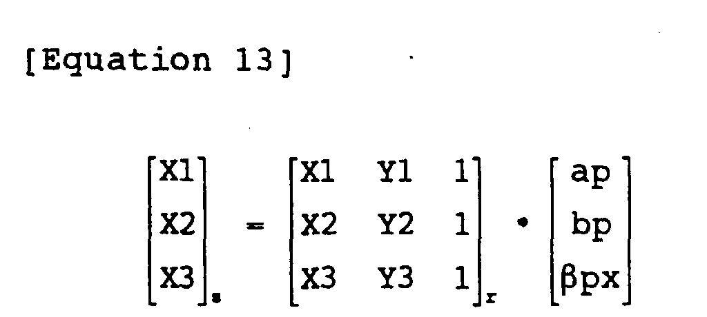
- the position based on the robot coordinate system r can be also determined not by the board camera 15, but by the conversion from the reference board coordinate system s. In this case, the position based on the robot coordinate system r is determined from the equation (13) ( it is required that the position of the recognition hole is accurately given on the reference board coordinate system s).
- a recognition target having many points which can be used as measurement points such as QFP is mounted under suction by the mounting head.
- the recognition of the recognition target is carried out by the part camera 14 while the mounting head 13 is rotated at an angular interval of several degrees by 360 degrees.
- the part camera 14 is moved to the position of the robot coordinate system which is obtained by substituting (0,0,1) p into the equation (7), whereby the center of the mounting head 13 is moved substantially to the center of the visual field of the part camera 14.
- the recognition target in the visual field of the part camera 14 and the position of the rotational center of the mounting head 13 are determined.
- the recognition result of an electrical part by the part camera 14 is directly used as a rotational radius in the rotation correction step of the electrical part.
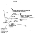
- the fixed camera coordinate system f, the board camera coordinate system p and the reference board coordinate system s are calibrated by the robot coordinate system r as shown in Fig. 5, and the conversion between each coordinate system and the robot coordinate system r is carried out on the following equations, and then the calibration is completed.
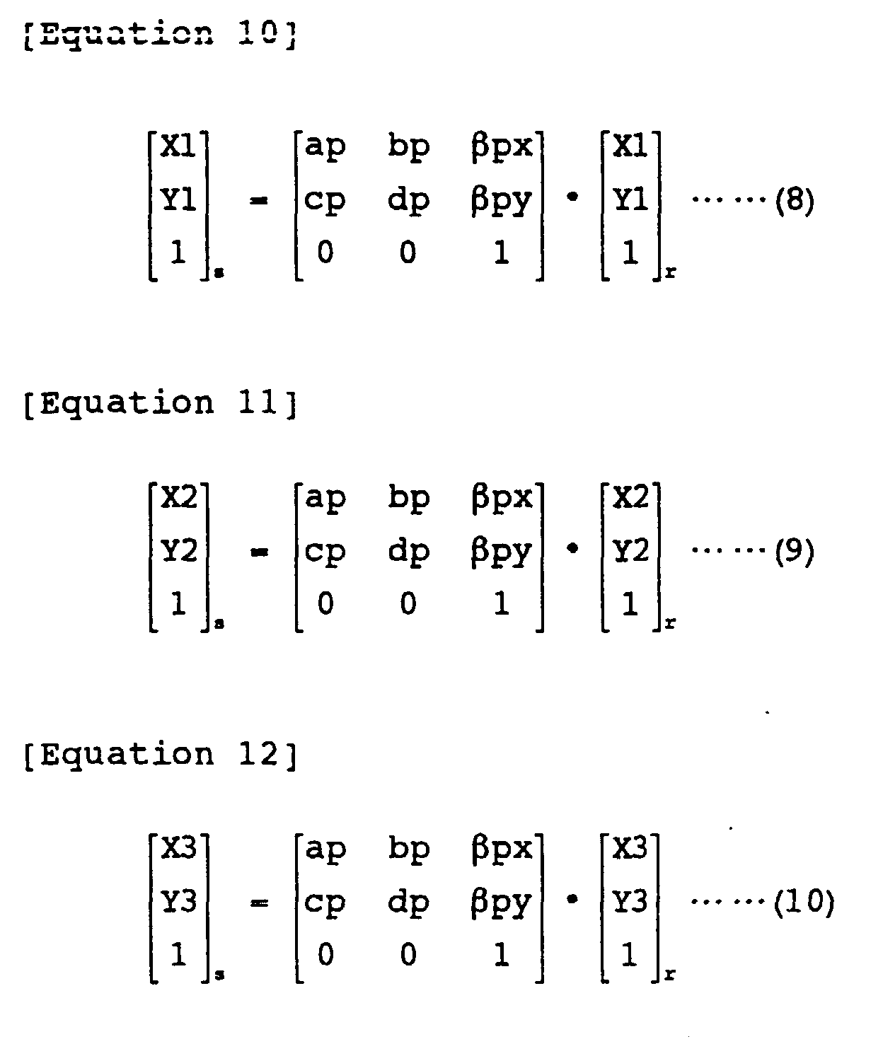
- the fixed camera coordinate system f, for the reference board coordinate system s, and for the board camera coordinate system p Subscripts represent the following coordinate systems.
- an alignment mark on the mounting board 11 is first recognized by the board camera 15 mounted on the mounting head 13 in step ST11.
- the mounting board 11 is fed to and set up at a predetermined position on the support table 11, and then two known alignment marks (Xn1, Yn1) nc , (Xn2, Yn2) nc are recognized in the NC coordinate system nc by the board camera 15.
- the board camera 15 is moved to the recognition position, the reference board coordinate system s is used.
- step ST12 a mount target electrical part in the part supply portion 12 is mounted under suction by the suction nozzle of the mounting head 13, and in step ST13 the electrical part concerned is positioned onto the fixed camera 14 and then recognized by the fixed camera 14.
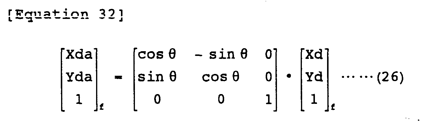
- the correction angle ⁇ is represented as follows, wherein the inclination of the electrical part when it is actually mounted under suction and recognized by the fixed camera is represented by ⁇ d, and the position of the electrical part is represented by (Xd,Yd) f , and a target angle is represented ⁇ a.
- the position (Xd, Yd) f is also displaced when the electrical part concerned is rotated by the correction angle ⁇ as shown in Fig. 7. Since the rotational center position is coincident with the screen center of the fixed camera 14 and the origin of the fixed camera 14 as shown in Fig. 8, on the assumption of this coincidence, the position-corrected position (Xda, Yda) f when the electrical part is subjected to the rotational correction on the fixed camera coordinate system f is given from the following equation:
- the part mounting position is given on the robot coordinate system r as follows: (Xn,Yn) nc represents the part mount position based on the NC coordinate system. Further, the position of the part on the robot coordinate system after the mount angle adjustment is given as follows: (Xda, Yda) f represents the position of the part after the rotational correction which contains the inclination of the board on the fixed camera coordinate system f.
- step ST15 the mounting head is moved to the mount position given from the equation (30), whereby the electrical part concerned is moved to a desired mount position of the mounting board 11 and the electrical part is mounted on the mounting board 11.
- each coordinate system is calibrated by the coordinate system of the mounting head, whereby the calibration of the part mounting apparatus can be systematized. Therefore, the final mounting precision can be easily estimated at the design step of the part mounting apparatus, and desired mounting precision can be surely achieved.
- the calibration method is widely usable to support new models, and thus the development time of the new models of the part mounting apparatus can be shorted and the developing cost can be reduced.
- repetitive positioning precision is required with respect to the position of the mounting head and the rotational angle of the part on the basis of the mounting head, and repetitive precision is required with respect to the image recognition of the fixed camera 14 and the board camera 15. Further, it is unnecessary that the two coordinate axes of the robot coordinate system intersect to each other at 90 degrees, however, linearity of the axes is required to be ensured.
- the coordinate axis of each coordinate system may face in any direction, however, the coordinate planes on which the two coordinate axes of the respective coordinate systems are located must be parallel to each other.
- the mounting head recognizes the mounting board and mounts a part thereon.
- the present invention is not limited to this embodiment, and the present invention may be applied to a part mounting apparatus in which a board is located on a mounting head, a board camera is fixedly disposed, and the mounting head moves the mounting board relatively to a fixedly disposed electrical part, whereby the electrical part concerned is relatively moved to a predetermined position of the mounting board.
- the mounting head is designed in a so-called XY type in which the mounting head is moved in the XY directions.
- the present invention is not limited to this embodiment, and it may be designed in a so-called SCARA type or vertical joint type. In this case, the calibration of each coordinate system is carried out for XY coordinate which is virtually constructed.
- the fixed camera and the board camera comprising CCD cameras are used as the part recognition portion and the board recognition portion in order to recognize the electrical part and the mounting board.
- a sensor such as an LED sensor or a laser sensor may be used insofar as it can detect the coordinate position and rotation of the coordinate system.
- a widely usable calibration method which can enhance the mounting precision and can be easily developed by systematizing the calibration of the mounting position of the mounting head to the mounting board.
Landscapes
- Engineering & Computer Science (AREA)
- Manufacturing & Machinery (AREA)
- Microelectronics & Electronic Packaging (AREA)
- Operations Research (AREA)
- Supply And Installment Of Electrical Components (AREA)
Abstract
Description


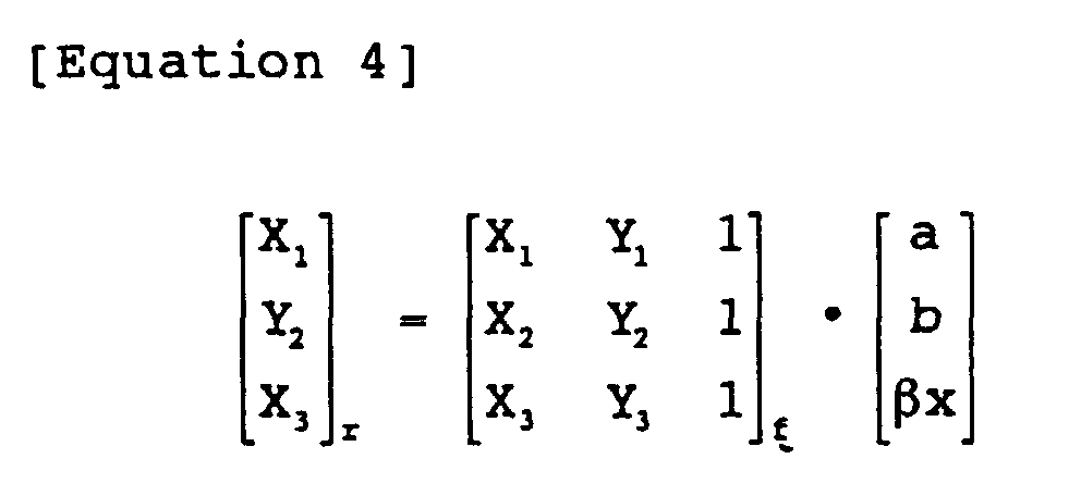




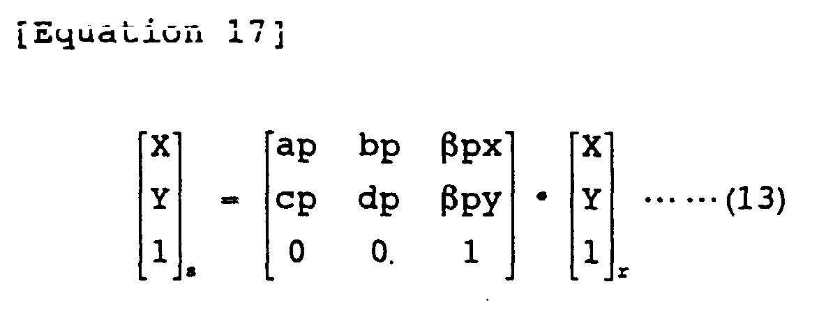
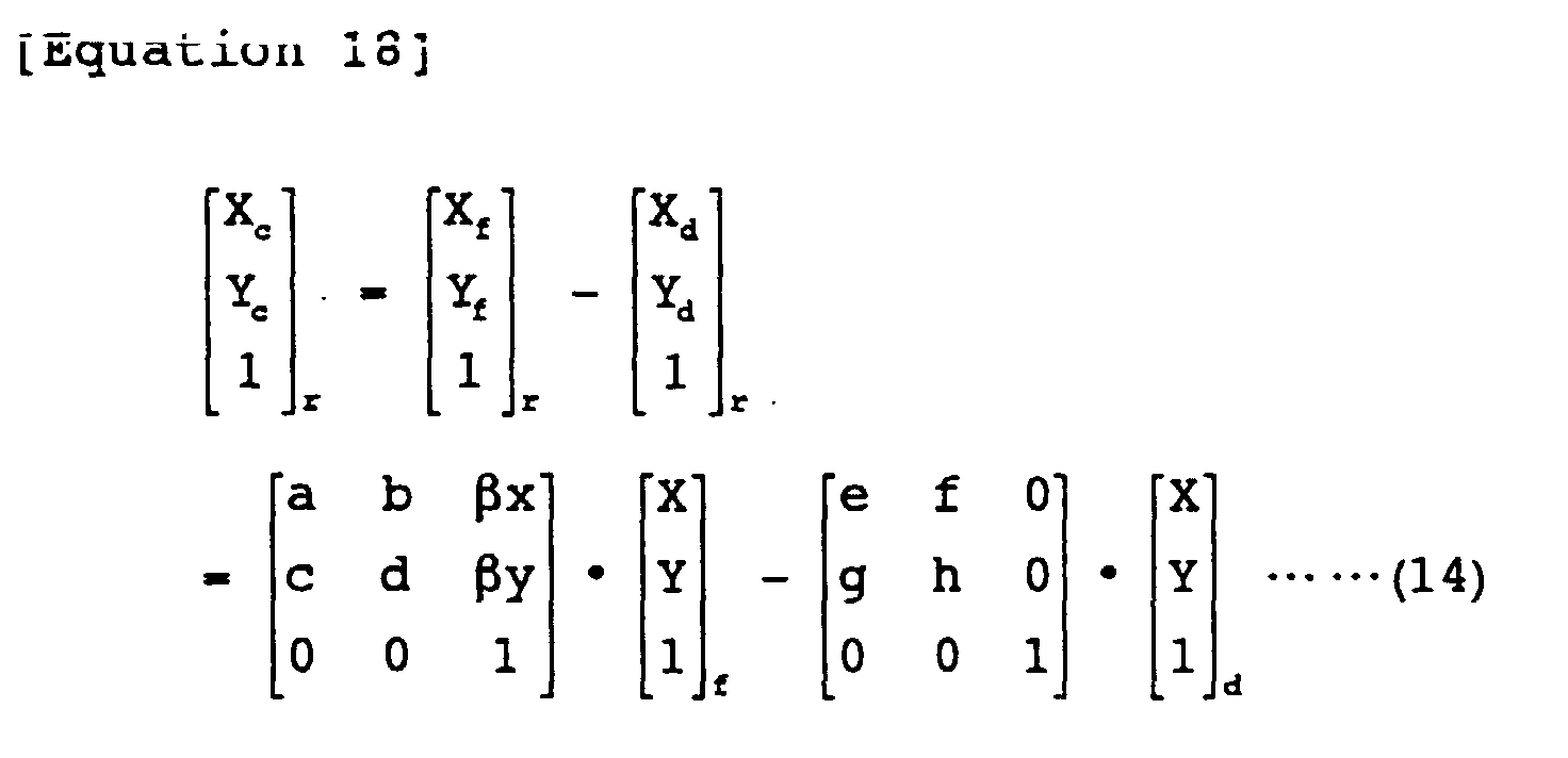
For the fixed camera coordinate system f,
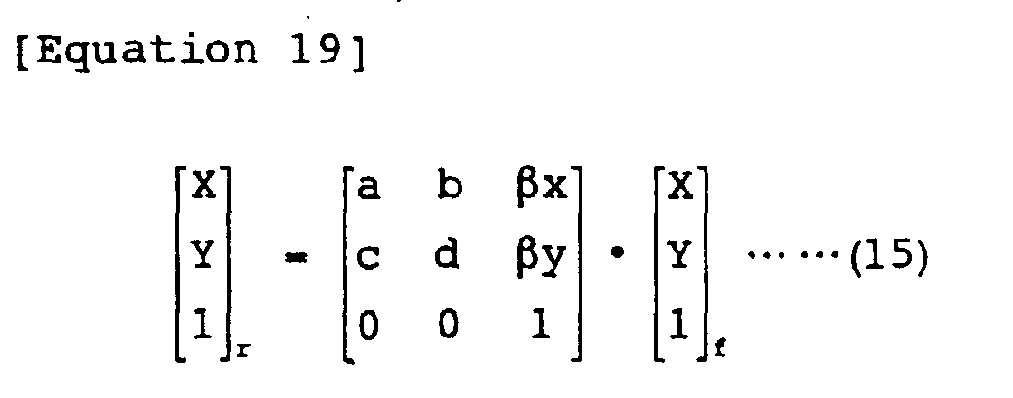


- r:
- XY robot coordinate system
- p:
- camera coordinate system for board recognition
- s:
- reference board coordinate system
- f:
- camera coordinate system for part recognition
- βp:
- the offset in origin between XY robot coordinate system and reference board coordinate system
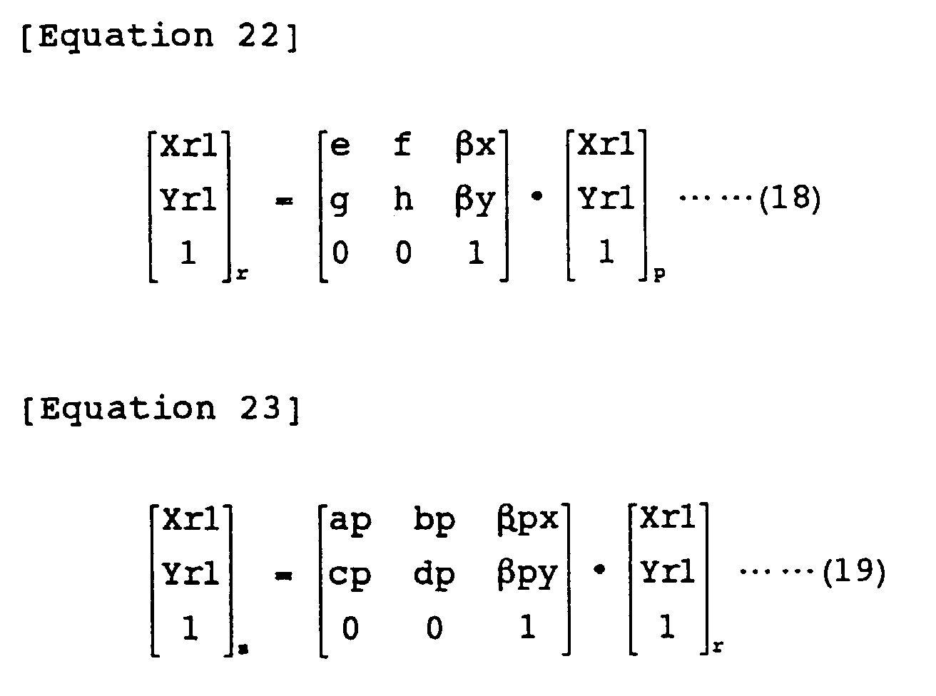


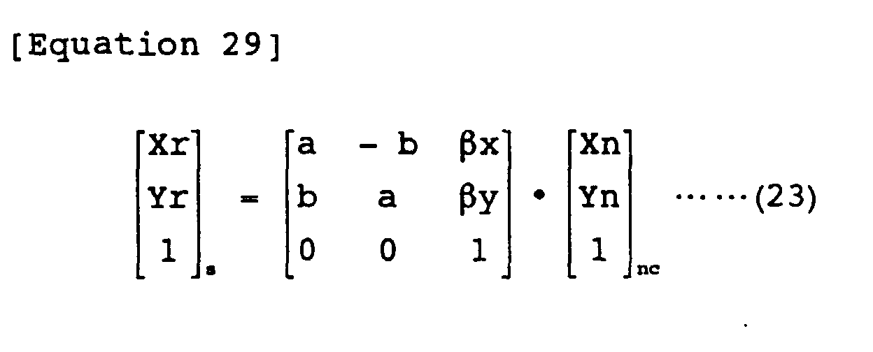
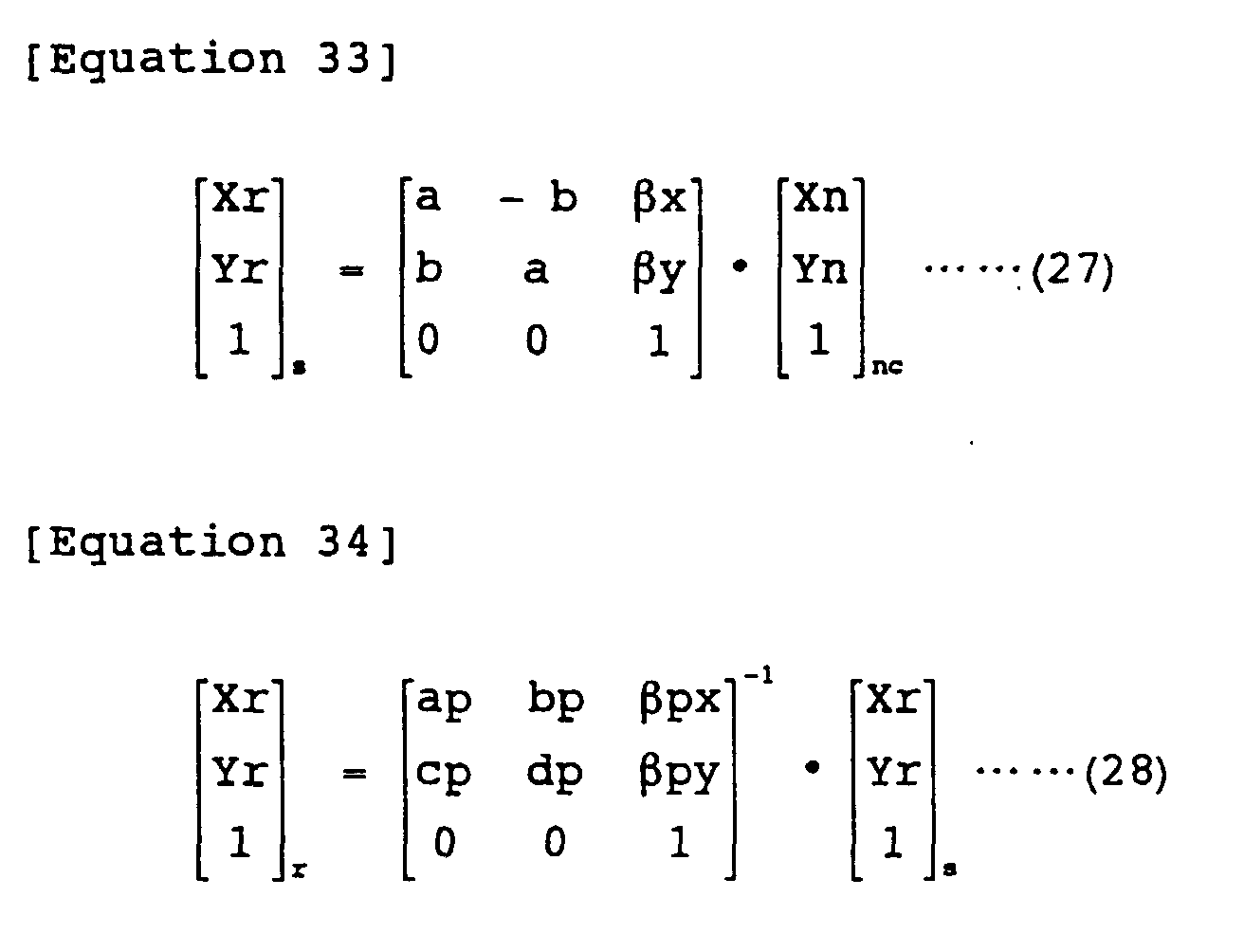
Further, the position of the part on the robot coordinate system after the mount angle adjustment is given as follows:


Claims (6)
- A calibrating method for a part mounting apparatus including a support table on which a mount board is supported, a part supply portion for successively supplying electrical parts, a mounting head for feeding an electrical part from the part supply portion to a predetermined position of the mount board on the support table, a part recognition portion which is fixedly disposed so as to detect the position of an electrical part in the part supply portion on the basis of image recognition, and a board recognition portion which is provided to the mounting head so as to detect the position of the mount board on the support table on the basis of image recognition, characterized by comprising:a first step for calibrating the coordinate system of said part recognition portion on the basis of the coordinate system of said mounting head;a second step for calibrating the coordinate system of said board recognition portion on the basis of the coordinate system of said mounting head;a third step for calibrating the coordinate system of a reference board on the basis of the coordinate system of said mounting head;a fourth step for correcting the origin of the coordinate system of said part recognition portion on the basis of the coordinate system of said mounting head; anda fifth step for calculating the rotational center position of said mounting head.
- The calibrating method as claimed in claim 1, wherein said first step mounts a recognition target by said mounting head and recognizes the recognition target by said part recognition portion on the basis of three points which are not located on any straight line on the plane parallel to the board surface, thereby calibrating the coordinate system of said part recognition portion on the basis of the coordinate system of said mounting head.
- The calibrating method as claimed in claim 1, wherein said second step recognizes the fixed point on said board by said board recognition portion on the basis of three points which are not located on any straight line on the plane parallel to the board surface of said board recognition portion, thereby calibrating the coordinate system of said board recognition portion on the basis of the coordinate system of said mounting head.
- The calibrating method as claimed in claim 1, wherein said third step recognizes, by said board recognition portion, three points which are not located on a known straight line on a reference board supported on said support table, thereby calibrating the coordinate system of the reference board on the basis of the coordinate system of said mounting head.
- The calibrating method as claimed in claim 1, wherein said fourth step recognizes one recognition hole fixedly disposed on a board jig on the basis of the coordinate system of a fixed recognition portion and a part recognition portion or a reference board, thereby calibrating the origin of the coordinate system of said fixed recognition portion on the basis of the coordinate system of said mounting head.
- The calibrating method as claimed in claim 1, wherein said fifth step mounts a recognition target by said mounting head and recognizes the recognition target while rotating the recognition target around the vertical axis by every predetermined angle, thereby calibrating the rotational center position of said mounting head in the coordinate system of said part recognition portion.
Applications Claiming Priority (2)
| Application Number | Priority Date | Filing Date | Title |
|---|---|---|---|
| JP11184304A JP2001015992A (en) | 1999-06-29 | 1999-06-29 | Calibration method for component mounting equipment |
| JP18430499 | 1999-06-29 |
Publications (2)
| Publication Number | Publication Date |
|---|---|
| EP1065917A2 true EP1065917A2 (en) | 2001-01-03 |
| EP1065917A3 EP1065917A3 (en) | 2002-01-02 |
Family
ID=16151001
Family Applications (1)
| Application Number | Title | Priority Date | Filing Date |
|---|---|---|---|
| EP00113695A Withdrawn EP1065917A3 (en) | 1999-06-29 | 2000-06-28 | Calibrating method for part mounting apparatus |
Country Status (2)
| Country | Link |
|---|---|
| EP (1) | EP1065917A3 (en) |
| JP (1) | JP2001015992A (en) |
Cited By (3)
| Publication number | Priority date | Publication date | Assignee | Title |
|---|---|---|---|---|
| WO2009047214A3 (en) * | 2007-10-09 | 2009-08-27 | Oerlikon Assembly Equipment Ag, Steinhausen | Method for picking up semiconductor chips from a wafer table and mounting the removed semiconductor chips on a substrate |
| CN101861637B (en) * | 2007-10-09 | 2012-07-18 | Esec公司 | Method for picking up semiconductor chips from a wafer table and method for mounting removed semiconductor chips on a substrate |
| EP2989872B1 (en) * | 2013-04-25 | 2020-08-12 | Finetech GmbH & Co. KG | Placement apparatus and placement method |
Families Citing this family (1)
| Publication number | Priority date | Publication date | Assignee | Title |
|---|---|---|---|---|
| EP3771310B1 (en) * | 2018-03-23 | 2023-09-20 | Fuji Corporation | Component-mounting device |
Family Cites Families (5)
| Publication number | Priority date | Publication date | Assignee | Title |
|---|---|---|---|---|
| JPS61188056A (en) * | 1985-02-16 | 1986-08-21 | Nec Home Electronics Ltd | Positioning system between printed circuit board and machining device |
| US4738025A (en) * | 1986-12-23 | 1988-04-19 | Northern Telecom Limited | Automated apparatus and method for positioning multicontact component |
| JP2707548B2 (en) * | 1987-05-30 | 1998-01-28 | ソニー株式会社 | Coordinate correction method for visual recognition device |
| KR0140167B1 (en) * | 1994-12-28 | 1998-08-17 | 배순훈 | Method for correcting camera deviation angle of chip mount system |
| JP3907786B2 (en) * | 1997-06-16 | 2007-04-18 | 松下電器産業株式会社 | Electronic component mounting method and apparatus |
-
1999
- 1999-06-29 JP JP11184304A patent/JP2001015992A/en active Pending
-
2000
- 2000-06-28 EP EP00113695A patent/EP1065917A3/en not_active Withdrawn
Cited By (6)
| Publication number | Priority date | Publication date | Assignee | Title |
|---|---|---|---|---|
| WO2009047214A3 (en) * | 2007-10-09 | 2009-08-27 | Oerlikon Assembly Equipment Ag, Steinhausen | Method for picking up semiconductor chips from a wafer table and mounting the removed semiconductor chips on a substrate |
| US8133823B2 (en) | 2007-10-09 | 2012-03-13 | Oerlikon Assembly Equipment Ag, Steinhausen | Method for picking up semiconductor chips from a wafer table and method for mounting semiconductor chips on a substrate |
| CN101861637B (en) * | 2007-10-09 | 2012-07-18 | Esec公司 | Method for picking up semiconductor chips from a wafer table and method for mounting removed semiconductor chips on a substrate |
| DE112008002467B4 (en) * | 2007-10-09 | 2013-08-22 | Esec Ag | Method for the removal of semiconductor chips from a wafer table and the mounting of the semiconductor chips on a substrate |
| TWI464820B (en) * | 2007-10-09 | 2014-12-11 | 歐瑞康組件設備史坦胡森有限公司 | Method for mounting a semiconductor wafer on a substrate |
| EP2989872B1 (en) * | 2013-04-25 | 2020-08-12 | Finetech GmbH & Co. KG | Placement apparatus and placement method |
Also Published As
| Publication number | Publication date |
|---|---|
| EP1065917A3 (en) | 2002-01-02 |
| JP2001015992A (en) | 2001-01-19 |
Similar Documents
| Publication | Publication Date | Title |
|---|---|---|
| EP0489919B1 (en) | Calibration system of visual sensor | |
| US6785404B1 (en) | Image positional relation correction apparatus, steering supporting apparatus provided with the image positional relation correction apparatus, and image positional relation correction method | |
| CN112297004B (en) | Control device for a robot device for controlling the position of a robot | |
| US20060106497A1 (en) | Carriage robot system and its controlling method | |
| EP0886465B1 (en) | Electronic components mounting method and apparatus | |
| EP1402967A1 (en) | Work positioning device | |
| JP2004530889A (en) | Automatic calibration positioning system | |
| JP2004530889A5 (en) | ||
| US6658313B1 (en) | Apparatus for adjusting the origins of module heads of a surface mounting apparatus and method therefor | |
| US20050005463A1 (en) | Self-calibrating position determination system and user interface | |
| JPH08132373A (en) | Coordinate system coupling method in robot-sensor system | |
| JP3466340B2 (en) | A 3D position and orientation calibration method for a self-contained traveling robot | |
| JPH0790494B2 (en) | Calibration method of visual sensor | |
| EP1065917A2 (en) | Calibrating method for part mounting apparatus | |
| JP6807450B2 (en) | Articulated robot parallelism determination method and articulated robot tilt adjustment device | |
| CN114571199A (en) | Screw locking machine and screw positioning method | |
| CN1318820C (en) | Correcting method for electronic part mounting device and device for using said method | |
| JP4405009B2 (en) | Calibration method of inspection machine with line sensor camera | |
| JPH09214198A (en) | Component suction state detection device for mounting machine | |
| JPH1011146A (en) | Stopping posture correction device for moving objects | |
| JP3286105B2 (en) | Mounting position correction method for mounting machine | |
| JPH06244595A (en) | Electronic parts mounting equipment | |
| JP3620868B2 (en) | Electronic component mounting apparatus and electronic component mounting method | |
| JP3499316B2 (en) | Calibration data detection method for mounting machine and mounting machine | |
| JPS63191589A (en) | Method of mounting part |
Legal Events
| Date | Code | Title | Description |
|---|---|---|---|
| PUAI | Public reference made under article 153(3) epc to a published international application that has entered the european phase |
Free format text: ORIGINAL CODE: 0009012 |
|
| AK | Designated contracting states |
Kind code of ref document: A2 Designated state(s): AT BE CH CY DE DK ES FI FR GB GR IE IT LI LU MC NL PT SE Kind code of ref document: A2 Designated state(s): DE FR GB |
|
| AX | Request for extension of the european patent |
Free format text: AL;LT;LV;MK;RO;SI |
|
| PUAL | Search report despatched |
Free format text: ORIGINAL CODE: 0009013 |
|
| AK | Designated contracting states |
Kind code of ref document: A3 Designated state(s): AT BE CH CY DE DK ES FI FR GB GR IE IT LI LU MC NL PT SE |
|
| AX | Request for extension of the european patent |
Free format text: AL;LT;LV;MK;RO;SI |
|
| 17P | Request for examination filed |
Effective date: 20020605 |
|
| AKX | Designation fees paid |
Free format text: DE FR GB |
|
| 17Q | First examination report despatched |
Effective date: 20021127 |
|
| GRAP | Despatch of communication of intention to grant a patent |
Free format text: ORIGINAL CODE: EPIDOSNIGR1 |
|
| GRAS | Grant fee paid |
Free format text: ORIGINAL CODE: EPIDOSNIGR3 |
|
| STAA | Information on the status of an ep patent application or granted ep patent |
Free format text: STATUS: THE APPLICATION HAS BEEN WITHDRAWN |
|
| 18W | Application withdrawn |
Effective date: 20031211 |