EP1065535A2 - Apparatus for fabricating apodized fiber grating - Google Patents
Apparatus for fabricating apodized fiber grating Download PDFInfo
- Publication number
- EP1065535A2 EP1065535A2 EP00113502A EP00113502A EP1065535A2 EP 1065535 A2 EP1065535 A2 EP 1065535A2 EP 00113502 A EP00113502 A EP 00113502A EP 00113502 A EP00113502 A EP 00113502A EP 1065535 A2 EP1065535 A2 EP 1065535A2
- Authority
- EP
- European Patent Office
- Prior art keywords
- optical fiber
- gratings
- blocking device
- laser
- screen mask
- Prior art date
- Legal status (The legal status is an assumption and is not a legal conclusion. Google has not performed a legal analysis and makes no representation as to the accuracy of the status listed.)
- Ceased
Links
Images




Classifications
-
- G—PHYSICS
- G02—OPTICS
- G02B—OPTICAL ELEMENTS, SYSTEMS OR APPARATUS
- G02B6/00—Light guides; Structural details of arrangements comprising light guides and other optical elements, e.g. couplings
-
- G—PHYSICS
- G02—OPTICS
- G02B—OPTICAL ELEMENTS, SYSTEMS OR APPARATUS
- G02B6/00—Light guides; Structural details of arrangements comprising light guides and other optical elements, e.g. couplings
- G02B6/02—Optical fibres with cladding with or without a coating
- G02B6/02057—Optical fibres with cladding with or without a coating comprising gratings
- G02B6/02076—Refractive index modulation gratings, e.g. Bragg gratings
- G02B6/02123—Refractive index modulation gratings, e.g. Bragg gratings characterised by the method of manufacture of the grating
- G02B6/02133—Refractive index modulation gratings, e.g. Bragg gratings characterised by the method of manufacture of the grating using beam interference
- G02B6/02138—Refractive index modulation gratings, e.g. Bragg gratings characterised by the method of manufacture of the grating using beam interference based on illuminating a phase mask
-
- G—PHYSICS
- G02—OPTICS
- G02B—OPTICAL ELEMENTS, SYSTEMS OR APPARATUS
- G02B6/00—Light guides; Structural details of arrangements comprising light guides and other optical elements, e.g. couplings
- G02B6/02—Optical fibres with cladding with or without a coating
- G02B6/02057—Optical fibres with cladding with or without a coating comprising gratings
- G02B6/02076—Refractive index modulation gratings, e.g. Bragg gratings
- G02B6/0208—Refractive index modulation gratings, e.g. Bragg gratings characterised by their structure, wavelength response
- G02B6/02085—Refractive index modulation gratings, e.g. Bragg gratings characterised by their structure, wavelength response characterised by the grating profile, e.g. chirped, apodised, tilted, helical
Definitions
- the present invention relates generally to fiber gratings, and in particular, to an apparatus for fabricating apodized fiber gratings.
- WDM Widelength Division Multiplexing
- Fiber gratings satisfy the requirements of the optical filter, i.e., low loss, low polarization dependence, and high channel selectivity. Further, the cost effectiveness of the fiber gratings make them popular as an optical filter.
- This sidelobe can be reduced by apodizing the fiber grating such that the magnitude of a refractive index variation is decreased toward the ends of the fiber grating.
- Another one-dot-dashed line (b) in FIG. 11 indicates a variation in the refractive index of the apodized fiber grating.
- An apodized fiber grating refers to a fiber grating of which the refractive index increases or decreases toward the center or both ends.
- the apodized fiber grating shows minimized sidelobes in both a short wavelength band and a long wavelength band.
- apodization is effective in reducing sidelobe in a longer wavelength band, it has limitations in reducing sidelobe in a shorter wavelength band due to self-induced chirping of a fiber grating.
- the self-induced chirping is attributed to an inconstant average refractive index of the fiber grating as shown in FIG. 2. Accordingly, the average refractive index should be made constant with respect to grating length in order to reduce sidelobe which arises from the self-induced chirping.
- the overlap writing method is called an interference method, in which apodization is achieved by writing gratings superimposed on other gratings of different periods and sizes in an optical fiber.
- gratings are written on an optical fiber while a tensile force is applied to the optical fiber using a PZT.
- the optical fiber or a phase mask is vibrated for a desired length in the length direction of the optical fiber by the use of the PZT.
- apodized gratings are written by scanning an optical fiber covered with a phase mask with UV (Ultra Violet) light lengthwise with different light intensities at different scanning rates.
- a spatial filter operates based on light interference.
- the intensity of interference light passed through a diffraction slit exhibits a Gaussian distribution.
- a spatial filter with a different transmission is disposed before a phase mask along the length direction of an optical fiber and UV light is projected onto the phase mask.
- phase mask when a fiber grating is fabricated using a phase mask, the phase mask should be fabricated by focused ion beam implantation and wet etching to have an effective profile. A new phase mask is needed at every change in apodization conditions. Therefore, this method is not effective in terms of cost and flexibility.
- the method of scanning an optical fiber lengthwise with UV light at a controlled light intensity has the distinctive shortcomings of long fabrication time and bad reproducibility.
- the apodizing phase mask using method is not effective in terms of cost and flexibility since a phase mask is difficult to fabricate and a new phase mask is needed at every change in apodization conditions.
- the beam scanning method has the disadvantages of difficult fabrication, long fabrication time, and bad reproducibility.
- an object of the present invention to provide an apparatus for fabricating an apodized fiber grating readily using a beam splitter and a screen mask.
- a UV (Ultra Violet) laser emits a UV laser beam
- a beam splitter splits the UV laser beam emitted from the UV laser into two beams
- a plurality of mirrors form light paths to concurrently project the split beams onto an optical fiber from two directions by reflecting the split beams
- a phase mask passes the reflected beams therethrough in such a way to form gratings in the optical fiber in a predetermined period
- a first blocking device is disposed between the phase mask and one of the mirrors, progressively blocks one of the two beams from being projected toward the optical fiber from one direction, and provides apodization to the formed gratings
- a second blocking device which is mobile and opposite to the first blocking device with respect to the optical fiber, progressively blocks the other beam from being projected toward the optical fiber from another direction and provides apodization to the formed gratings, so that an average refractive index variation is constant across the whole
- a first UV laser emits a first UV laser beam toward an optical fiber from one direction and a second UV laser emits a second UV laser beam toward the optical fiber from an opposite direction.
- a phase mask forms gratings in the optical fiber in a predetermined period by reinforcement and interference of the first UV laser beam.
- a first blocking device disposed between the first UV laser and the phase mask, progressively blocks one of the beams from being projected to the optical fiber and thus provides apodization to the formed gratings
- a second blocking device opposite to the first blocking device with respect to the optical fiber, progressively blocks the other beam from being projected to the optical fiber and provides apodization to the formed gratings, so that an average refractive index variation is constant across the whole gratings.
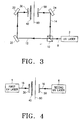
- FIG. 3 schematically illustrates the configuration of an apodized fiber grating fabricating apparatus according to a preferred embodiment of the present invention.
- the apodized optical fiber grating fabricating apparatus includes a UV laser 2 as a light source, a beam splitter 10 for splitting a beam 8 emitted from the UV laser 2, a plurality of mirrors 20, 22, and 24 for controlling the direction of beams projected from the beam splitter 10, first and second mobile screen masks 30 and 50 to be used for apodizing a grating when the beams reflected from the mirrors 20, 22, and 24 are projected onto an optical fiber 60, and a phase mask 40 for generating the grating by interference and reinforcement of the projected light.
- a UV laser 2 as a light source
- a beam splitter 10 for splitting a beam 8 emitted from the UV laser 2
- a plurality of mirrors 20, 22, and 24 for controlling the direction of beams projected from the beam splitter 10
- first and second mobile screen masks 30 and 50 to be used for apodizing a grating when the beams reflected from the mirrors 20, 22, and 24 are projected onto an optical fiber 60
- a phase mask 40 for generating
- the beam splitter 10 splits the beam 8 emitted from the UV laser 2 into two beams 12 and 14.
- One 12 of the beams is reflected from the mirrors 20 and 22 and reaches the first screen mask 30 and the other beam 14 is reflected from the mirror 24 and reaches the second screen mask 50.
- the two beams 12 and 14 travel mutually orthogonally from the beam splitter 10.
- the beam 12 is sequentially reflected from the first and second mirrors 20 and 22 and impinges on the phase mask 40.
- the first mask 30 and second mask 50 are disposed face to face at both sides of the optical fiber 60.
- the phase mask 40 is interposed between the first screen mask 30 and the optical fiber 60.
- the beam 12 is projected onto the phase mask 40 and forms a plurality of gratings in the optical fiber 60 in a predetermined period by reinforcement and interference of light as the beam 12 passes through the phase mask 40.
- the beam 14 is reflected from the third mirror 24 and reaches the second screen mask 50. Consequently, the beam 8 emitted from the UV laser 2 is concurrently projected onto the first and second screen masks 30 and 50 through the beam splitter 10 and the mirrors 20, 22, and 24.
- the first and second screen masks 30 and 50 are mobile for apodization of the gratings according to the present invention.
- FIG. 4 is a schematic view of an apodized fiber grating fabricating apparatus according to another preferred embodiment of the present invention. While the apodized fiber grating fabricating apparatus of FIG. 3 projects a beam from a UV laser onto an optical fiber in two directions using a beam splitter and a plurality of mirrors, the one shown in FIG. 4 projects a beam onto an optical fiber in two directions using two UV lasers.
- the apodized fiber grating fabricating apparatus includes a first UV laser 4 disposed at one side of the optical fiber 60, a second UV laser 6 disposed at the other side of the optical fiber 60, the phase mask 40 through which a beam 16 emitted from the first UV laser 4 passes to write a grating in the optical fiber 60 utilizing light reinforcement and interference, the first screen mask 30 over the phase mask 40 to apodize the fiber grating, and the second screen mask 50 between the second UV laser 6 and the optical fiber 60 to apodize the optical fiber grating.
- the first and second screen masks 30 and 50 face each other a predetermined distance apart with the interposition of the optical fiber 60.
- the first and second screen masks 30 and 50 are mobile for apodization of the written grating.
- the beam 16 emitted from the first UV laser 4 is projected onto the phase mask 40 and forms gratings in the optical fiber 60 in a predetermined period by light reinforcement and interference as it passes through the phase mask 40.
- the first and second screen masks 30 and 50 apodize the fabricated gratings as they are approaching each other.
- first and second screen masks 30 and 50 act to block beams and may be formed of any material as far as it can block the travel of beams.
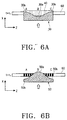
- an X axis represents the movement direction of the first and second screen masks 30 and 50 and a Z axis, the length direction of the optical fiber 60.
- Reference symbol ⁇ also indicates the movement direction of the first and second screen masks 30 and 50.
- Reference character L indicates a length of the optical fiber 60 for which gratings are written, reference character B indicates the mid point of L, and reference characters A and C indicate both ends of L.
- the first screen mask 30 includes a concave portion 30a at the center and convex portions 30b that are protruded gradually from the concave portion 30a towards both ends of the first screen mask 30.
- the second screen mask 50 includes a convex portion 50a at the center and concave portions 50b that are sunken gradually from the center towards both ends of the second screen mask 50.
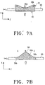
- the configurations of the first and second screen masks 30 and 50 in FIGs. 5A to 7B are merely exemplary applications, and it is clear that many variations can be made as far as they are used for apodization of written gratings. for example, the first and second screen masks 30 and 50 can be shaped into steps.
- a first laser beam emitted from the first UV laser is all projected onto the phase mask 40 and forms a grating in the optical fiber 60 in a predetermined period through the phase mask 40, as shown in FIG. 5A.
- the first screen mask 30 moves in a direction as indicated by ⁇ until it covers portions A and C of the optical fiber 60. Therefore, the portions A and C are excluded from irradiation of the first UV laser beam emitted from the first UV laser whereas a portion B of the optical fiber 60 is irradiated with the first UV laser beam for a predetermined time.
- FIG. 8 is a graph showing a variation in the refractive index with respect to the length direction of an optical fiber when gratings are formed in the optical fiber using the first screen mask.
- An X axis represents the variation of the refractive index and a Z axis, the length direction of the optical fiber.
- An apodized fiber grating experiences a greater variation in refractive index as it is nearer to the portion B of the optical fiber. On the contrary, the refractive index is less changed as an apodized grating is formed nearer to the portion A or C.
- the second screen mask 50 moves in a direction as indicated by ⁇ until the portion B of the optical fiber is gradually covered and excluded from irradiation of the second UV laser beam. Meanwhile, the second UV laser beam is projected onto the portions A and C of the optical fiber 60 for a predetermined time.
- FIG. 9 is a graph showing a variations in the refractive index with respect to the length direction of an optical fiber when gratings are formed in the optical fiber using the second screen mask.
- An X axis represents the variation of the refractive index and a Z axis, the length direction of the optical fiber.
- An apodized fiber grating experiences a greater variation in refractive index as it is nearer to the portion A or C of the optical fiber. On the contrary, the refractive index is less changed as an apodized grating is formed nearer to the portion B.
- FIG. 10 is a graph showing a variations in refractive index in the length direction of a fiber grating when the grating is written in an optical fiber by projecting a UV laser beam onto the optical fiber from two directions, moving the first and second screen masks 30 and 50 concurrently.
- Apodization is achieved in the grating by setting an average refractive index to be constant along the length of the fiber grating as shown in FIG. 10, and sidelobes in short and long wavelength bands are minimized as shown in FIG. 11.
- the one-dot-dashed line (a) indicates the reflective spectrum of a general optical fiber fabricated using a uniform mask as shown in FIG. 1.
- Another one-dot-dashed line (b) indicates the reflective spectrum of an apodized fiber grating of which the refractive index varies as shown in FIG. 2. As noted from (b), it is difficult to minimize sidelobe in a short wavelength band.
- a solid line (c) indicates the reflective spectrum of an apodized fiber grating at wavelengths according to the present invention. Sidelobes in short and long wavelength bands are reduced.
- an apodized fiber grating fabricating apparatus of the present invention forms apodized fiber gratings readily using a beam splitter and screen masks in addition to an existing optical equipment and phase mask, instead of separately procuring a new apodizing phase mask at every change in apodization conditions, or the beam scanning method having the disadvantages of difficult fabrication, long fabrication time, and bad reproducibility. Further, an apodized fiber grating can be written easily by the use of two UV lasers.
- the present invention has been described in the context with an apodized fiber grating fabricating apparatus having two screen masks as beam blocking means, but the number of the screen masks is not limited so long as an average refractive index variation is constant over the entire apodized fiber gratings.
- an apodized fiber grating fabricating apparatus of the present invention forms apodized fiber gratings readily using a beam splitter and screen masks in addition to an existing optical equipment and phase mask, instead of separately procuring a new apodizing phase mask at every change in apodization conditions, or the beam scanning method having the disadvantages of difficult fabrication, long fabrication time, and bad reproducibility.
Landscapes
- Physics & Mathematics (AREA)
- General Physics & Mathematics (AREA)
- Optics & Photonics (AREA)
- Engineering & Computer Science (AREA)
- Manufacturing & Machinery (AREA)
- Diffracting Gratings Or Hologram Optical Elements (AREA)
- Optical Fibers, Optical Fiber Cores, And Optical Fiber Bundles (AREA)
- Treatment Of Fiber Materials (AREA)
Abstract
Description
Claims (10)
- An apparatus for fabricating an apodized fiber grating, comprising:a UV (Ultra Violet) laser for emitting a UV laser beam;a beam splitter for splitting the UV laser beam emitted from the UV laser into two beams;a plurality of mirrors for forming light paths to concurrently project the split beams onto an optical fiber from two directions by reflecting the split beams;a phase mask for passing the reflected beams to form gratings in the optical fiber in a predetermined period;a first blocking device between the phase mask and one of the mirrors, for progressively blocking one of the two beams from being projected toward the optical fiber from one direction and providing apodization to the formed gratings; anda second blocking device which is mobile and opposite to the first blocking device with respect to the optical fiber, for progressively blocking the other beam from being projected toward the optical fiber from another direction and providing apodization to the formed gratings, so that an average refractive index variation is constant across the whole gratings.
- The apparatus of claim 1, wherein the first blocking device is a first screen mask.
- The apparatus of claim 2, wherein the first screen mask includes:a concave portion at the center, for providing apodization to the formed gratings; andtwo convex portions gradually protruded from the concave portion toward both ends of the first screen mask.
- The apparatus of claim 1, wherein the second blocking device is a second screen mask.
- The apparatus of claim 4, wherein the second screen mask includes:a convex portion at the center; andtwo concave portions gradually sunken from the convex portion toward both ends of the second screen mask.
- An apparatus for fabricating an apodized fiber grating, comprising:a first UV laser for emitting a first UV laser beam toward an optical fiber from one direction;a second UV laser for emitting a second UV laser beam toward the optical fiber from an opposite direction;a phase mask for forming gratings in the optical fiber in a predetermined period by reinforcement and interference of the first UV laser beam;a first blocking device between the first UV laser and the phase mask, for progressively blocking one of the beams from being projected to the optical fiber and thus providing apodization to the formed gratings; anda second blocking device opposite to the first blocking device with respect to the optical fiber, for progressively blocking the other beam from being projected to the optical fiber and providing apodization to the formed gratings, so that an average refractive index variation is constant across the whole gratings.
- The apparatus of claim 6, wherein the first blocking device is a first screen mask.
- The apparatus of claim 7, wherein the first screen mask includes:a concave portion at the center, for providing apodization to the formed gratings; andtwo convex portions gradually protruded from the concave portion toward both ends of the first screen mask.
- The apparatus of claim 6, wherein the second blocking device is a second screen mask.
- The apparatus of claim 9, wherein the second screen mask includes:a convex portion at the center; andtwo concave portions gradually sunken from the convex portion toward both ends of the second screen mask.
Applications Claiming Priority (2)
| Application Number | Priority Date | Filing Date | Title |
|---|---|---|---|
| KR1019990026671A KR100334812B1 (en) | 1999-07-02 | 1999-07-02 | Apodized fiber grating fabricating system |
| KR9926671 | 1999-07-02 |
Publications (2)
| Publication Number | Publication Date |
|---|---|
| EP1065535A2 true EP1065535A2 (en) | 2001-01-03 |
| EP1065535A3 EP1065535A3 (en) | 2002-04-24 |
Family
ID=19599100
Family Applications (1)
| Application Number | Title | Priority Date | Filing Date |
|---|---|---|---|
| EP00113502A Ceased EP1065535A3 (en) | 1999-07-02 | 2000-06-26 | Apparatus for fabricating apodized fiber grating |
Country Status (5)
| Country | Link |
|---|---|
| US (1) | US6707956B1 (en) |
| EP (1) | EP1065535A3 (en) |
| JP (1) | JP2001033612A (en) |
| KR (1) | KR100334812B1 (en) |
| CN (1) | CN1175292C (en) |
Cited By (3)
| Publication number | Priority date | Publication date | Assignee | Title |
|---|---|---|---|---|
| US6690860B2 (en) * | 2000-12-26 | 2004-02-10 | Mitsubishi Denki Kabushiki Kaisha | Method of manufacturing grating |
| US6963432B2 (en) | 2004-01-14 | 2005-11-08 | National Chiao Tung University | Fabrication of true apodized fiber Bragg grating using a new two-beam interferometer with polarization control |
| US7593609B2 (en) | 2007-10-26 | 2009-09-22 | National Chiao Tung University | Method for modulating refractive indices of optical fiber gratings |
Families Citing this family (10)
| Publication number | Priority date | Publication date | Assignee | Title |
|---|---|---|---|---|
| US6912331B2 (en) * | 2002-03-12 | 2005-06-28 | Cambrius Inc. | Periodic electromagnetic waveguide structures with controlled polarization properties |
| US6853772B2 (en) * | 2003-05-13 | 2005-02-08 | 3M Innovative Properties Company | Fiber grating writing interferometer with continuous wavelength tuning and chirp capability |
| US8685628B2 (en) * | 2006-04-24 | 2014-04-01 | Stc.Unm | Large area patterning using interferometric lithography |
| EP2454619A4 (en) | 2009-07-17 | 2016-01-06 | Hewlett Packard Development Co | Non-periodic grating reflectors with focusing power and methods for fabricatting the same |
| EP3709061B1 (en) | 2009-08-19 | 2022-12-14 | Lawrence Livermore National Security, LLC | Method of fabricating and method of using a diffractive optic |
| US8728719B2 (en) * | 2009-08-19 | 2014-05-20 | Lawrence Livermore National Security, Llc | Diffractive laser beam homogenizer including a photo-active material and method of fabricating the same |
| WO2011037563A1 (en) | 2009-09-23 | 2011-03-31 | Hewlett-Packard Development Company, L.P. | Optical devices based on diffraction gratings |
| US8952403B2 (en) | 2010-01-29 | 2015-02-10 | Hewlett-Packard Development, L.P. | Optical devices based on non-periodic sub-wavelength gratings |
| CN102955267A (en) * | 2012-11-08 | 2013-03-06 | 上海交通大学 | Silicon-based integrated chirped grating tunable optical delay line |
| CN118226572A (en) * | 2024-03-27 | 2024-06-21 | 武汉驿路通科技股份有限公司 | A multi-core optical fiber grating writing device |
Family Cites Families (7)
| Publication number | Priority date | Publication date | Assignee | Title |
|---|---|---|---|---|
| US5712715A (en) | 1992-12-23 | 1998-01-27 | Lucent Technologies Inc. | Optical transmission system with spatially-varying Bragg reflector |
| GB2302599B (en) * | 1995-06-20 | 1998-08-26 | Northern Telecom Ltd | Forming Bragg gratings in photosensitive optical waveguides |
| US5717799A (en) | 1996-10-10 | 1998-02-10 | Northern Telecom Limited | Optical waveguide filters |
| IT1292316B1 (en) | 1997-05-20 | 1999-01-29 | Cselt Centro Studi Lab Telecom | PROCEDURE AND DEVICE FOR THE CREATION OF FIBER BRAGG GRATINGS OR OPTICAL WAVE GUIDES. |
| FR2764394B1 (en) | 1997-06-10 | 1999-08-06 | France Telecom | PHOTO REGISTRATION BENCH FOR BRAGG NETWORKS |
| US5912999A (en) | 1997-10-02 | 1999-06-15 | Minnesota Mining And Manufacturing Company | Method for fabrication of in-line optical waveguide index grating of any length |
| US6035083A (en) | 1997-10-02 | 2000-03-07 | 3M Innovative Company | Method for writing arbitrary index perturbations in a wave-guiding structure |
-
1999
- 1999-07-02 KR KR1019990026671A patent/KR100334812B1/en not_active Expired - Fee Related
-
2000
- 2000-06-26 EP EP00113502A patent/EP1065535A3/en not_active Ceased
- 2000-06-26 JP JP2000191665A patent/JP2001033612A/en active Pending
- 2000-06-30 CN CNB001199889A patent/CN1175292C/en not_active Expired - Fee Related
- 2000-06-30 US US09/608,134 patent/US6707956B1/en not_active Expired - Fee Related
Cited By (3)
| Publication number | Priority date | Publication date | Assignee | Title |
|---|---|---|---|---|
| US6690860B2 (en) * | 2000-12-26 | 2004-02-10 | Mitsubishi Denki Kabushiki Kaisha | Method of manufacturing grating |
| US6963432B2 (en) | 2004-01-14 | 2005-11-08 | National Chiao Tung University | Fabrication of true apodized fiber Bragg grating using a new two-beam interferometer with polarization control |
| US7593609B2 (en) | 2007-10-26 | 2009-09-22 | National Chiao Tung University | Method for modulating refractive indices of optical fiber gratings |
Also Published As
| Publication number | Publication date |
|---|---|
| US6707956B1 (en) | 2004-03-16 |
| KR20010008723A (en) | 2001-02-05 |
| KR100334812B1 (en) | 2002-05-02 |
| EP1065535A3 (en) | 2002-04-24 |
| CN1292500A (en) | 2001-04-25 |
| CN1175292C (en) | 2004-11-10 |
| JP2001033612A (en) | 2001-02-09 |
Similar Documents
| Publication | Publication Date | Title |
|---|---|---|
| US6307679B1 (en) | Formation of a refractive index grating | |
| CN108700790B (en) | Optical deflector and lidar device | |
| EP1065535A2 (en) | Apparatus for fabricating apodized fiber grating | |
| US6188818B1 (en) | Low loss AWG demultiplexer with flat spectral response | |
| JP4177893B2 (en) | Optical waveguide grating | |
| US6021242A (en) | Diffraction grating type band-pass filter and method of making the same | |
| JP2678362B2 (en) | Optical signal processing method and optical element | |
| US6829067B2 (en) | Method and apparatus for implementing a multi-channel tunable filter | |
| EP1346241B1 (en) | Mems reconfigurable optical grating | |
| US6915044B2 (en) | Tunable talbot interferometers for fiber bragg grating writing | |
| EP1200857A4 (en) | METHOD OF REGISTERING DIFFRACTION NETWORK STRUCTURES | |
| EP0880042B1 (en) | A method of and a device for making bragg gratings in optical fibres or waveguides | |
| KR100490754B1 (en) | Variable optical attenuator with tunable wavelength dependence | |
| US6718083B2 (en) | Optical switch and router | |
| US20070280596A1 (en) | Method and System for Writing Fiber Bragg Grating Having Apodized Spectrum on Optical Fibers | |
| JP2002519742A (en) | Apodization of optical filters formed on photosensitive media | |
| US6751381B1 (en) | Embodying amplitude information into phase masks | |
| US6975794B2 (en) | Method and apparatus for fabricating a waveguide Bragg grating using pulsed light | |
| US20050095009A1 (en) | Optical assembly having cylindrical lenses and related method of modulating optical signals | |
| US20020075533A1 (en) | Method and device to fabricate holographic gratings with large area uniformity | |
| US20020018621A1 (en) | Optical fiber grating fabrication apparatus for minimizing diffraction effect | |
| US6417953B1 (en) | Laser optical system | |
| US20040252944A1 (en) | Apparatus and method of manufacturing optical waveguide type diffraction grating device | |
| JP2002228841A (en) | Chirped grating type optical filter and manufacturing method thereof | |
| JP2002243959A (en) | Optical wavelength multiplexing and branching device |
Legal Events
| Date | Code | Title | Description |
|---|---|---|---|
| PUAI | Public reference made under article 153(3) epc to a published international application that has entered the european phase |
Free format text: ORIGINAL CODE: 0009012 |
|
| 17P | Request for examination filed |
Effective date: 20000626 |
|
| AK | Designated contracting states |
Kind code of ref document: A2 Designated state(s): DE FR GB Kind code of ref document: A2 Designated state(s): AT BE CH CY DE DK ES FI FR GB GR IE IT LI LU MC NL PT SE |
|
| AX | Request for extension of the european patent |
Free format text: AL;LT;LV;MK;RO;SI |
|
| PUAL | Search report despatched |
Free format text: ORIGINAL CODE: 0009013 |
|
| RIC1 | Information provided on ipc code assigned before grant |
Free format text: 7G 02B 6/16 A, 7G 02B 6/34 B |
|
| AK | Designated contracting states |
Kind code of ref document: A3 Designated state(s): AT BE CH CY DE DK ES FI FR GB GR IE IT LI LU MC NL PT SE |
|
| AX | Request for extension of the european patent |
Free format text: AL;LT;LV;MK;RO;SI |
|
| 17Q | First examination report despatched |
Effective date: 20020808 |
|
| AKX | Designation fees paid |
Free format text: DE FR GB |
|
| STAA | Information on the status of an ep patent application or granted ep patent |
Free format text: STATUS: THE APPLICATION HAS BEEN REFUSED |
|
| 18R | Application refused |
Effective date: 20070603 |