EP1065030A2 - Determining when to replace a retaining ring used in substrate polishing operations - Google Patents
Determining when to replace a retaining ring used in substrate polishing operations Download PDFInfo
- Publication number
- EP1065030A2 EP1065030A2 EP00304382A EP00304382A EP1065030A2 EP 1065030 A2 EP1065030 A2 EP 1065030A2 EP 00304382 A EP00304382 A EP 00304382A EP 00304382 A EP00304382 A EP 00304382A EP 1065030 A2 EP1065030 A2 EP 1065030A2
- Authority
- EP
- European Patent Office
- Prior art keywords
- retaining ring
- wear
- substrate
- polishing
- wear marker
- Prior art date
- Legal status (The legal status is an assumption and is not a legal conclusion. Google has not performed a legal analysis and makes no representation as to the accuracy of the status listed.)
- Withdrawn
Links
Images


Classifications
-
- B—PERFORMING OPERATIONS; TRANSPORTING
- B24—GRINDING; POLISHING
- B24B—MACHINES, DEVICES, OR PROCESSES FOR GRINDING OR POLISHING; DRESSING OR CONDITIONING OF ABRADING SURFACES; FEEDING OF GRINDING, POLISHING, OR LAPPING AGENTS
- B24B37/00—Lapping machines or devices; Accessories
- B24B37/27—Work carriers
- B24B37/30—Work carriers for single side lapping of plane surfaces
- B24B37/32—Retaining rings
-
- B—PERFORMING OPERATIONS; TRANSPORTING
- B24—GRINDING; POLISHING
- B24B—MACHINES, DEVICES, OR PROCESSES FOR GRINDING OR POLISHING; DRESSING OR CONDITIONING OF ABRADING SURFACES; FEEDING OF GRINDING, POLISHING, OR LAPPING AGENTS
- B24B49/00—Measuring or gauging equipment for controlling the feed movement of the grinding tool or work; Arrangements of indicating or measuring equipment, e.g. for indicating the start of the grinding operation
- B24B49/12—Measuring or gauging equipment for controlling the feed movement of the grinding tool or work; Arrangements of indicating or measuring equipment, e.g. for indicating the start of the grinding operation involving optical means
Landscapes
- Engineering & Computer Science (AREA)
- Mechanical Engineering (AREA)
- Finish Polishing, Edge Sharpening, And Grinding By Specific Grinding Devices (AREA)
- Constituent Portions Of Griding Lathes, Driving, Sensing And Control (AREA)
- Mechanical Treatment Of Semiconductor (AREA)
Abstract
Description
- This invention relates to apparatus and methods for determining when to replace a retaining ring used in substrate polishing operations (e.g., chemical-mechanical polishing).
- Chemical mechanical polishing (CMP) is a process for planarizing the surface of a substrate (e.g., a semiconductor wafer). In a typical CMP process, a polishing surface of a polishing sheet (or pad) is covered with a slurry solution containing abrasive particles and one or more reactive chemicals. A substrate to be polished is held against the polishing surface by a carrier head in a recess defined by a substrate support surface and a retaining ring. The polishing surface and the carrier head are moved relative to one another causing the slurry to mechanically and chemically remove portions of the substrate surface.
- The retaining ring serves to hold the substrate in position on the carrier head and improves the uniformity of the polishing process. During this process, however, the retaining ring is exposed to the polishing action of the slurry and, after a period of time, a significant portion of the retaining ring will have been worn away. After a certain amount of material has worn away, its ability to retain the substrate in place and its beneficial impact on polishing uniformity diminishes. Eventually, the retaining ring must be replaced to avoid detrimental impact on the quality and yield of the polishing process.
- In one aspect, the invention features a retaining ring. The retaining ring has an inner surface exposed to contact a peripheral edge of a substrate to be polished against a polishing surface, a bottom surface exposed to contact the polishing surface while the substrate is being polished, and a wear marker indicative of a preselected amount of wear of the bottom surface.
- In another aspect, the invention features a substrate polishing apparatus that includes a carrier head configured to hold a substrate against a polishing surface, and a retaining ring having an inner surface exposed to contact a peripheral edge of the substrate, a bottom surface exposed to contact the polishing surface while the substrate is being polished, and a wear marker indicative of a preselected amount of wear of the bottom surface.
- Embodiments may include one or more of the following features.
- The wear marker may comprise a visual indicator that is located at the outer surface of the polishing apparatus and is exposed for visual inspection while the substrate is being polished. The visual indicator may comprise a color change. The color change may result from a change in material composition between the bottom surface and the location of the visual indicator, or from a colorant applied to the outer surface. The wear marker may comprise a change in a structural feature of the outer surface. The structural feature change may comprise a hole extending from the outer surface to the inner surface; the hole preferably extends in a linear direction oriented at an acute angle relative to the bottom surface. Alternatively, the structural feature change may comprise a continuous groove that defines a plane that is substantially parallel to the bottom surface.
- The wear marker may be exposed for detection at the bottom surface after the bottom surface has been worn away by a preselected amount. The wear marker and the bottom surface may be formed from different material compositions. The wear marker may be formed from a polymeric material, or a metal. The material compositions of the wear marker and the bottom surface may have different reflectivity characteristics. For example, in one embodiment, the wear marker is formed from a metal and the bottom surface is formed from a polymeric material.
- The bottom surface may include a groove having a characteristic depth, and the wear marker may be exposed for detection after the depth of the groove has been reduced sufficiently by wearing. The wear marker may comprise a metallic surface disposed in the groove, an annular ring, or one or more spaced-apart wear marker plugs.
- A detection system may be provided. The detection system may be configured to detect the wear marker and to generate a warning signal upon detection of the wear marker.
- In another aspect, the invention features a substrate polishing method, in which one or more substrates are polishing against a polishing surface with a retaining ring having an inner surface exposed to contact a peripheral edge of the substrate, a bottom surface exposed to contact the polishing surface while the substrate is being polished, arid a wear marker indicative of a preselected amount of wear of the bottom surface. At least a portion of the retaining apparatus is replaced when the bottom surface has been worn away by the preselected amount indicated by the wear marker.
- The invention also features a substrate polishing method, in which one or more substrates are polished against a polishing surface with a substrate carrier that includes a substrate retaining ring with a wear marker indicative of a preselected amount of wear of the retaining ring, and a warning signal is generated upon detection of the wear marker.
- The wear marker may be detected optically.
- Among the advantages of the invention are the following. The invention enables CMP operators to determine when a retaining ring should be replaced based upon a simple visual inspection of the retaining ring before, during or after a CMP process. The invention also provides a system for automatically determining when a retaining ring should be replaced. The invention allows retaining rings to be efficiently used without risk of the detrimental impact on process quality and yield that might be caused by using overly worn retaining rings. The invention reduces processing costs by reducing materials costs (in the form of reducing premature disposal of retaining rings) and by reducing labor costs (in the form of reducing CMP operator time required to monitor retaining ring life).
- Other features and advantages will become apparent from the following description, including the drawings and the claims.
- Fig. 1 is a diagrammatic side view, in partial cross-section, of a substrate polishing apparatus that includes a substrate carrier head, and a polishing pad mounted on a rotatable platen.
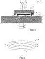
- Fig. 2 is a diagrammatic perspective view of a retaining ring having a bottom layer and a top layer formed from different material compositions.
- Fig. 3 is a diagrammatic perspective view of a retaining ring with a wear marker consisting of a colored ring disposed around the outer surface of the retaining ring.
- Fig. 4A is a diagrammatic perspective view of a retaining ring with a wear marker consisting of a groove disposed around the outer surface of the retaining ring.
- Fig. 4B is a diagrammatic cross-sectional side view of the retaining ring of Fig.
4A taken along the
line 4B-4B. - Fig. 5A is a diagrammatic perspective view of a retaining ring with a wear marker consisting of a plurality of vent holes extending from the outer surface to the inner surface of the retaining ring.
- Fig. 5B is a diagrammatic cross-sectional side view of the retaining ring of Fig.
5A taken along the
line 5B-5B. - Fig. 6A is a diagrammatic perspective view of a retaining ring having an internal annular ring of one material (or color) embedded in a retaining ring of a different material (or color).
- Fig. 6B is a diagrammatic cross-sectional side view of the retaining ring of Fig.
6A taken along the
line 6B-6B. - Fig. 7A is a diagrammatic bottom view of a grooved retaining ring with a wear marker consisting of a plurality of cylindrical wear markers disposed in the grooves of the retaining ring.
- Fig. 7B is a diagrammatic cross-sectional side view of the retaining ring of Fig.
7A taken along the
line 7B-7B. - Fig. 7C is a diagrammatic cross-sectional side view of an alternative grooved retaining ring with a wear marker consisting of a plurality of cylindrical wear markers disposed in the grooves of the retaining ring.
- Fig. 8 is a diagrammatic side view of a substrate polishing system that includes a substrate carrier head, a polishing pad mounted on a rotatable platen, and an optical detection system.
- Figs. 9A and 9B are graphs of the intensity of light detected by the optical detection system of Fig. 8 plotted against the distance across the width dimension of the substrate carrier head.
-
- Referring to Fig. 1, a
CMP polishing system 10 includes acarrier head 12 which is mounted to arotatable shaft 14, a polishing pad 16, and a rotatable platen 18 which is mounted to arotatable shaft 20.Carrier head 12 includes a retainingring 22 configured to hold asubstrate 24 in place oncarrier head 12. In operation,carrier head 12 holdssubstrate 24 against apolishing pad 26 of polishing pad 16, whilecarrier head 12 and rotatable platen 18 independently rotate relative to one another.Carrier head 12 also may be moved back-and-forth across polishingpad 26 over a linear or nonlinear polishing path. A reactive slurry solution may be deposited on polishingpad 26 to enhance the polishing process. - Retaining
ring 22 includes aninner surface 28 which is exposed to contact aperipheral edge 30 ofsubstrate 24, and abottom surface 32 which is exposed to contact polishingpad 26 whilesubstrate 24 is being polished. As mentioned above, after retainingring 22 has been exposed to the combined polishing action of polishingpad 26 and the reactive slurry solution for a period of time, retainingring 22 will have become sufficiently worn that it no longer is able to adequately perform the functions of holdingsubstrate 24 in place and improving the uniformity of the polishing process. At this point, retainingring 22 should be replaced. As described in detail below, retainingring 22 includes a wear marker that facilitates the determination of when retainingring 22 should be replaced. - Referring to Fig. 2, in one embodiment, retaining
ring 22 includes a bottom (or wear)layer 34 and a top (or support)layer 36. Awear marker 38 includes a visual indicator that is located at the outer surface of retainingring 22 and is exposed for visual inspection whilesubstrate 24 is being polished. In this embodiment, wearmarker 38 consists of a color change betweenbottom layer 34 andtop layer 36; these layers are formed from different material compositions.Bottom layer 22 is formed from a material, such as a fiber-reinforced TEFLON® matrix (e.g., a ZYMAXX® component available from DuPont) which may contact polishingpad 26 of polishing pad 16 without detrimental impact.Top layer 36 preferably also is formed from a material, such as a fiber-reinforced TEFLON® matrix, which may contact polishingpad 26 without a detrimental impact. The different colors ofbottom layer 34 andtop layer 36 may be achieved by embedding different fibers in the TEFLON® matrix. For example,layer 34 may appear black as a result of carbon fibers embedded in the matrix, andtop layer 36 may appear beige as a result of KEVLAR® fibers embedded in the matrix. - Other combinations of materials may be used to form top and
bottom layers bottom layer 34 andtop layer 36; the intermediate layers may be of different color to provide multiple warning indications to a CMP operator. Each layer may correspond to a preselected amount by which retainingring 22 has been worn away, and each layer may indicate a time when retainingring 22 should be replaced for a particular set of CMP process tolerance parameters. For example, an intermediate layer that is close tobottom layer 34 may indicate when retainingring 22 should be replaced when used in a CMP process that has relatively demanding tolerance parameters, whereas an intermediate layer that is closer totop layer 36 may indicate when retainingring 22 should be replaced when used in a CMP process that has less demanding tolerance parameters. - The thickness of bottom layer 34 (and therefore the location of wear marker 38) is selected to correspond to the amount by which bottom surface 32 of retaining
ring 22 may be worn away before the performance of retainingring 22 is significantly degraded. This amount may vary depending upon the nature of the polishing process (e.g., the rate at which retainingring 22 is worn away), polishing tolerances, and the particular impact of the gradual thinning of retainingring 22 on the polishing process. - In operation, a CMP operator may visually inspect the outer surface of retaining
ring 22 before, during or after a CMP process, and when the color ofbottom layer 34 is no longer visible, the operator may replace retainingring 22. Alternatively, when used in substrate polishing system 87 (described below in connection with Fig. 8), the polishing system automatically may detect when retainingring 22 should be replaced. For example, if the reflectivity ofbottom layer 34 is different from the reflectivity oftop layer 36, the polishing system would detect whenbottom layer 34 has been worn away based upon a change in detected signal intensity at the location of retainingring 22. To achieve a difference in reflectivity, for example,bottom layer 34 may be formed from a thermoplastic, such as PPS® mechanical plastic (available from Interstate Plastic, Inc. of Sacramento, California, U.S.A.) or a polyurethane composition, andtop layer 36 may be formed from a metal (e.g.. aluminum or stainless steel). Alternatively,bottom layer 34 andtop layer 36 may be formed from different color materials. - As shown in Fig. 3, in another embodiment, a
wear marker 40 consists of a ring of a substance that defines a plane that is substantially parallel tobottom surface 32 and has a different color than the substance forming retainingring 22. For example, retainingring 22 may be formed from a light-colored polyurethane material and wearmarker 40 may be formed from a dark colorant (e.g., a paint or a dye) applied (or injected into) the outer surface of retainingring 22. In operation, a CMP operator may visually inspect the outer surface of retainingring 22 before, during or after a CMP process, and whenwear marker 40 is no longer visible, the operator may replace retainingring 22. - Referring to Figs. 4A and 4B, in another embodiment, a
wear marker 42 consists of anannular groove 44 that is formed in the outer surface of retainingring 22 and defines a plane that is substantially parallel tobottom surface 32. The location of annular groove 44 (and therefore the location of wear marker 42) is selected to correspond to the amount by which bottom surface 32 of retainingring 22 may be worn away before the performance of retainingring 22 is significantly degraded. Retainingring 22 may be replaced when a CMP operator visually observes thatbottom surface 32 of retainingring 22 has been worn away up togroove 44. - As shown in Figs. 5A and 5B, in another embodiment, a wear marker 46 may consist of one or more angled vent holes 48, 50, 52 and 54, that extend from the outer surface of retaining
ring 22 toinner surface 28. Vent holes 48-54 preferably extend in a linear direction from the outer surface of retainingring 22 toinner surface 28 and are oriented at an acute angle relative tobottom surface 32, as shown. The locations where vent holes 48-52 appear in the outer surface of retaining ring 22 (and therefore the location of wear marker 46) is selected to correspond to the amount by which bottom surface 32 of retainingring 22 may be worn away before the performance of retainingring 22 is significantly degraded. Retainingring 22 may be replaced when a CMP operator visually observes thatbottom surface 32 of retainingring 22 has been worn away up to the locations where vent holes 48-54 are formed in the outer surface of retainingring 22. Because the vent holes are angled, the polishing pad is exposed to only a portion of the groove that is formed afterbottom surface 32 of retainingring 22 has been worn away up to the locations where vent holes 48-54 are formed in the outer surface of retainingring 22. - Referring to Figs. 6A and 6B, another retaining ring embodiment includes a
wear marker 56 that is exposed for detection atbottom surface 32 of retainingring 22 afterbottom surface 32 has been worn away by a preselected amount. In this embodiment, wearmarker 56 is formed from aninternal ring 58 embedded within retainingring 22.Internal ring 58 is formed from material that is different from the material composition of retainingring 22. Retainingring 22 may formed from a material, such as a fiber-reinforced TEFLON® matrix (e.g., a ZYMAXX® component available from DuPont) which may contact polishingpad 26 of polishing pad 16 without detrimental impact.Internal ring 58 preferably also is formed from a material, such as a fiber-reinforced TEFLON® matrix, which may contact polishingpad 26 without a detrimental impact. The different detection characteristics ofinternal ring 58 and retainingring 22 may be achieved by embedding different fibers in the TEFLON® matrices. For example,internal ring 58 may appear black as a result of carbon fibers embedded in the matrix, and retainingring 22 may appear beige as a result of KEVLAR® fibers embedded in the matrix. In an alternative embodiment, retainingring 22 may be formed from a polymeric material (e.g., polyurethane) andinternal ring 58 may be formed from a metal (e.g., aluminum or stainless steel). -
Internal ring 58 extends into retaining ring 22 adepth 60 that is selected to correspond to the amount by which bottom surface 32 of retainingring 22 may be worn away before the performance of retainingring 22 is significantly degraded. As mentioned above, this amount may vary depending upon the nature of the polishing process (e.g., the polishing rate of retaining ring 22), polishing tolerances, and the particular impact of the gradual thinning of retainingring 22 on the polishing process. - In operation, a CMP operator may visually inspect
bottom surface 32 of retainingring 22 before or after a CMP process, and when the bottom surface ofinternal ring 58 appears, the operator may replace retainingring 22. Alternatively, when used in substrate polishing system 87 (described below in connection with Fig. 8), the polishing system automatically may detect when retainingring 22 should be replaced. For example, if the reflectivity ofinternal ring 58 is different from the reflectivity of retaining ring 22 (e.g., wheninternal ring 58 is formed from a metal and retainingring 22 is formed from a polymeric material), the polishing system would detect whenbottom surface 32 has been sufficiently worn away based upon a change in detected signal intensity at the location of retainingring 22. - In an alternative embodiment,
internal ring 58 may be replaced by one or more spaced-apart wear marker plugs (or pins) that are formed from a material that is different from the material composition of retainingring 22. These wear marker plugs may be distributed along an annular path corresponding to the location ofinternal ring 58 and may extend into retainingring 22 the same depth asinternal ring 58. - Referring to Figs. 7A and 7B, in another embodiment, retaining
ring 22 includes a plurality ofangled grooves characteristic depth 70, and a wear marker consisting of a plurality of spaced-apart wear marker plugs (or pins) 72, 74, 76 and 78 that are formed from a material that is different from the material composition of retainingring 22. Plugs 72-78 are exposed for detection (e.g., by automatic optical detection) after the depth of the groove has been reduced sufficiently by wearing -- this depth may be less thancharacteristic depth 70. Plugs 72-78 are formed from material that is different from the material composition of retainingring 22. Retainingring 22 may formed from a material, such as a fiber-reinforced TEFLON® matrix (e.g., a ZYMAXX® component available from DuPont), which may contact polishingpad 26 of polishing pad 16 without detrimental impact. Plugs 72-78 preferably also are formed from a material, such as a fiber-reinforced TEFLON® matrix, which may contact polishingpad 26 without a detrimental impact. The different detection characteristics of plugs 72-78 and retainingring 22 may be achieved by embedding different fibers in the TEFLON® matrices. For example, plugs 72-78 may appear black as a result of carbon fibers embedded in the matrix, and retainingring 22 may appear biege as a result of KEVLAR® fibers embedded in the matrix. In an alternative embodiment, retainingring 22 may be formed from a polymeric material (e.g., polyurethane) and plugs 72-78 may be formed from a metal (e.g., aluminum or stainless steel). - In an alternative embodiment, wear marker plugs 72-78 may be replaced by layers (or coatings) of a material that is of a different material composition than retaining
ring 22 and is disposed along the bottom surface of grooves 62-68. Suitable layers include layers that produce an initial optical response at a time beforebottom surface 32 has been worn away that is different from the optical response produced when retainingring 22 has been sufficiently worn that it should be replaced. For example, these layers may be formed from a reflective material (e.g., aluminum or stainless steel). - In operation, when used in the substrate polishing system described below in connection with Fig. 8, the polishing system automatically may detect when retaining
ring 22 should be replaced. For example, if the optical characteristics of plugs 72-78 are different from the optical characteristics of retaining ring 22 (e.g., when plugs 72-78 are formed from a metal and retainingring 22 is formed from a polymeric material), the polishing system would detect whenbottom surface 32 has been sufficiently worn away based upon a change in detected optical signal intensity at the location of plugs 72-78. Specifically, as the bottom surface of retainingring 22 is worn away, plugs 72-78 move closer towindow 90, resulting in a change in the detected optical signal intensity. - As shown in Fig. 7C, plugs 72-78 may be sunk into
respective recesses polishing pad 26 of polishing pad 16, or both. - Referring to Fig. 8, in one embodiment, platen 18 of
substrate polishing system 10 includes alight passage 88 and polishing pad 16 includes awindow 90 formed from a material (e.g., polyurethane) that is at least semi-transparent (substantially transmissive) with respect to the light produced by amonitoring system 92. In operation,monitoring system 92 produces alaser beam 94, e.g., at least a portion of which passes throughlight passage 88 andwindow 90. A portion ofbeam 94 is partially reflected from one or more layers ofsubstrate 24 and retainingring 22 to produce abeam 96 which has an intensity that varies as layers are removed fromsubstrate 24 and varies as the optical characteristics (e.g., reflectivity) of retainingring 22 change over time. For example, if the surface layer ofsubstrate 24 is partially reflective and partially transmissive,beam 96 will be formed from at least two beams reflecting from different surfaces and the intensity ofbeam 96 will vary depending on whether the constituent beams interfere constructively or destructively, a characteristic which is primarily a function of the thickness of the surface layer ofsubstrate 24. If the surface layer is substantially reflective, the intensity ofbeam 96 will be significantly reduced when the surface layer has been polished away.Monitoring system 92 monitors the variation in the intensity ofbeam 96 during a polishing process to determine the amount of material that has been removed from the surface ofsubstrate 24, to determine the end point of the polishing process, and to determine when retainingring 22 should be replaced. The operation ofmonitoring system 92 is coordinated with the movement ofcarrier head 12 to enablemonitoring system 92 to periodically probesubstrate 24. In particular,monitoring system 92 is configured to trigger the laser whensubstrate 24 is positioned overwindow 90; alternatively,monitoring system 92 may be configured to open a shutter over the detector whensubstrate 24 is positioned overwindow 90. - Referring to Figs. 9A and 9B,
monitoring system 92 automatically may determine when to replace retainingring 22 as follows. At an initial time T0 (before retainingring 22 should be replaced),monitoring system 92 detects the intensity ofbeam 96 across the width dimension ofcarrier head 12. The resultingintensity distribution 100 is characterized by a relatively low (or high) intensity at thelocations ring 22 and by a relatively high (or low) intensity at thelocations 106 corresponding tosubstrate 24. At a later time T1 (after retainingring 22 has been sufficiently worn away that it should be replaced, usually after 1,500-4,000 substrates have been polished), the resultingintensity distribution 108 detected by monitoringsystem 92 is characterized by a higher +|ΔI| (or lower -|ΔI|) detected intensity at the locations corresponding to retainingring 22 relative to the intensity detected at time T0. Once the detected intensity (110, 112) of the light received from retainingring 22 exceeds (or is lower than) the initial intensity (102, 104) by more than a selected threshold (i.e., |ΔI| > IThreshold),monitoring system 92 generates a warning signal indicating that retainingring 22 should be replaced. It should be noted that the threshold (IThreshold) selected will depend upon the characteristics of retainingring 22, the type and composition of wear marker used, and the characteristics ofmonitoring system 92. Also, it should be noted that the detected intensity of light received from retainingring 22 may exceed (or be lower than) the detected intensity of light received fromsubstrate 24 depending upon the optical characteristics ofsubstrate 24, retainingring 22 and the wear marker used. - Other embodiments are within the scope of the claims. The invention may be implemented with other substrate polishing designs. For example, rotatable platen 18 and polishing pad 16 may be implemented with a different rotating polishing system design, or may be replaced by a linear drive mechanism and a linear polishing pad.
-
Monitoring system 92 may be configured to directbeam 94 at the outer surface of retainingring 22. This configuration may be used in combination with the embodiments of Figs. 2-5B to detect changes in the optical characteristics of the outer surface of retainingring 22 asbottom surface 32 is being worn away.
Claims (21)
- A retaining ring, comprising:an inner surface exposed to contact, in use, a peripheral edge of a substrate to be polished against a polishing surface;a bottom surface exposed to contact, in use, the polishing surface while the substrate is being polished; anda wear marker indicative of a preselected amount of wear of the bottom surface.
- The retaining ring of claim 1, further comprising an outer surface, wherein the wear marker comprises a visual indicator that is located at the outer surface and is exposed for visual inspection while the substrate is being polished.
- The retaining ring of claim 2, wherein the visual indicator comprises a colour change.
- The retaining ring of claim 3, wherein the colour change results from a change in material composition between the bottom surface and the location of the visual indicator.
- The retaining ring of claim 3, wherein the colour change results from a colourant applied to the outer surface.
- The retaining ring of claim 2, wherein the wear marker comprises a change in a structural feature of the outer surface.
- The retaining ring of claim 6, wherein the structural feature change comprises a hole extending from the outer surface to the inner surface.
- The retaining ring of claim 6, wherein the structural feature change comprises a continuous groove that defines a plane that is substantially parallel to the bottom surface.
- The retaining ring of claim 1, further comprising an outer surface, wherein the wear marker is exposed for detection at the bottom surface after the bottom surface has been worn away by a preselected amount.
- The retaining ring of claim 9, wherein the wear marker and the bottom surface are formed from different material compositions.
- The retaining ring of claim 10, wherein the material compositions of the wear marker and the bottom surface have different reflectivity characteristics.
- The retaining ring of claim 11, wherein the wear marker is formed from a metal and the bottom surface is formed from a polymeric material.
- The retaining ring of any one of claims 9 to 12, wherein the bottom surface comprises a groove having a characteristic depth and the wear marker is exposed for detection after the depth of the groove has been reduced sufficiently by wearing.
- The retaining ring of claim 13, wherein the wear marker comprises a metallic surface disposed in the groove.
- The retaining ring of claim 13 or claim 14, wherein the wear marker comprises an annular ring.
- The retaining ring of claim 13, wherein the wear marker comprises one or more spaced-apart wear mark plugs.
- A substrate polishing apparatus, comprising:a carrier head configured to hold a substrate against a polishing surface; anda retaining ring according to any one of the preceding claims.
- The apparatus of claim 17, further comprising an optical detection system configured to detect the wear and to generate a warning signal upon detection of the wear marker.
- A substrate polishing method, comprising:polishing one or more substrates against a polishing surface with a retaining ring having an inner surface exposed to contact a peripheral edge of the substrate, a bottom surface exposed to contact the polishing surface while the substrate is being polished, and a wear marker indicative of a preselected amount of wear of the bottom surface; andreplacing at least a portion of the retaining ring when the bottom surface has been worn away by the preselected amount indicated by the wear marker.
- A substrate polishing method, comprising:polishing one or more substrates against a polishing surface with a substrate carrier that includes a substrate retaining ring with a wear marker indicative of a preselected amount of wear of the retaining ring; andgenerating a warning signal upon detection of the wear marker.
- The method of claim 20, further comprising optically detecting the wear marker.
Applications Claiming Priority (2)
| Application Number | Priority Date | Filing Date | Title |
|---|---|---|---|
| US345429 | 1999-07-01 | ||
| US09/345,429 US6390908B1 (en) | 1999-07-01 | 1999-07-01 | Determining when to replace a retaining ring used in substrate polishing operations |
Publications (2)
| Publication Number | Publication Date |
|---|---|
| EP1065030A2 true EP1065030A2 (en) | 2001-01-03 |
| EP1065030A3 EP1065030A3 (en) | 2003-06-11 |
Family
ID=23355008
Family Applications (1)
| Application Number | Title | Priority Date | Filing Date |
|---|---|---|---|
| EP00304382A Withdrawn EP1065030A3 (en) | 1999-07-01 | 2000-05-24 | Determining when to replace a retaining ring used in substrate polishing operations |
Country Status (4)
| Country | Link |
|---|---|
| US (1) | US6390908B1 (en) |
| EP (1) | EP1065030A3 (en) |
| JP (1) | JP2001025962A (en) |
| TW (1) | TW466151B (en) |
Cited By (7)
| Publication number | Priority date | Publication date | Assignee | Title |
|---|---|---|---|---|
| WO2003015147A1 (en) * | 2001-08-03 | 2003-02-20 | Clariant International Ltd. | Wafer holding ring for chemical and mechanical polisher |
| WO2004033153A2 (en) * | 2002-10-02 | 2004-04-22 | Ensinger Kunststofftechnologie Gbr | Retaining ring for holding semiconductor wafers in a chemical-mechanical polishing device |
| DE102004017789A1 (en) * | 2004-04-02 | 2005-10-20 | Ensinger Kunststofftechnologie | Retaining ring for holding semiconductor wafers in a chemical mechanical polishing apparatus |
| EP2418677A3 (en) * | 2004-11-01 | 2014-04-02 | Ebara Corporation | Polishing apparatus |
| CN105345652A (en) * | 2015-10-14 | 2016-02-24 | 上海华力微电子有限公司 | Fixing ring with abrasion remaining thickness capable of being detected in real time |
| WO2017065951A1 (en) | 2015-10-16 | 2017-04-20 | Applied Materials, Inc. | Corrosion resistant retaining rings |
| EP2651601A4 (en) * | 2010-12-16 | 2018-03-14 | Saint-Gobain Abrasives, Inc. | A slot wear indicator for a grinding tool |
Families Citing this family (40)
| Publication number | Priority date | Publication date | Assignee | Title |
|---|---|---|---|---|
| WO2003011517A1 (en) * | 2001-08-01 | 2003-02-13 | Entegris, Inc. | Wafer carrier wear indicator |
| TW545580U (en) * | 2002-06-07 | 2003-08-01 | Nanya Technology Corp | CMP device of measuring apparatus with a notched size for measuring the guide ring of wafer edge |
| DE10247179A1 (en) * | 2002-10-02 | 2004-04-15 | Ensinger Kunststofftechnologie Gbr | Retaining ring for holding semiconductor wafers in a chemical mechanical polishing device |
| US20040259485A1 (en) * | 2002-10-02 | 2004-12-23 | Ensinger Kunstsofftechnoligie Gbr | Retaining ring for holding semiconductor wafers in a chemical mechanical polishing apparatus |
| US20040261945A1 (en) * | 2002-10-02 | 2004-12-30 | Ensinger Kunststofftechnoligie Gbr | Retaining ring for holding semiconductor wafers in a chemical mechanical polishing apparatus |
| TWI238754B (en) * | 2002-11-07 | 2005-09-01 | Ebara Tech Inc | Vertically adjustable chemical mechanical polishing head having a pivot mechanism and method for use thereof |
| DE10311830A1 (en) * | 2003-03-14 | 2004-09-23 | Ensinger Kunststofftechnologie Gbr | Spacer profile between glass panes in a double glazing structure has an organic and/or inorganic bonding agent matrix containing particles to adsorb water vapor and keep the space dry |
| US6964597B2 (en) * | 2003-06-27 | 2005-11-15 | Khuu's Inc. | Retaining ring with trigger for chemical mechanical polishing apparatus |
| US6939202B2 (en) * | 2003-08-13 | 2005-09-06 | Intel Corporation | Substrate retainer wear detection method and apparatus |
| US6895631B1 (en) | 2004-09-08 | 2005-05-24 | Dedication To Detail, Inc. | Buffing pad wear indicator |
| JP4817687B2 (en) * | 2005-03-18 | 2011-11-16 | 株式会社荏原製作所 | Polishing equipment |
| AU2007200069A1 (en) * | 2006-01-06 | 2007-07-26 | Craig Edward Harder | Magnetic wear device |
| JP4814677B2 (en) * | 2006-03-31 | 2011-11-16 | 株式会社荏原製作所 | Substrate holding device and polishing device |
| US20080271384A1 (en) * | 2006-09-22 | 2008-11-06 | Saint-Gobain Ceramics & Plastics, Inc. | Conditioning tools and techniques for chemical mechanical planarization |
| JP5267918B2 (en) * | 2008-07-15 | 2013-08-21 | 株式会社ニコン | Holding device and polishing device |
| CN103962943A (en) * | 2009-03-24 | 2014-08-06 | 圣戈班磨料磨具有限公司 | Abrasive tool for use as a chemical mechanical planarization pad conditioner |
| US8905823B2 (en) | 2009-06-02 | 2014-12-09 | Saint-Gobain Abrasives, Inc. | Corrosion-resistant CMP conditioning tools and methods for making and using same |
| SG178605A1 (en) | 2009-09-01 | 2012-04-27 | Saint Gobain Abrasives Inc | Chemical mechanical polishing conditioner |
| US20120021671A1 (en) * | 2010-07-26 | 2012-01-26 | Applied Materials, Inc. | Real-time monitoring of retaining ring thickness and lifetime |
| KR101143173B1 (en) * | 2010-09-13 | 2012-05-08 | 오세열 | Polishing pad |
| US8535115B2 (en) * | 2011-01-28 | 2013-09-17 | Applied Materials, Inc. | Gathering spectra from multiple optical heads |
| KR101902049B1 (en) | 2012-01-25 | 2018-09-27 | 어플라이드 머티어리얼스, 인코포레이티드 | Retaining ring monitoring and control of pressure |
| US9067295B2 (en) | 2012-07-25 | 2015-06-30 | Applied Materials, Inc. | Monitoring retaining ring thickness and pressure control |
| KR101415983B1 (en) * | 2012-12-24 | 2014-07-08 | 주식회사 케이씨텍 | Wafer cleaner |
| PT2792655E (en) * | 2013-04-18 | 2015-08-24 | Refractory Intellectual Prop | Wear indicator in a composite system of refractory ceramic bricks |
| US9242338B2 (en) * | 2013-10-22 | 2016-01-26 | Globalfoundries Singapore Pte. Ltd. | CMP head structure |
| US9242341B2 (en) | 2013-10-22 | 2016-01-26 | Globalfoundries Singapore Pte. Ltd. | CMP head structure |
| US9597771B2 (en) * | 2013-12-19 | 2017-03-21 | Taiwan Semiconductor Manufacturing Co., Ltd. | Carrier head having retainer ring, polishing system including the carrier head and method of using the polishing system |
| JP6344950B2 (en) * | 2014-03-31 | 2018-06-20 | 株式会社荏原製作所 | Polishing apparatus and polishing method |
| WO2016100665A1 (en) | 2014-12-19 | 2016-06-23 | Stryker Corporation | Composite material with failure detection properties |
| KR102564376B1 (en) | 2016-09-15 | 2023-08-04 | 어플라이드 머티어리얼스, 인코포레이티드 | Chemical mechanical polishing smart ring |
| CN107717639A (en) * | 2017-11-09 | 2018-02-23 | 宁波江丰电子材料股份有限公司 | Control the method for retaining ring flatness and retaining ring, the semiconductor fabrication system of production |
| KR20200120960A (en) * | 2018-03-13 | 2020-10-22 | 어플라이드 머티어리얼스, 인코포레이티드 | Monitoring of consumable parts in chemical mechanical polishers |
| CN109854710A (en) * | 2019-01-09 | 2019-06-07 | 上海市轴承技术研究所 | The wear-resisting retaining ring of tooth form |
| JP2020179478A (en) * | 2019-04-26 | 2020-11-05 | 株式会社ディスコ | Chuck table |
| CN110103143B (en) * | 2019-05-10 | 2020-04-07 | 北方民族大学 | Stainless steel rolling ring finish machining equipment for radial pressure gauge |
| US11254112B2 (en) | 2019-07-31 | 2022-02-22 | Stryker Corporation | Cover with wear detection properties |
| CN114505782B (en) * | 2020-11-17 | 2023-08-04 | 长鑫存储技术有限公司 | Fixing device and detection system |
| US20230003639A1 (en) * | 2021-07-01 | 2023-01-05 | Sherrill, Inc. | Rope Ring with Wear Indicator |
| CN114406896A (en) * | 2022-01-25 | 2022-04-29 | 上海江丰平芯电子科技有限公司 | Retaining ring capable of rapidly detecting service life and use method thereof |
Citations (2)
| Publication number | Priority date | Publication date | Assignee | Title |
|---|---|---|---|---|
| US5695392A (en) * | 1995-08-09 | 1997-12-09 | Speedfam Corporation | Polishing device with improved handling of fluid polishing media |
| US5913713A (en) * | 1997-07-31 | 1999-06-22 | International Business Machines Corporation | CMP polishing pad backside modifications for advantageous polishing results |
Family Cites Families (6)
| Publication number | Priority date | Publication date | Assignee | Title |
|---|---|---|---|---|
| JPH06304872A (en) * | 1993-04-22 | 1994-11-01 | Ricoh Co Ltd | Grinding wheel |
| JP3804117B2 (en) * | 1996-09-20 | 2006-08-02 | ソニー株式会社 | Substrate polishing method and polishing apparatus used for the same |
| JPH10217109A (en) * | 1997-02-04 | 1998-08-18 | Nippon Steel Corp | Work holding device of polishing device |
| US5944593A (en) * | 1997-09-01 | 1999-08-31 | United Microelectronics Corp. | Retainer ring for polishing head of chemical-mechanical polish machines |
| US5967885A (en) * | 1997-12-01 | 1999-10-19 | Lucent Technologies Inc. | Method of manufacturing an integrated circuit using chemical mechanical polishing |
| US5947053A (en) * | 1998-01-09 | 1999-09-07 | International Business Machines Corporation | Wear-through detector for multilayered parts and methods of using same |
-
1999
- 1999-07-01 US US09/345,429 patent/US6390908B1/en not_active Expired - Lifetime
-
2000
- 2000-02-15 JP JP2000036871A patent/JP2001025962A/en active Pending
- 2000-02-18 TW TW089102869A patent/TW466151B/en not_active IP Right Cessation
- 2000-05-24 EP EP00304382A patent/EP1065030A3/en not_active Withdrawn
Patent Citations (2)
| Publication number | Priority date | Publication date | Assignee | Title |
|---|---|---|---|---|
| US5695392A (en) * | 1995-08-09 | 1997-12-09 | Speedfam Corporation | Polishing device with improved handling of fluid polishing media |
| US5913713A (en) * | 1997-07-31 | 1999-06-22 | International Business Machines Corporation | CMP polishing pad backside modifications for advantageous polishing results |
Cited By (19)
| Publication number | Priority date | Publication date | Assignee | Title |
|---|---|---|---|---|
| WO2003015147A1 (en) * | 2001-08-03 | 2003-02-20 | Clariant International Ltd. | Wafer holding ring for chemical and mechanical polisher |
| US6896602B2 (en) | 2001-08-03 | 2005-05-24 | Clariant Finance (Bvi) Limited | Wafer holding ring for chemical and mechanical polisher |
| CN100341118C (en) * | 2001-08-03 | 2007-10-03 | Az电子材料(日本)株式会社 | Wafer holding ring for chemical and mechanical polisher |
| KR100847428B1 (en) * | 2001-08-03 | 2008-07-21 | 에이제토 엘렉토로닉 마티리알즈 가부시키가이샤 | Wafer holding ring for chemical and mechanical polisher |
| WO2004033153A2 (en) * | 2002-10-02 | 2004-04-22 | Ensinger Kunststofftechnologie Gbr | Retaining ring for holding semiconductor wafers in a chemical-mechanical polishing device |
| WO2004033153A3 (en) * | 2002-10-02 | 2004-07-01 | Ensinger Kunststofftechnologie | Retaining ring for holding semiconductor wafers in a chemical-mechanical polishing device |
| DE102004017789A1 (en) * | 2004-04-02 | 2005-10-20 | Ensinger Kunststofftechnologie | Retaining ring for holding semiconductor wafers in a chemical mechanical polishing apparatus |
| US8845396B2 (en) | 2004-11-01 | 2014-09-30 | Ebara Corporation | Polishing apparatus |
| EP2418677A3 (en) * | 2004-11-01 | 2014-04-02 | Ebara Corporation | Polishing apparatus |
| CN105904335A (en) * | 2004-11-01 | 2016-08-31 | 株式会社荏原制作所 | Polishing apparatus |
| US9724797B2 (en) | 2004-11-01 | 2017-08-08 | Ebara Corporation | Polishing apparatus |
| US10040166B2 (en) | 2004-11-01 | 2018-08-07 | Ebara Corporation | Polishing apparatus |
| US10293455B2 (en) | 2004-11-01 | 2019-05-21 | Ebara Corporation | Polishing apparatus |
| US11224956B2 (en) | 2004-11-01 | 2022-01-18 | Ebara Corporation | Polishing apparatus |
| EP2651601A4 (en) * | 2010-12-16 | 2018-03-14 | Saint-Gobain Abrasives, Inc. | A slot wear indicator for a grinding tool |
| CN105345652A (en) * | 2015-10-14 | 2016-02-24 | 上海华力微电子有限公司 | Fixing ring with abrasion remaining thickness capable of being detected in real time |
| WO2017065951A1 (en) | 2015-10-16 | 2017-04-20 | Applied Materials, Inc. | Corrosion resistant retaining rings |
| KR20180058839A (en) * | 2015-10-16 | 2018-06-01 | 어플라이드 머티어리얼스, 인코포레이티드 | Corrosion resistant retaining ring |
| EP3362222A4 (en) * | 2015-10-16 | 2019-05-29 | Applied Materials, Inc. | Corrosion resistant retaining rings |
Also Published As
| Publication number | Publication date |
|---|---|
| JP2001025962A (en) | 2001-01-30 |
| US6390908B1 (en) | 2002-05-21 |
| EP1065030A3 (en) | 2003-06-11 |
| TW466151B (en) | 2001-12-01 |
Similar Documents
| Publication | Publication Date | Title |
|---|---|---|
| US6390908B1 (en) | Determining when to replace a retaining ring used in substrate polishing operations | |
| KR20040039201A (en) | Apparatus and method for measuring tool degradation | |
| US6929530B1 (en) | Apparatus for in-situ optical endpointing on web-format planarizing machines in mechanical or chemical-mechanical planarization of microelectronic-device substrate assemblies and methods for making and using same | |
| EP0881040B1 (en) | Method and apparatus for in-situ monitoring of thickness using a multi-wavelength spectrometer during chemical-mechanical polishing | |
| US5934974A (en) | In-situ monitoring of polishing pad wear | |
| AU2009212871B2 (en) | Method for determining the wear state | |
| US7008295B2 (en) | Substrate monitoring during chemical mechanical polishing | |
| US6821794B2 (en) | Flexible snapshot in endpoint detection | |
| US20010044257A1 (en) | Methods for predicting polishing parameters of polishing pads, and methods and machines for planarizing microelectronic substrate assemblies in mechanical or chemical-mechanical planarization | |
| KR20010022689A (en) | Method and apparatus for endpoint detection for chemical mechanical polishing | |
| KR19980018668A (en) | Method for forming transparent window in polishing pad for chemical mechanical polishing device | |
| US7341502B2 (en) | Methods and systems for planarizing workpieces, e.g., microelectronic workpieces | |
| CN111300268B (en) | Tool device and method for measuring the state of a machining tool | |
| JP2008508107A (en) | System and method for detecting the orientation of an abrasive article | |
| US20190232459A1 (en) | Polishing pad with multipurpose composite window | |
| US20020182986A1 (en) | Polishing pad with wear indicator for profile monitoring and controlling and method and apparatus for polishing using said pad | |
| AU2014100795B4 (en) | A method of determining the wear state | |
| WO2009084944A1 (en) | Method and device for inspecting a ring component produced in or for a drive belt manufacturing process | |
| KR20190056334A (en) | Polishing pad with pad wear indicator | |
| WO2020219076A1 (en) | Evaluating surfaces | |
| JP2005340718A (en) | Polishing pad and chemical mechanical polishing device | |
| US7795555B2 (en) | Process for determining whether used friction elements may be returned to service | |
| US20030181136A1 (en) | CMP pad platen with viewport | |
| KR20050051094A (en) | Polishing pad and apparatus for chemical and mechanical polishing semiconductor substrate having the same | |
| KR20050103358A (en) | Platen of chemical and mechanical polishing apparatus |
Legal Events
| Date | Code | Title | Description |
|---|---|---|---|
| PUAI | Public reference made under article 153(3) epc to a published international application that has entered the european phase |
Free format text: ORIGINAL CODE: 0009012 |
|
| AK | Designated contracting states |
Kind code of ref document: A2 Designated state(s): AT BE CH CY DE DK ES FI FR GB GR IE IT LI LU MC NL PT SE |
|
| AX | Request for extension of the european patent |
Free format text: AL;LT;LV;MK;RO;SI |
|
| PUAL | Search report despatched |
Free format text: ORIGINAL CODE: 0009013 |
|
| AK | Designated contracting states |
Designated state(s): AT BE CH CY DE DK ES FI FR GB GR IE IT LI LU MC NL PT SE |
|
| AX | Request for extension of the european patent |
Extension state: AL LT LV MK RO SI |
|
| RIC1 | Information provided on ipc code assigned before grant |
Ipc: 7B 24B 49/12 B Ipc: 7B 24B 55/00 B Ipc: 7B 24B 41/06 B Ipc: 7B 24B 37/04 A |
|
| AKX | Designation fees paid | ||
| REG | Reference to a national code |
Ref country code: DE Ref legal event code: 8566 |
|
| STAA | Information on the status of an ep patent application or granted ep patent |
Free format text: STATUS: THE APPLICATION IS DEEMED TO BE WITHDRAWN |
|
| 18D | Application deemed to be withdrawn |
Effective date: 20031212 |