EP1064514B1 - Striking pin control mechanism - Google Patents
Striking pin control mechanism Download PDFInfo
- Publication number
- EP1064514B1 EP1064514B1 EP99908800A EP99908800A EP1064514B1 EP 1064514 B1 EP1064514 B1 EP 1064514B1 EP 99908800 A EP99908800 A EP 99908800A EP 99908800 A EP99908800 A EP 99908800A EP 1064514 B1 EP1064514 B1 EP 1064514B1
- Authority
- EP
- European Patent Office
- Prior art keywords
- firing pin
- slide
- spring
- housing
- cartridge
- Prior art date
- Legal status (The legal status is an assumption and is not a legal conclusion. Google has not performed a legal analysis and makes no representation as to the accuracy of the status listed.)
- Expired - Lifetime
Links
Images


Classifications
-
- F—MECHANICAL ENGINEERING; LIGHTING; HEATING; WEAPONS; BLASTING
- F41—WEAPONS
- F41A—FUNCTIONAL FEATURES OR DETAILS COMMON TO BOTH SMALLARMS AND ORDNANCE, e.g. CANNONS; MOUNTINGS FOR SMALLARMS OR ORDNANCE
- F41A17/00—Safety arrangements, e.g. safeties
- F41A17/64—Firing-pin safeties, i.e. means for preventing movement of slidably- mounted strikers
- F41A17/66—Firing-pin safeties, i.e. means for preventing movement of slidably- mounted strikers automatically operated, i.e. operated by breech opening or closing movement
Definitions
- the invention relates to a handgun with a Lock moving into one for igniting one Cartridge fitted end position is movable, one in Closure along a trajectory movably mounted firing pin with a striker pin spring (1) loading it backwards and one Demolition device by a trigger device is triggered and is set up to ignite a Cartridge on the side facing away from this firing pin end réelle transformer and thereby the firing pin in his To spend ignition position.
- a weapon is out No. 1,363,040.
- top o. The like. go out from the horizontal position of use of the weapon when Shot, wherein the weft direction points to "front” (in the Drawing to the left).
- a cock can also be provided a hammer, the not, as a cock is pivotable about a fixed axis, but e.g. guided in a straight-line movement path and is movable under load a striker.
- a cock is pivotable about a fixed axis, but e.g. guided in a straight-line movement path and is movable under load a striker.
- the trigger means To prevent the tap from knocking off already, open the firing pin end hits and the ignition of the cartridge caused before the shutter is completely closed is in the trigger means a breaker mechanism provided that the triggering connection between the Deduction and the cock only then produces or with continuous fire the cock only triggers when the shutter is full closed is. At the same time, this breaker mechanism becomes controlled by the position of the shutter, so that In principle, the delivery of a shot only possible is when the shutter is completely closed.
- the invention is the Task is to provide an additional device, the forcible triggering a shot only then allows if the shutter the cartridge sufficiently far introduced into the chamber.
- Ansprüchs 1 It is the one independent of the trigger device, additional Device for preventing the by the Demolition device or the cock triggered movement of the Firing pin provided in its firing position.
- This facility is set up to handle this movement Only allow firing pin in its firing position, if the shutter has reached its end position and thus the Cartridge so far introduced into the chamber, that this is sufficiently supported.
- the invention therefore provides for a separate Device whose purpose is to use the firing pin for so long to prevent reaching its ignition position until the shutter reached its final position until the security measure. in this connection it is clear to those skilled in the art that the end position no point along the movement distance of the shutter is, but a Tolerance field, which is very narrow.
- The, additional facility could be about consist of a rocker arm, the pivoting in the closure is stored by a spring with his one leg in locking engagement with the closure is depressible and with its other end on the front face or one Side surface of the closure over this protrudes.
- this protruding leg in the Movement path of this protruding leg is on the barrel or on the housing a stop surface provided against the when closing the shutter this protruding Thigh starts while doing the other leg of the Rocker arm out of engagement with the firing pin lifts.
- the Arrangement of the abutment surface is such that the Firing pin is released only when the shutter has reached the tolerance field of its final position.
- the firing pin then, if ignition should be prevented from the range of motion to spend the tee-off facility.
- the firing point set up for ignition from a position opposite the primer of the cartridge remove but then could be a knock off the Demolition device may damage the firing pin to lead.
- the firing pin could be tilted so that it with its rear end transverse to its direction of movement is offset, as known from certain backups ago is. According to the invention but the firing pin is such Measure moved forward, that he reliably still behind its firing position lies, but so far in the lock dips in that his rear end before contact with the Rooster or a hammer by training of the Closure, preferably the rear end face of the Closure, is protected.
- This embodiment is especially with a weapon to prefer, where the cock is completely within the housing, so that not the There is a risk that a foreign body between cock and Firing pin device and then still for an ignition could provide.
- the firing pin could in the described security situation by the closing spring acting on the closure be spent.
- the invention is one Provided counter spring, extending between shutter and Striker supported, but this only up in his Can press security.
- the spring force of the opposing spring This is higher than that of the firing pin spring used.
- the Counter spring In the forward movement of the shutter occurs just before it reaches its final position, the Counter spring with a stationary housing education, about a housing projection o. The like., Engages and breaks thereby their action on the firing pin off, the now as far as moved back by the action of his firing pin spring can be that the cock then unhindered on the Can strike the firing pin.
- the stationary housing education could be about as indentation be made of a sheet formed housing;
- this housing training is preferred as its own Part formed, which accordingly consists of a for its purpose optimized, highly wear-resistant material can be made.
- This separate component can be permanently attached in the housing, such as by composite casting, but can also be releasably attached, so that if it worn or damaged, without further ado can be replaced by a new component or even before the final installation can be fitted.
- this component provided with an engagement training, the engages in a counter training on the barrel, so that the critical distance between the back end of the barrel and thus the cartridge chamber and the surface or edge of the Component that cancels the action of the opposing spring effortlessly can be maintained with a very narrow tolerance field.
- said separate component is as Cartridge ejector formed; anyway off wear-resistant material must be formed and on the According to the invention, a surface or edge is formed, the for catching the opposing spring or its associated part serves. It can thus be the said, separate component be provided optimal material without that, therefore an additional part of the weapon is required. It is therefore possible, a weapon of the type mentioned in a most economical way with a novel Safety device to be provided by the Discharge device is completely independent, and therefore also of the summation of tolerances and the wear at a trigger device are ultimately difficult to avoid.
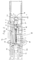
- the submachine gun shown in Figs. 1 to 4 has Housing 11, in which a barrel 13 is attached to the his rear end has a cartridge chamber in the a cartridge 14 is insertable. Behind the barrel 13 is a in the longitudinal direction movable, unlocked Closure 15 (ground closure) arranged in the housing 11th is guided and by a (not shown) closing spring pushed forward and against the barrel 13. Laterally from the shutter 15, when this in its front End position is an ejection window 12 in the housing 11th educated.
- the shutter 15, which is also shown in Fig. 5, is in the middle of the length of a firing pin 3 interspersed, which loads a firing pin spring 1 to the rear in such a way, that he seeks to take a position in which the Rear striker end 10 from the rear End face of the closure 15 by a supernatant Y after protrudes behind (Fig. 3).
- a cock 9 pivotally mounted which in Figs. 3 and 4 is indicated only very schematically.
- This cock 9 can be from a clamping position, in which its upper end with Distance behind the front end position of the closure is arranged (Fig. 3) in a tee-off position, which is shown in Fig. 4 and in which the cock 9 on the to the rear beyond the closure 15 projecting, rear Striker end 10 hits; This will be the Firing pin 3 thrown forward, hits the Primer of the cartridge 14 and fires this off (Fig. 4).
- a weapon is from the state of the art known.
- the closure 15 is also an extractor and Safety device in the form of a leaf spring 16th attached, whose rear end has a projection, engages in front of an end collar 20 of the firing pin 3 and prevents this from moving forward.
- the tee off Cock 9 meets an inclined surface on the leaf spring 16th and deflects them so that their projection from the Engagement with the collar 20 is moved and only then Firing pin immediately before the hammer is hit 9 is released.
- This leaf spring 16 is in German Patent application 197 02 374.6-15 described by the applicant; the disclosure of this patent application is by the Reference expressly included in the present documentation added.
- this leaf spring is the 16th modified so that they do not the firing pin 3 in completely fixed his backward situation, but one to him certain mobility (over the route X + Y) in Leads longitudinally forward.
- the firing pin 3 is from the leaf spring 16, however, still prevented with its tip over the front face of the Fastener 15 move out, as long as not the cock 9 by its knocking off the leaf spring 16 from the engagement with the firing pin 3 has pressed.
- the front end of the Leaf spring 16 is designed as an extractor.
- the closure On the leaf spring 16 opposite longitudinal side the closure has a in the front end face opening longitudinal groove 18, in which a Ausierervorsprung 17 engages the stationary at a, in the housing 11th fixed engaging part 8 is formed, which as Sheet steel component is formed, with its front End in a recess in the outside of the barrel 13 engages near the rear end.
- the firing pin 3 points, seen from the front to the rear (in the drawing from left to right), a thin point on, subsequently a thicker, but slender shaft, the approximately to the middle of the length extension of the firing pin 3 ranges, followed by a thickened, cylindrical Section 21 and finally the already mentioned Endbund 20.
- the firing pin spring 1 is on the slender shaft guided and supported with its rear end on the Paragraph, which marks the transition between the slender stem and the thickened portion 21 forms.
- the sleeve 4 and the stop piece 6 each have one lateral projection on, which is guided in the longitudinal groove 18 is; In addition, the stop piece 6 is stationary in the lock 15 held by a mounting pin 7.
- the sleeve 4 has, starting from the rear end surface, a Blind hole on, as well as the stopper piece 6, in which the blind bore from the front end surface starting.
- the Counter spring 5 penetrates into each of the blind holes and rests on the respective bore end face.
- the sleeve 4 sits with its front end surface a paragraph in the longitudinal bore in the closure 15.
- the Striker pin 1 is supported by its front end another paragraph in said longitudinal bore from, with its rear end on the heel of the firing pin.
- the opposing spring 5 is stronger than the firing pin spring 1, so that the opposing spring 5 is always the sleeve 4 against the effect seeks to push the firing pin spring 1 forward. If the closure is e.g. removed from the weapon, as in Fig. 5, then the sleeve 4 sits on the associated Paragraph of the closure longitudinal bore on and presses the Circlip 2 and thus the firing pin 3 forward, so that the rear firing pin end 10 by the dimension X towards the rear end of the shutter 15 forward is offset. In this position of the Schagbolzens 3, the e.g. is shown in Fig. 2, the tap 9 hits when knocked off on the rear surface of the shutter 15, without the rear striker end 10 to achieve.
- the housing 11 On the inside of the ejection window the housing 11 has a stationary engagement part 8 Sheet steel on, with a projection 17 in the longitudinal groove 18 of the shutter 15 is immersed.
- the leading edge 19 of this Projection 17 forms the ejector edge; if the shutter 15 with a cartridge 14 or an empty cartridge case moved backwards, then the edge of this hits Cartridge 14 or cartridge case on the ejection window 12 opposite side on the ejector edge 19 and is ejected by this.
- the projection 17 On the opposite of the ejector edge 19 Rear side, the projection 17 has another Function edge, which is set up in the engage lateral projection of the sleeve 4 and then this and thus the sleeve 4 at another To prevent forward movement.
- This functional edge of the Engagement part 8 meets the lateral projection of Sleeve 4 on, when the shutter is still around the distance X + Y of his front end position is removed, which he shot should take.
- the front end of the engaging part 8 engages in one Recess of the barrel 13, so that the rear Function edge of the projection 17 is always in fixed distance from the barrel 13 and thus of the The situation remains that the bottom of the cartridge 14 at gunpoint occupies.
- the leaf spring 16 engages with the projection in her rear area the collar 20 of the firing pin 3.
- the sleeve 4 is in its front end position and takes it over the locking ring 2 the firing pin 3 so far front, that is its rear end 10 around the distance X opposite the front end of the shutter 15 is moved forward is. Should now stop the tap 9 accidentally, then he would hit the back end of the shutter 15, but do not touch the firing pin 3.
- the in the longitudinal groove 18 guided lateral projection of the sleeve 4 is of the rear functional edge of the projection 17 of the Engaging part 8 removed by the distance Z, the Closure must cover at least, without the Cartridge 14 may be fired.
- top o. The like. go out from the horizontal position of use of the weapon when Shot, wherein the weft direction points to "front” (in the Drawing to the left).
- a breaker mechanism is provided, which is the triggering Connection between the trigger and the tap only then produces or with continuous fire the cock only then triggers, when the shutter is fully closed. This will be this Breaker mechanism by the position of the closure activated, so that basically the delivery of a shot only possible if the shutter completely closed is.
Abstract
Description
Die Erfindung betrifft eine Handfeuerwaffe mit einem Verschluß, der beweglich in eine für das Zünden einer Patrone eingerichtete Endlage beweglich ist, einem im Verschluß längs einer Bewegungsbahn beweglich gelagerten Schlagbolzen mit einer diesen nach hinten belastenden Schlagbolzenfeder (1) und einer Abschlageinrichtung, die von einer Abzugseinrichtung auslösbar ist und dazu eingerichtet ist, zum Zünden einer Patrone auf das von dieser abgewandte Schlagbolzenende aufzuschlagen und dadurch den Schlagbolzen in seine Zündlage zu verbringen. Eine derartige Waffe ist aus der US 1 363 040 bekannt.The invention relates to a handgun with a Lock moving into one for igniting one Cartridge fitted end position is movable, one in Closure along a trajectory movably mounted firing pin with a striker pin spring (1) loading it backwards and one Demolition device by a trigger device is triggered and is set up to ignite a Cartridge on the side facing away from this firing pin end aufzuschlagen and thereby the firing pin in his To spend ignition position. Such a weapon is out No. 1,363,040.
Im folgenden verwendete Lagebegriffe wie "oben" o. dgl. gehen aus von der horizontalen Gebrauchslage der Waffe beim Schuß, wobei die Schußrichtung nach "vorne" weist (in der Zeichnung nach links).In the following used terms such as "top" o. The like. go out from the horizontal position of use of the weapon when Shot, wherein the weft direction points to "front" (in the Drawing to the left).
Bei vielen Selbstlade-Handfeuerwaffen ist ein Hahn vorgesehen, der bei Betätigen des Abzuges abschlägt und auf das hintere Ende eines Schlagbolzens aufschlägt, der den Verschluß durchsetzt und durch eine Schlagbolzenfeder derart nach hinten gedrückt wird, daß sein hinteres Ende um eine Überstandstrecke aus dem Verschluß heraussteht und sein vorderes Ende, die Spitze, mindestens um die Überstandstrecke gegenüber der vorderen Stirnfläche des Verschlusses zurückgesetzt ist. Beim Aufschlag des Hahnes auf das hintere Ende des Schlagbolzens wird dieser beschleunigt und bewegt sich aufgrund seiner Massenträgheit gegen die Kraft der Schlagbolzenfeder nach vorne, wo er aus der Stirnfläche des Verschlusses, dem Stoßboden, mit seiner Spitze austritt und auf das Zündhütchen der Patrone treffen kann, die von vorne her am Stoßboden aufsitzt. Anstelle eines Hahnes kann auch ein Schlagstück vorgesehen sein, das nicht, wie ein Hahn, um eine feste Achse schwenkbar ist, sondern z.B. in einer geradlinigen Bewegungbahn geführt und unter Last einer Schlagfeder beweglich ist. In folgenden wird der einfacheren Darstellung halber, aber ohne jede Einschränkung, nur von einem "Hahn" gesprochen.Many self-loading handguns have a tap provided that abschlägt when pressing the trigger and on the rear end of a firing pin hits the Closure interspersed and by a firing pin spring pushed backwards so that its rear end to a protrusion line protrudes from the shutter and its front end, the tip, at least around the Projection distance from the front face of the Lock is reset. At the serve of the cock on the rear end of the striker this is accelerates and moves due to its inertia against the force of the firing pin spring forward, where he out the face of the lock, the push bottom, with its Exit the tip and hit the primer of the cartridge can sit on the bottom of the shock from the front. Instead of a cock can also be provided a hammer, the not, as a cock is pivotable about a fixed axis, but e.g. guided in a straight-line movement path and is movable under load a striker. In the following is for the sake of simplicity, but without any Restriction, only spoken by a "cock".
Um zu verhindern, daß der Hahn bereits dann abschlägt, auf das Schlagbolzenende auftrifft und die Zündung der Patrone veranlaßt, bevor der Verschluß ganz geschlossen ist, ist in der Abzugseinrichtung ein Unterbrechermechanismus vorgesehen, der die auslösende Verbindung zwischen dem Abzug und dem Hahn erst dann herstellt oder bei Dauerfeuer den Hahn erst dann auslöst, wenn der Verschluß voll geschlossen ist. Dabei wird dieser Unterbrechermechanismus durch die Lage des Verschlusses angesteuert, so daß grundsätzlich die Abgabe eines Schusses nur dann möglich ist, wenn der Verschluß vollständig geschlossen ist.To prevent the tap from knocking off already, open the firing pin end hits and the ignition of the cartridge caused before the shutter is completely closed is in the trigger means a breaker mechanism provided that the triggering connection between the Deduction and the cock only then produces or with continuous fire the cock only triggers when the shutter is full closed is. At the same time, this breaker mechanism becomes controlled by the position of the shutter, so that In principle, the delivery of a shot only possible is when the shutter is completely closed.
Es können sich jedoch Herstellungstoleranzen, Verschmutzung und/oder Abnutzung auf den Unterbrechungsmechanismus oder der Bruch eines Bauteils so auswirken, daß dieser bereits die Verbindung von Abzug und Hahn oder dessen Auslösung bei Dauerfeuer dann herstellt, wenn der Verschluß noch offen oder unverriegelt oder erst teilweise verriegelt ist.However, there may be manufacturing tolerances, pollution and / or wear on the interrupt mechanism or the breakage of a component so that this already the connection of trigger and cock or its triggering at Continuous fire then produces when the shutter is still open or unlocked or partially locked.
Ausgehend von dieser Problemlage liegt der Erfindung die Aufgabe zugrunde, eine zusätzliche Einrichtung vorzusehen, die zwangsweise das Auslösen eines Schusses erst dann ermöglicht, wenn der Verschluß die Patrone ausreichend weit ins Patronenlager eingeführt hat.Based on this problem situation, the invention is the Task is to provide an additional device, the forcible triggering a shot only then allows if the shutter the cartridge sufficiently far introduced into the chamber.
Diese Aufgabe wird durch die Merkale des Ansprüchs 1 gelöst. Es ist dem nach eine von der Abzugseinrichtung unabhängige, zusätzliche Einrichtung zum Verhindern der durch die Abschlageinrichtung bzw. den Hahn ausgelösten Bewegung des Schlagbolzens in seine Zündlage vorgesehen.This object is achieved by the features of Ansprüchs 1. It is the one independent of the trigger device, additional Device for preventing the by the Demolition device or the cock triggered movement of the Firing pin provided in its firing position.
Diese Einrichtung ist dazu eingerichtet, diese Bewegung des Schlagbolzens in seine Zündlage erst dann zuzulassen, wenn der Verschluß seine Endlage erreicht hat und somit die Patrone soweit in das Patronenlager eingeführt hat, daß diese ausreichend abgestützt wird.This facility is set up to handle this movement Only allow firing pin in its firing position, if the shutter has reached its end position and thus the Cartridge so far introduced into the chamber, that this is sufficiently supported.
Die Erfahrung hat nämlich ergeben, daß die Abzugseinrichtung, die eigentlich das vorzeitige Abfeuern einer Patrone verhindern sollte, aus den verschiedensten Gründen hierzu nicht mit letzter Zuverlässigkeit imstande ist. Die Erfindung sorgt deshalb für eine gesonderte Einrichtung, deren Zweck es ist, den Schlagbolzen so lange am Erreichen seiner Zündlage zu hindern, bis der Verschluß bis zum Sicherheitsmaß seine Endlage erreicht hat. Hierbei ist es dem Fachmann klar, daß die Endlage kein Punkt längs der Bewegungstrecke des Verschlusses ist, sondern ein Toleranzfeld, das allerdings sehr eng ist.Experience has shown that the Trigger mechanism, which is actually the premature firing a cartridge should prevent, from the most diverse Reasons not able to do so with the utmost reliability is. The invention therefore provides for a separate Device whose purpose is to use the firing pin for so long to prevent reaching its ignition position until the shutter reached its final position until the security measure. in this connection it is clear to those skilled in the art that the end position no point along the movement distance of the shutter is, but a Tolerance field, which is very narrow.
Bei dieser Erfindung ist auch gewährleistet, daß z. B. durch Prellen des Verschlusses ein bestimmtes Öffnen des Verschlusses vorkommen kann, der Schlagbolzen aber sofort aus seinem Beaufschlagungsbereich des Hahns gesteuert wird.In this invention, it is also ensured that z. B. by bouncing the shutter a certain opening of the However, the firing pin can occur immediately is controlled from its loading area of the tap.
Die, zusätzliche Einrichtung könnte etwa aus einem Kipphebel bestehen, der schwenkbar im Verschluß gelagert ist, durch eine Feder mit seinem einen Schenkel in sperrenden Eingriff mit dem Verschluß drückbar ist und mit seinem anderen Ende an der vorderen Stirnfläche oder einer Seitenfläche des Verschlusses über diesen übersteht. Im Bewegungsweg dieses überstehenden Schenkels ist am Lauf oder am Gehäuse eine Anschlagfläche vorgesehen, gegen die beim Schließen des Verschlusses dieser überstehende Schenkel anläuft und dabei den anderen Schenkel des Kipphebels aus dem Eingriff mit dem Schlagbolzen hebt. Die Anordnung der Anschlagfläche ist dabei so, daß der Schlagbolzen erst dann freigegeben ist, wenn der Verschluß das Toleranzfeld seiner Endlage erreicht hat.The, additional facility could be about consist of a rocker arm, the pivoting in the closure is stored by a spring with his one leg in locking engagement with the closure is depressible and with its other end on the front face or one Side surface of the closure over this protrudes. in the Movement path of this protruding leg is on the barrel or on the housing a stop surface provided against the when closing the shutter this protruding Thigh starts while doing the other leg of the Rocker arm out of engagement with the firing pin lifts. The Arrangement of the abutment surface is such that the Firing pin is released only when the shutter has reached the tolerance field of its final position.
Allerdings ist ein solcher Mechanismus hohen Kräften ausgesetzt, die auf gleitend bewegte Teile einwirken und somit erheblichen Verschleiß verursachen können; insbesondere kann dieser Mechanismus durch Einwirkung der Abschlageinrichtung ausgeschlagen werden.However, such a mechanism is high forces exposed, which act on sliding moving parts and thus can cause significant wear; In particular, this mechanism can be achieved by the action of Knockdown device are knocked out.
Erfindungsgemäß ist daher weiter vorgesehen, den Schlagbolzen dann, wenn ein Zünden verhindert werden soll, aus dem Bewegungsbereich der Abschlageinrichtung zu verbringen.According to the invention is therefore further provided, the firing pin then, if ignition should be prevented from the range of motion to spend the tee-off facility.
Es wäre auch möglich, die zur Zündung eingerichtete Schlagbolzenspitze aus einer Lage gegenüber dem Zündhütchen der Patrone zu entfernen, doch könnte dann ein Abschlagen der Abschlageinrichtung vielleicht zu Schäden am Schlagbolzen führen.It would be too possible, the firing point set up for ignition from a position opposite the primer of the cartridge remove, but then could be a knock off the Demolition device may damage the firing pin to lead.
Zwar könnte der Schlagbolzen so gekippt werden, daß er mit seinem hinteren Ende quer zu seiner Bewegungsrichtung versetzt wird, wie das von gewissen Sicherungen her bekannt ist. Erfindungsgemäß wird aber der Schlagbolzen um ein solches Maß nach vorne versetzt, daß er zuverlässig noch hinter seiner Zündlage liegt, aber so weit in den Verschluß eintaucht, daß sein hinteres Ende vor dem Kontakt mit dem Hahn oder einem Schlagstück durch Ausbildungen des Verschlusses, bevorzugt die hintere Endfläche des Verschlusses, geschützt ist. Diese Ausgestaltung ist besonders bei einer Waffe zu bevorzugen, bei der der Hahn völlig innerhalb des Gehäuses liegt, so daß nicht die Gefahr besteht, daß ein Fremdkörper zwischen Hahn und Schlagbolzen gerät und dann doch noch für eine Zündung sorgen könnte. Although the firing pin could be tilted so that it with its rear end transverse to its direction of movement is offset, as known from certain backups ago is. According to the invention but the firing pin is such Measure moved forward, that he reliably still behind its firing position lies, but so far in the lock dips in that his rear end before contact with the Rooster or a hammer by training of the Closure, preferably the rear end face of the Closure, is protected. This embodiment is especially with a weapon to prefer, where the cock is completely within the housing, so that not the There is a risk that a foreign body between cock and Firing pin device and then still for an ignition could provide.
Der Schlagbolzen könnte in die beschriebene Sicherheitlage durch die auf den Verschluß einwirkende Schließfeder verbracht werden. Nach der Erfindung ist jedoch eine Gegenfeder vorgesehen, die sich zwischen Verschluß und Schlagbolzen abstützt, diesen jedoch nur bis in seine Sicherheitlage drücken kann. Die Federkraft der Gegenfeder ist hierzu höher als die der verwendeten Schlagbolzenfeder. Bei der Vorwärtsbewegung des Verschlusses tritt, kurz bevor dieser seine Endlage erreicht, die Gegenfeder mit einer ortsfesten Gehäuseausbildung, etwa einem Gehäusevorsprung o. dgl., in Eingriff und bricht hierdurch ihre Einwirkung auf den Schlagbolzen ab, der nun durch Wirkung seiner Schlagbolzenfeder soweit zurückbewegt werden kann, daß der Hahn dann unbehindert auf den Schlagbolzen aufschlagen kann.The firing pin could in the described security situation by the closing spring acting on the closure be spent. However, according to the invention is one Provided counter spring, extending between shutter and Striker supported, but this only up in his Can press security. The spring force of the opposing spring This is higher than that of the firing pin spring used. In the forward movement of the shutter occurs just before it reaches its final position, the Counter spring with a stationary housing education, about a housing projection o. The like., Engages and breaks thereby their action on the firing pin off, the now as far as moved back by the action of his firing pin spring can be that the cock then unhindered on the Can strike the firing pin.
Die US 1 363 040 A, die eine Pistole beschreibt, mit
- einem Verschluß, der beweglich in einem Gehäuse in eine für das Zünden einer Patrone eingerichtete Endlage beweglich ist,
- einem im Verschluß längs einer geradlinigen Bewegungsbahn beweglich gelagerten Schlagbolzen mit einer diesen nach hinten belastenden Schlagbolzenfeder, und
- einer Abschlageinrichtung, die von einer Abzugseinrichtung auslösbar ist und dazu eingerichtet ist, zum Zünden einer Patrone auf das von dieser abgewandte Schlagbolzenende aufzuschlagen und dadurch den Schlagbolzen in seine Zündlage zu verbringen.
- a closure which is movably movable in a housing into an end position adapted for firing a cartridge,
- a firing pin movably mounted in the shutter along a rectilinear trajectory with a firing pin spring loading it backwards, and
- a knock-off device, which is triggered by a trigger device and is adapted to strike for igniting a cartridge on the side facing away from this firing pin end and thereby spend the firing pin in its firing position.
Bei dieser Pistole ist
- eine von der Abzugseinrichtung unabhängige, zusätzliche Einrichtung zum Verhindern der durch die Abschlageinrichtung ausgelösten Bewegung des Schlagbolzens in die Zündlage vorgesehen, und
- die Einrichtung dazu eingerichtet, die Bewegung des Schlagbolzens in seine Zündlage erst dann zuzulassen, wenn der Verschluß seine Endlage erreicht hat.
- an independent of the trigger device, additional device for preventing the triggered by the knock-off movement of the firing pin provided in the ignition position, and
- the device adapted to allow the movement of the firing pin in its firing position only when the shutter has reached its end position.
Bei dieser bekannten Pistole ist aber nicht die Einrichtung als Gegenfeder ausgebildet, die mit einer gehäusefesten Ausbildung zusammenwirkt.In this known pistol but is not the device formed as a counter-spring, with a housing-fixed Training cooperates.
Aus der GB5124 A.D. 1914 ist zwar eine Gegenfeder bekannt, die allerdings nicht mit einer gehäusefesten Ausbildung zusammenwirkt.From GB5124 A.D. 1914 Although a counter spring is known, but not with a housing-proof training interacts.
Die ortsfeste Gehäuseausbildung könnte etwa als Einbuchtung eines aus Blech gebildeten Gehäuses hergestellt sein; bevorzugt ist diese Gehäuseausbildung jedoch als eigenes Bauteil ausgebildet, das dementsprechend aus einem für seinen Zweck optimierten, hochverschleißfesten Material hergestellt sein kann. Dieses gesonderte Bauteil kann unlösbar im Gehäuse befestigt sein, etwa durch Verbundguß, kann aber auch lösbar angebracht sein, so daß es, wenn es verschlissen oder beschädigt sein sollte, ohne weiteres durch ein neues Bauteil ersetzt werden kann oder auch vor dem endgültigen Einbau eingepaßt werden kann. Bevorzugt ist dieses Bauteil mit einer Eingriffsausbildung versehen, die in eine Gegenausbildung am Lauf eingreift, so daß der kritische Abstand zwischen dem hinteren Ende des Laufes und somit des Patronenlagers und der Fläche oder Kante des Bauteils, das die Wirkung der Gegenfeder aufhebt, mühelos mit einem sehr engen Toleranzfeld eingehalten werden kann.The stationary housing education could be about as indentation be made of a sheet formed housing; However, this housing training is preferred as its own Part formed, which accordingly consists of a for its purpose optimized, highly wear-resistant material can be made. This separate component can be permanently attached in the housing, such as by composite casting, but can also be releasably attached, so that if it worn or damaged, without further ado can be replaced by a new component or even before the final installation can be fitted. Is preferred this component provided with an engagement training, the engages in a counter training on the barrel, so that the critical distance between the back end of the barrel and thus the cartridge chamber and the surface or edge of the Component that cancels the action of the opposing spring effortlessly can be maintained with a very narrow tolerance field.
Bevorzugt ist das genannte, gesonderte Bauteil als Patronenausstoßer ausgebildet; der ohnehin aus verschleißfestem Material gebildet sein muß und an dem erfindungsgemäß eine Fläche oder Kante ausgebildet ist, die zum Abfangen der Gegenfeder oder des ihr zugeordneten Teils dient. Es kann somit das genannte, gesonderte Bauteil aus optimalem Material bereitgestellt werden, ohne daß deshalb ein zusätzliches Bestandteil der Waffe erforderlich ist. Es ist demnach möglich, eine Waffe der eingangs genannten Art auf höchst wirtschaftliche Weise mit einer neuartigen Sicherheitseinrichtung zu versehen, die von der Abzugseinrichtung völlig unabhängig ist, und damit auch von der Summierung von Toleranzen und dem Verschleiß, die bei einer Abzugseinrichtung letztlich kaum zu vermeiden sind.Preferably, said separate component is as Cartridge ejector formed; anyway off wear-resistant material must be formed and on the According to the invention, a surface or edge is formed, the for catching the opposing spring or its associated part serves. It can thus be the said, separate component be provided optimal material without that, therefore an additional part of the weapon is required. It is therefore possible, a weapon of the type mentioned in a most economical way with a novel Safety device to be provided by the Discharge device is completely independent, and therefore also of the summation of tolerances and the wear at a trigger device are ultimately difficult to avoid.
Der Gegenstand der Erfindung wird anhand der beigefügten,
schematischen Zeichnung beispielsweise noch näher
erläutert; in dieser zeigt:
Die in Fig. 1 bis 4 gezeigte Maschinenpistole weist ein
Gehäuse 11 auf, in dem ein Lauf 13 befestigt ist, der an
seinem hinteren Ende ein Patronenlager aufweist, in das
eine Patrone 14 einführbar ist. Hinter dem Lauf 13 ist ein
in dessen Längsrichtung beweglicher, unverriegelter
Verschluß 15 (Masseverschluß) angeordnet, der im Gehäuse 11
geführt ist und durch eine (nicht gezeigte) Schließfeder
nach vorne und gegen den Lauf 13 gedrückt wird. Seitlich
vom Verschluß 15, wenn sich dieser in seiner vorderen
Endlage befindet, ist ein Auswurffenster 12 im Gehäuse 11
ausgebildet.The submachine gun shown in Figs. 1 to 4 has
Der Verschluß 15, der auch in Fig. 5 gezeigt ist, ist
mittig der Länge nach von einem Schlagbolzen 3 durchsetzt,
den eine Schlagbolzenfeder 1 nach hinten derart belastet,
daß er danach trachtet, eine Lage einzunehmen, in der das
hintere Schlagbolzenende 10 aus der rückwärtigen
Stirnfläche des Verschlusses 15 um einen Überstand Y nach
hinten heraussteht (Fig. 3).The
Unterhalb des Verschlusses 15 und hinter dessen vorderer
Endlage ist ein Hahn 9 schwenkbar gelagert, der in den Fig.
3 und 4 nur sehr schematisch angedeutet ist. Dieser Hahn 9
kann aus einer Spannlage, in der sein oberes Ende mit
Abstand hinter der vorderen Endlage des Verschlusses
angeordnet ist (Fig. 3) in eine Abschlaglage abschlagen,
die in Fig. 4 gezeigt ist und in der der Hahn 9 auf das
nach hinten über den Verschluß 15 überstehende, hintere
Schlagbolzenende 10 aufschlägt; hierdurch wird der
Schlagbolzen 3 nach vorne geschleudert, trifft auf das
Zündhütchen der Patrone 14 und feuert dieses dadurch ab
(Fig. 4). Eine solche Waffe ist aus dem stand der Technik
bekannt.Below the
Im Verschluß 15 ist ferner eine Auszieher- und
Sicherungseinrichtung in Form einer Blattfeder 16
angebracht, deren hinteres Ende einen Vorsprung aufweist,
der vor einem Endbund 20 des Schlagbolzens 3 eingreift und
diesen an der Vorwärtsbewegung hindert. Der abschlagende
Hahn 9 trifft auf eine Schrägfläche an der Blattfeder 16
und lenkt sie derart aus, daß deren Vorsprung aus dem
Eingriff mit dem Bund 20 bewegt wird und erst dadurch der
Schlagbolzen unmittelbar vor dem Aufschlagen des Hahnes 9
freigegeben wird. Diese Blattfeder 16 ist in der deutschen
Patentanmeldung 197 02 374.6-15 der Anmelderin beschrieben;
die Offenbarung dieser Patentanmeldung wird durch die
Bezugnahme ausdrücklich in die vorliegenden Unterlagen mit
aufgenommen. Bei der Erfindung ist diese Blattfeder 16
derart modifiziert, daß sie den Schlagbolzen 3 nicht in
seiner hintersten Lage völlig festlegt, sondern ihm eine
gewisse Beweglichkeit (über die Strecke X + Y) in
Längsrichtung nach vorne beläßt. Der Schlagbolzen 3 wird
von der Blattfeder 16 jedoch nach wie vor daran gehindert,
sich mit seiner Spitze über die vordere Stirnfläche des
Verschlusses 15 hinauszubewegen, solange nicht der Hahn 9
durch sein Abschlagen die Blattfeder 16 aus dem Eingriff
mit dem Schlagbolzen 3 gedrückt hat. Das vordere Ende der
Blattfeder 16 ist als Auszieher ausgebildet.In the
Auf der der Blattfeder 16 gegenüberliegenden Längsseite
weist der Verschluß eine in dessen vordere Stirnfläche
einmündende Längsnut 18 auf, in die ein Ausstoßervorsprung
17 eingreift, der an einem ortsfesten, im Gehäuse 11
befestigten Eingriffsteil 8 ausgebildet ist, das als
Stahlblech-Bauteil ausgebildet ist, das mit seinem vorderen
Ende in eine Aussparung in der Außenseite des Laufes 13
nahe dessen hinterem Ende eingreift. Wenn sich der
Verschluß 15 nach einem Schuß mit der leeren Patronenhülse
zurückbewegt, läuft die Längsnut 18 über dem Vorsprung 17
nach hinten, bis der Boden der Patronenhülse gegen die
Vorderkante 19 des Vorsprungs 17 trifft und dadurch
ausgestoßen wird, wobei sie durch das Auswurffenster 12
ausgeworfen wird.On the
Der Schlagbolzen 3 weist, von vorne nach hinten gesehen (in
der Zeichnung von links nach rechts), eine dünne Spitze
auf, nachfolgend einen dickeren, aber schlanken Schaft, der
etwa bis zur Mitte der Längenerstreckung des Schlagbolzens
3 reicht, nachfolgend einen verdickten, zylindrischen
Abschnitt 21 und abschließend den bereits erwähnten Endbund
20. Die Schlagbolzenfeder 1 ist auf dem schlanken Schaft
geführt und stützt sich mit ihrem hinteren Ende auf dem
Absatz ab, der den Übergang zwischen dem schlanken Schaft
und dem verdickten Abschnitt 21 bildet. The
Von vorne her sind aufeinanderfolgend ein Anschlagstück 6
mit seiner Längs-Durchgangsbohrung, eine schraubenförmige
Gegenfeder 5 und eine Hülse 4 mit ihrer LÄngs-Durchgangsbohrung
auf den Schlagbolzen 3 aufgeschoben und
unter leichtem Zusammendrücken der Gegenfeder 5 nach hinten
gedrückt; anschließend wird ein Sicherungsring 2
angebracht, der in einer Ringnut sitzt, die im Bereich des
Übergangs zwischen dem Schaft und dem verdickten Abschnitt
21 des Schlgbolzens 3 in diesen eingebracht ist. Dieser
Sicherungsring 2 bildet einen vorderen Anschlag für die
Hülse 4 und hält die Teile als Baugruppe zusammen.From the front are successively a stop piece. 6
with its longitudinal through-hole, a
Die Hülse 4 und das Anschlagstück 6 weisen jeweils einen
seitlichen Vorsprung auf, der in der Längsnut 18 geführt
ist; außerdem ist das Anschlagstück 6 ortsfest im Verschluß
15 mittels eines Montagestiftes 7 gehalten. Die Hülse 4
weist, von der hinteren Endfläche ausgehend, eine
Sackbohrung auf, ebenso wie das Anschlagstück 6, bei dem
die Sackbohrung von der vorderen Endfläche ausgehend. Die
Gegenfeder 5 dringt in jede der Sackbohrungen ein und
stützt sich auf der jeweiligen Bohrungs-Endfläche ab.
Außerdem sitzt die Hülse 4 mit ihrer vorderen Endfläche auf
einem Absatz in der Längsbohrung im Verschluß 15 auf. Die
Schlagbolzenfeder 1 stützt sich mit ihrem vorderen Ende auf
einem weiteren Absatz in der genannten Längsbohrung ab, mit
ihrem hinteren Ende auf dem Absatz des Schlagbolzens.The
Die Gegenfeder 5 ist kräftiger als die Schlagbolzenfeder 1,
so daß die Gegenfeder 5 stets die Hülse 4 gegen die Wirkung
der Schlagbolzenfeder 1 nach vorne zu drücken trachtet.
Wenn der Verschluß z.B. aus der Waffe ausgebaut ist, wie in
Fig. 5 gezeigt, dann sitzt die Hülse 4 auf dem zugehörigen
Absatz der Verschluß-Längsbohrung auf und drückt dabei den
Sicherungsring 2 und damit dem Schlagbolzen 3 nach vorne,
so daß das hintere Schlagbolzenende 10 um das Maß X
gegenüber dem hinteren Ende des Verschlusses 15 nach vorne
versetzt ist. In dieser Lage des Schagbolzens 3, die z.B.
in Fig. 2 gezeigt ist, trifft der Hahn 9 beim Abschlagen
auf die hintere Fläche des Verschlusses 15 auf, ohne das
hintere Schlagbolzenende 10 erreichen zu können.The opposing
Auf der dem Auswurffenster gegenüberliegenden Innenseite
weist das Gehäuse 11 ein ortsfestes Eingriffsteil 8 aus
Stahlblech auf, mit einem Vorsprung 17, der in die Längsnut
18 des Verschlusses 15 eintaucht. Die Vorderkante 19 dieses
Vorsprungs 17 bildet die Ausstoßerkante; wenn der Verschluß
15 mit einer Patrone 14 oder einer leeren Patronenhülse
nach hinten bewegt wird, dann trifft der Rand dieser
Patrone 14 oder Patronenhülse auf der dem Auswurffenster 12
gegenüberliegenden Seite auf die Ausstoßerkante 19 und wird
durch dieses ausgeworfen.On the inside of the ejection window
the
Auf der von der Ausstoßerkante 19 entgegengesetzten
Rückseite weist der Vorsprung 17 eine weitere
Funktionskante auf, die dazu eingerichtet ist, in den
seitlichen Vorsprung der Hülse 4 einzugreifen und dann
diesen und damit die Hülse 4 an einer weiteren
Vorwärtsbewegung zu hindern. Diese Funktionskante des
Eingriffsteils 8 trifft auf den seitlichen Vorsprung der
Hülse 4 auf, wenn der Verschluß noch um die Strecke X+Y von
seiner vorderen Endlage entfernt ist, die er beim Schuß
einnehmen soll.On the opposite of the
Das vordere Ende des Eingriffsteils 8 greift in eine
Aussparung des Laufes 13 ein, so daß die hintere
Funktionskante des Vorsprungs 17 sich stets in
festbleibender Entfernung vom Lauf 13 und damit von der
Lage bleibt, die der Boden der Patrone 14 bei Schuß
einnimmt.The front end of the
Nachfolgend wird die Wirkungsweise der voranstehend
beschriebenen Anordnung beschrieben:
Die Blattfeder 16 untergreift mit dem Vorsprung in ihrem
hinteren Bereich den Bund 20 des Schlagbolzens 3. Die Hülse
4 befindet sich in ihrer vorderen Endlage und nimmt dabei
über den Sicherungsring 2 den Schlagbolzen 3 so weit nach
vorne, daß sein hinteres Ende 10 um die Strecke X gegenüber
dem hinteren Ende des Verschlusses 15 nach vorne versetzt
ist. Sollte nun der Hahn 9 versehentlich abschlagen, dann
würde er auf das hintere Ende des Verschlusses 15 treffen,
aber den Schlagbolzen 3 nicht berühren. Der in der Längsnut
18 geführte seitliche Vorsprung der Hülse 4 ist von der
hinteren Funktionskante des Vorsprungs 17 des
Eingriffsteils 8 um die Strecke Z entfernt, die der
Verschluß noch mindestens zurücklegen muß, ohne daß die
Patrone 14 abgefeuert werden darf.The
In Fig. 2 hat sich der Verschluß 15 gegenüber seiner Lage
in Fig. 1 um die Strecke Z nach vorne bewegt; alle im
Verschluß 15 eingebauten Teile weisen dieselben
Relativlagen auf wie in Fig. 1; der Vorsprung der Hülse 4
hat die Funktionskante des Vorsprungs 17 des Eingriffsteils
8 erreicht.In Fig. 2, the
In Fig. 3 hat sich der Verschluß 15 gegenüber der in Fig. 2
gezeigten Lage um die Strecke X+Y nach vorne bewegt und
seine vorschriftsmäßige Endlage erreicht, in der die
Patrone 14 voll im Patronenlager sitzt. Dabei wurde die
Hülse 4 während der letzten Bewegungsphase von der
Funktionskante des Vorsprungs 17 des Eingriffsteils 8
festgehalten, so daß sie nun vom zugehörigen Absatz in der
Längsbohrung, die den Schlagbolzen 3 aufnimmt, entfernt
ist. Die Schlagbolzenfeder 1 belastet den Sicherungsring 2
und damit den Schlagbolzen 3 nach hinten, so daß der
Sicherungsring 2 noch immer gegen die vordere Stirnfläche
der Hülse 4 anliegt und das hintere Schlagbolzenende 10 um
die Strecke Y über das hintere Ende des Verschlusses 15
nach hinten übersteht. In Fig. 3, the
In Fig. 4 ist der Augenblick des Abfeuerns der Patrone 14
dargestellt; der Hahn 9 hat sich in Pfeilrichtung bis in
seiner vordere Endlage bewegt, hat dabei über die
Schrägfläche am hinteren Ende der Blattfeder 16 deren
Vorsprung aus dem Bewegungsweg des Bundes 20 des
Schlagbolzens 3 bewegt und hat auf das hintere
Schlagbolzenende 10 aufgeschlagen; der Schlagbolzen 3 wurde
durch diesen Aufschlag beschleunigt und gegen die Kraft der
Schlagbolzenfeder 1 nach vorne bis zum Auftreffen auf das
Zündhütchen der Patrone 14 bewegt. Die Gegenfeder 5 wirkt
dabei nicht auf den Schlagbolzen 3 ein, da sie über das
Anschlagstück 6 und den Montagestift 7 am Verschluß 15
abgestützt ist. Wenn sich nun der Verschluß 15 durch den
Rückstoß der abgeschossenen Patrone 14 nach hinten bewegt,
wird der Hahn 9 wieder gespannt und der Schlagbolzen 3 wird
durch die Gegenfeder 5 wieder so weit nach vorne gedrückt,
wie das in Fig. 1 und 2 gezeigt ist, sobald der Vorsprung
der Hülse 4 von der Funktionskante am Vorsprung 17 des
Eingriffsteils 8 freigekommen ist. Dabei gewährleistet der
einteilige Aufbau des Engriffsteils 8 und dessen fester
Eingriff in den Lauf 13 stets eine gleichbleibende Lage der
genannten Funktionskante.In Fig. 4, the moment of firing of the
Es kann sich Schmutz zwischen Lauf 13 und Verschluß 15
ansammeln, oder ein Fremdkörper kann ins Patronenlager
gelangen, der dann jeweils verhindert, daß der Verschluß 15
seine vordere Endlage noch ganz erreichen kann. Auch hier
verkleinert sich entsprechend der Überstand Y, so daß
letztlich dann, wenn die Verschlußlage nicht mehr die
gefahrlose Abgabe eines Schusses gewährleistet, auch kein
Schuß mehr abgegeben werden kann.It may be dirt between
Im folgenden verwendete Lagebegriffe wie "oben" o. dgl. gehen aus von der horizontalen Gebrauchslage der Waffe beim Schuß, wobei die Schußrichtung nach "vorne" weist (in der Zeichnung nach links).In the following used terms such as "top" o. The like. go out from the horizontal position of use of the weapon when Shot, wherein the weft direction points to "front" (in the Drawing to the left).
Bei vielen Selbstlade-Handfeuerwaffen ist ein Hahn vorgesehen, der bei Betätigen des Abzuges abschlägt und auf das hintere Ende eines Schlagbolzens aufschlägt, der den frei fliegenden Schlagbolzen durchsetzt und durch eine Schlagbolzenfeder derart nach hinten gedrückt wird, daß sein hinteres Ende um eine Überstandstrecke aus dem Verschluß heraussteht und sein vorderes Ende, die Spitze, mindestens um die Überstandstrecke gegenüber der vorderen Stirnfläche des Verschlusses zurückgesetzt ist. Beim Aufschlag des Hahnes auf das hintere Ende des Schlagbolzens wird dieser beschleunigt und bewegt sich aufgrund seiner Massenträgheit gegen die Kraft der Schlagbolzenfeder nach vorne, wo er aus der Stirnfläche des Verschlusses, dem Stoßboden, mit seinere Spitze austritt und gegebenenfalls auf das Zündhütchen der Patrone trifft, die von vorne her am Stoßboden aufsitzt.Many self-loading handguns have a tap provided that abschlägt when pressing the trigger and on the rear end of a firing pin hits the freely flying firing pin interspersed and by a Striker pin spring is pressed backwards so that its rear end around a projection distance from the Shutter protrudes and its front end, the tip, at least the overhang distance from the front End face of the closure is reset. At the Serve the tap on the back end of the firing pin this is accelerated and moves due to its Mass inertia against the force of the firing pin spring front, where he is from the end face of the closure, the Shock floor, with its tip exits and, where appropriate on the primer of the cartridge meets the front sitting on the bottom of the shock.
Um zu verhindern, daß der Hahn bereits dann abschlägt, auf das Schlagbolzenende auftrifft und die Zündung der Patrone veranlaßt, bevor der Verschluß ganz geschlossen ist, ist ein Unterbrechermechanismus vorgesehen, der die auslösende Verbindung zwischen dem Abzug und dem Hahn erst dann herstellt oder bei Dauerfeuer den Hahn erst dann auslöst, wenn der Verschluß voll geschlossen ist. Dabei wird dieser Unterbrechermechanismus durch die Lage des Verschlusses angesteuert, so daß grundsätzlich die Abgabe eines Schusses nur dann möglich ist, wenn der Verschluß vollständig geschlossen ist.To prevent the tap from knocking off already, open the firing pin end hits and the ignition of the cartridge caused before the shutter is completely closed is a breaker mechanism is provided, which is the triggering Connection between the trigger and the tap only then produces or with continuous fire the cock only then triggers, when the shutter is fully closed. This will be this Breaker mechanism by the position of the closure activated, so that basically the delivery of a shot only possible if the shutter completely closed is.
Dies gilt für alle unverriegelten Waffen, aber auch für verriegelte Waffen.This applies to all unlocked weapons, but also for locked weapons.
Claims (4)
- A self-loading small arm havingcharacterised in that the self-loading small arm is also provided witha slide (15), which is movable in a housing (11) into an end position set up for priming a cartridge (14),a firing pin (3) moveably mounted in the slide (15) along a path of movement with a firing pin spring (1) that loads it to the rear,a tripping device (9) which can be released by a trigger mechanism and to prime a cartridge (14) is set up to strike the end (10) of the firing pin further from said cartridge and thereby to move the firing pin into its priming position,a counter-spring (5), which is supported between the slide (15) and the firing pin (3) and forces said firing pin forwards opposite to the direction of loading by the firing pin spring (1) out of the range of action of the tripping device when the slide is open, anda structure fixed to the housing, which only acts at the end of the closing movement of the slide (15) on the counter-spring (5) so that this counter-spring uncovers the firing pin (3) so that it arrives in the range of action of the tripping device (9).
- A small arm according to Claim 1,
characterised in that the firing pin (3) can be moved into a position along its path of movement in which its end (10) closer to the tripping device (9) rests inside a structure of the slide (15) in a safety position which screens it from the action of the tripping device (9). - A small arm according to Claims 1 and 2,
characterised in that the structure fixed to the housing forms a protrusion (17) which is constructed on a component which is separately fixed by the housing (11) and preferably engages in the barrel (13). - A small arm according to Claim 3,
characterised in that the protrusion (17) comprises two edges extending transversely to the path of movement of the slide (15), of which the one further from the barrel (13) forms the structure fixed to the housing and the one closer to the barrel (13) forms the ejector.
Priority Applications (1)
| Application Number | Priority Date | Filing Date | Title |
|---|---|---|---|
| DK99908800T DK1064514T3 (en) | 1998-03-24 | 1999-01-19 | Impact Bolt Control |
Applications Claiming Priority (3)
| Application Number | Priority Date | Filing Date | Title |
|---|---|---|---|
| DE19812951 | 1998-03-24 | ||
| DE19812951A DE19812951C2 (en) | 1998-03-24 | 1998-03-24 | Firing pin safety in the lock |
| PCT/EP1999/000294 WO1999049272A1 (en) | 1998-03-24 | 1999-01-19 | Striking pin control mechanism |
Publications (2)
| Publication Number | Publication Date |
|---|---|
| EP1064514A1 EP1064514A1 (en) | 2001-01-03 |
| EP1064514B1 true EP1064514B1 (en) | 2005-03-30 |
Family
ID=7862155
Family Applications (1)
| Application Number | Title | Priority Date | Filing Date |
|---|---|---|---|
| EP99908800A Expired - Lifetime EP1064514B1 (en) | 1998-03-24 | 1999-01-19 | Striking pin control mechanism |
Country Status (7)
| Country | Link |
|---|---|
| US (1) | US6349495B1 (en) |
| EP (1) | EP1064514B1 (en) |
| AT (1) | ATE292273T1 (en) |
| CA (1) | CA2325504C (en) |
| DE (2) | DE19812951C2 (en) |
| ES (1) | ES2238824T3 (en) |
| WO (1) | WO1999049272A1 (en) |
Families Citing this family (18)
| Publication number | Priority date | Publication date | Assignee | Title |
|---|---|---|---|---|
| FI107759B (en) * | 1999-12-03 | 2001-09-28 | Sako Oy | Arms locking procedure and system |
| US20050115127A1 (en) * | 2003-02-19 | 2005-06-02 | Atilla Szabo | Extractor assembly for a semi-automatic handgun |
| DE20304023U1 (en) * | 2003-03-12 | 2003-05-22 | Roehm Gmbh | Dog training device |
| AT413443B (en) * | 2003-03-13 | 2006-02-15 | Gen Headquarters Of The Armed | PISTOL WITH BOLT SAFETY AND EJECTORS |
| DE102006037306B4 (en) | 2006-08-08 | 2009-12-03 | Rheinmetall Waffe Munition Gmbh | Device for triggering a firing pin |
| US8079168B2 (en) * | 2008-09-23 | 2011-12-20 | Browning | Firearm having an improved firing pin locking mechanism |
| US7963061B2 (en) * | 2008-09-23 | 2011-06-21 | Browning | Magazine plug |
| US8056280B2 (en) * | 2008-09-23 | 2011-11-15 | Browning | Firearm having an improved forearm fastening mechanism |
| US20100275486A1 (en) * | 2008-09-23 | 2010-11-04 | Browning | Shotgun having an improved shotshell feeding mechanism |
| US20100071541A1 (en) * | 2008-09-23 | 2010-03-25 | Browning | Firearm having an improved gas-operated action |
| AT507219B1 (en) | 2008-12-09 | 2010-03-15 | Caracal Internat L L C | PISTOL |
| US8296990B2 (en) | 2008-12-30 | 2012-10-30 | Smith & Wesson Corp. | Snap-on dovetail pistol sight |
| RU2443964C1 (en) * | 2010-09-13 | 2012-02-27 | Открытое акционерное общество "Завод им. В.А. Дегтярева" | Automatic small arms |
| US8939059B2 (en) * | 2012-10-16 | 2015-01-27 | Recoil Rebound, Llc | Progressive gun spring recoil system with high energy rebound |
| US9810496B2 (en) * | 2014-05-15 | 2017-11-07 | Savage Arms, Inc. | Semiautomatic firearm |
| DE102014111160A1 (en) * | 2014-06-16 | 2015-12-17 | Rheinmetall Waffe Munition Gmbh | Security system for a lock of a weapon |
| DE102015008797A1 (en) * | 2015-07-10 | 2017-01-12 | Rheinmetall Waffe Munition Gmbh | Case ejection device |
| US10907918B2 (en) | 2019-03-20 | 2021-02-02 | Smith & Wesson Inc. | Cartridge extractor |
Family Cites Families (17)
| Publication number | Priority date | Publication date | Assignee | Title |
|---|---|---|---|---|
| DE201609C (en) * | ||||
| DE107213C (en) * | ||||
| NL2787C (en) * | 1913-03-31 | |||
| US1455881A (en) * | 1917-07-20 | 1923-05-22 | Alva C Washburne | Firearm |
| US1363040A (en) * | 1917-12-01 | 1920-12-21 | Alva C Washburne | Firearm |
| US3889412A (en) * | 1973-11-26 | 1975-06-17 | Joseph E Filecci | Double action trigger mechanism for semi-automatic pistol |
| US3915811A (en) * | 1974-10-16 | 1975-10-28 | Oxy Metal Industries Corp | Method and composition for electroplating aluminum alloys |
| US4031648A (en) * | 1975-12-29 | 1977-06-28 | Thomas Frank S | Magazine safety and ejector |
| US4389919A (en) * | 1980-02-14 | 1983-06-28 | Remington Arms Company, Inc. | Firing pin block for firearm with a rotary breech bolt |
| US4589327A (en) * | 1983-03-28 | 1986-05-20 | Smith David E | Firing lock with safety system for self loading fire arms |
| DE3523531A1 (en) | 1984-07-02 | 1986-02-13 | Honda Giken Kogyo K.K., Tokio/Tokyo | VALVE ACTUATING DEVICE WITH LOCKING FUNCTION FOR AN INTERNAL COMBUSTION ENGINE |
| US4726136A (en) * | 1984-08-22 | 1988-02-23 | Dornaus & Dixon Enterprises | Firearm safety devices |
| CH662876A5 (en) * | 1984-10-25 | 1987-10-30 | Haemmerli Ag | Extraction device to a fist firearm. |
| EP0192343A3 (en) * | 1985-02-04 | 1987-05-20 | Victory Arms Co. Limited | Firing lock with safety system for self loading fire arms |
| DE3504519A1 (en) * | 1985-02-09 | 1986-08-14 | Mauser-Werke Oberndorf Gmbh, 7238 Oberndorf | Firing-bolt safety device for a wedge breech lock of a large-calibre gun |
| EP0751366A1 (en) * | 1995-06-30 | 1997-01-02 | Israel Military Industries Ltd. | A double action pistol with safety decocking mechanism |
| DE19702374C2 (en) * | 1997-01-23 | 2001-03-01 | Heckler & Koch Gmbh | Firing pin safety for a trigger device with a striking piece |
-
1998
- 1998-03-24 DE DE19812951A patent/DE19812951C2/en not_active Expired - Fee Related
-
1999
- 1999-01-19 ES ES99908800T patent/ES2238824T3/en not_active Expired - Lifetime
- 1999-01-19 DE DE59911843T patent/DE59911843D1/en not_active Expired - Fee Related
- 1999-01-19 AT AT99908800T patent/ATE292273T1/en not_active IP Right Cessation
- 1999-01-19 WO PCT/EP1999/000294 patent/WO1999049272A1/en active IP Right Grant
- 1999-01-19 CA CA002325504A patent/CA2325504C/en not_active Expired - Fee Related
- 1999-01-19 EP EP99908800A patent/EP1064514B1/en not_active Expired - Lifetime
-
2000
- 2000-09-22 US US09/669,064 patent/US6349495B1/en not_active Expired - Fee Related
Also Published As
| Publication number | Publication date |
|---|---|
| ATE292273T1 (en) | 2005-04-15 |
| CA2325504C (en) | 2005-06-28 |
| CA2325504A1 (en) | 1999-09-30 |
| DE59911843D1 (en) | 2005-05-04 |
| EP1064514A1 (en) | 2001-01-03 |
| ES2238824T3 (en) | 2005-09-01 |
| US6349495B1 (en) | 2002-02-26 |
| DE19812951C2 (en) | 2002-12-19 |
| WO1999049272A1 (en) | 1999-09-30 |
| DE19812951A1 (en) | 1999-09-30 |
Similar Documents
| Publication | Publication Date | Title |
|---|---|---|
| EP1064514B1 (en) | Striking pin control mechanism | |
| EP0816792B1 (en) | Trigger mechanism | |
| DE2442107A1 (en) | SEMI-AUTOMATIC FIRE ARM | |
| DE3505443C2 (en) | ||
| EP1825207A1 (en) | Multi-shot hand firearm | |
| EP1119736B1 (en) | Trigger device | |
| DE102014102672B4 (en) | Firearm, in particular handgun, and method of making a firearm | |
| EP0540778A1 (en) | Trigger mechanism for firearms | |
| DE19702374C2 (en) | Firing pin safety for a trigger device with a striking piece | |
| DE2413615A1 (en) | HANDGUN WITH SWIVELING LOCKING PART | |
| DE2745670A1 (en) | TRIGGER SAFETY FOR GUNS | |
| DE19732857C1 (en) | Safety action e.g. for rifle | |
| DE19959964B4 (en) | fuse | |
| DE19605851C2 (en) | Securing a firing pin of a firing pin and percussion device for a firearm | |
| EP2109747B1 (en) | Breech block for a drop-down barrel weapon | |
| DE102019124569B4 (en) | Lock system | |
| EP1535012B1 (en) | Small arm having a locked breech | |
| DE1553868B2 (en) | Electronically controlled trigger mechanism for handguns | |
| EP3176536A1 (en) | Weapon lock and hand gun with a such a weapon lock | |
| DE4013124C2 (en) | Firing pin safety device with integrated fall protection | |
| DE1166052B (en) | Emergency device with insert barrel for firing small caliber ammunition with automatic handguns, especially assault rifles with hammer ignition | |
| DE3323501C2 (en) | Handgun | |
| DE139766C (en) | ||
| DE7721573U1 (en) | REPAIR PULLER | |
| DE19500140A1 (en) | Rifle with trigger module contg. frame and hammer |
Legal Events
| Date | Code | Title | Description |
|---|---|---|---|
| PUAI | Public reference made under article 153(3) epc to a published international application that has entered the european phase |
Free format text: ORIGINAL CODE: 0009012 |
|
| 17P | Request for examination filed |
Effective date: 20000913 |
|
| AK | Designated contracting states |
Kind code of ref document: A1 Designated state(s): AT BE CH DE DK ES FR GB IT LI NL |
|
| GRAP | Despatch of communication of intention to grant a patent |
Free format text: ORIGINAL CODE: EPIDOSNIGR1 |
|
| GRAS | Grant fee paid |
Free format text: ORIGINAL CODE: EPIDOSNIGR3 |
|
| GRAA | (expected) grant |
Free format text: ORIGINAL CODE: 0009210 |
|
| AK | Designated contracting states |
Kind code of ref document: B1 Designated state(s): AT BE CH DE DK ES FR GB IT LI NL |
|
| REG | Reference to a national code |
Ref country code: GB Ref legal event code: FG4D Free format text: NOT ENGLISH |
|
| REG | Reference to a national code |
Ref country code: CH Ref legal event code: NV Representative=s name: E. BLUM & CO. PATENTANWAELTE Ref country code: CH Ref legal event code: EP |
|
| GBT | Gb: translation of ep patent filed (gb section 77(6)(a)/1977) |
Effective date: 20050330 |
|
| REF | Corresponds to: |
Ref document number: 59911843 Country of ref document: DE Date of ref document: 20050504 Kind code of ref document: P |
|
| REG | Reference to a national code |
Ref country code: DK Ref legal event code: T3 |
|
| REG | Reference to a national code |
Ref country code: ES Ref legal event code: FG2A Ref document number: 2238824 Country of ref document: ES Kind code of ref document: T3 |
|
| PLBE | No opposition filed within time limit |
Free format text: ORIGINAL CODE: 0009261 |
|
| STAA | Information on the status of an ep patent application or granted ep patent |
Free format text: STATUS: NO OPPOSITION FILED WITHIN TIME LIMIT |
|
| ET | Fr: translation filed | ||
| 26N | No opposition filed |
Effective date: 20060102 |
|
| REG | Reference to a national code |
Ref country code: CH Ref legal event code: PFA Owner name: HECKLER & KOCH GMBH Free format text: HECKLER & KOCH GMBH#ALTE STEIGE 7#78727 OBERNDORF (DE) -TRANSFER TO- HECKLER & KOCH GMBH#ALTE STEIGE 7#78727 OBERNDORF (DE) |
|
| PGFP | Annual fee paid to national office [announced via postgrant information from national office to epo] |
Ref country code: ES Payment date: 20090126 Year of fee payment: 11 Ref country code: DK Payment date: 20090122 Year of fee payment: 11 Ref country code: AT Payment date: 20090122 Year of fee payment: 11 |
|
| PGFP | Annual fee paid to national office [announced via postgrant information from national office to epo] |
Ref country code: NL Payment date: 20090122 Year of fee payment: 11 |
|
| PGFP | Annual fee paid to national office [announced via postgrant information from national office to epo] |
Ref country code: GB Payment date: 20090123 Year of fee payment: 11 Ref country code: CH Payment date: 20090126 Year of fee payment: 11 |
|
| PGFP | Annual fee paid to national office [announced via postgrant information from national office to epo] |
Ref country code: BE Payment date: 20090129 Year of fee payment: 11 |
|
| PGFP | Annual fee paid to national office [announced via postgrant information from national office to epo] |
Ref country code: IT Payment date: 20090124 Year of fee payment: 11 Ref country code: DE Payment date: 20090320 Year of fee payment: 11 |
|
| PGFP | Annual fee paid to national office [announced via postgrant information from national office to epo] |
Ref country code: FR Payment date: 20090120 Year of fee payment: 11 |
|
| BERE | Be: lapsed |
Owner name: *HECKLER & KOCH G.M.B.H. Effective date: 20100131 |
|
| REG | Reference to a national code |
Ref country code: NL Ref legal event code: V1 Effective date: 20100801 |
|
| REG | Reference to a national code |
Ref country code: CH Ref legal event code: PL |
|
| REG | Reference to a national code |
Ref country code: DK Ref legal event code: EBP |
|
| GBPC | Gb: european patent ceased through non-payment of renewal fee |
Effective date: 20100119 |
|
| REG | Reference to a national code |
Ref country code: FR Ref legal event code: ST Effective date: 20100930 |
|
| PG25 | Lapsed in a contracting state [announced via postgrant information from national office to epo] |
Ref country code: NL Free format text: LAPSE BECAUSE OF NON-PAYMENT OF DUE FEES Effective date: 20100801 Ref country code: LI Free format text: LAPSE BECAUSE OF NON-PAYMENT OF DUE FEES Effective date: 20100131 Ref country code: FR Free format text: LAPSE BECAUSE OF NON-PAYMENT OF DUE FEES Effective date: 20100201 Ref country code: CH Free format text: LAPSE BECAUSE OF NON-PAYMENT OF DUE FEES Effective date: 20100131 |
|
| PG25 | Lapsed in a contracting state [announced via postgrant information from national office to epo] |
Ref country code: DE Free format text: LAPSE BECAUSE OF NON-PAYMENT OF DUE FEES Effective date: 20100803 Ref country code: AT Free format text: LAPSE BECAUSE OF NON-PAYMENT OF DUE FEES Effective date: 20100119 |
|
| PG25 | Lapsed in a contracting state [announced via postgrant information from national office to epo] |
Ref country code: GB Free format text: LAPSE BECAUSE OF NON-PAYMENT OF DUE FEES Effective date: 20100119 |
|
| PG25 | Lapsed in a contracting state [announced via postgrant information from national office to epo] |
Ref country code: DK Free format text: LAPSE BECAUSE OF NON-PAYMENT OF DUE FEES Effective date: 20100131 |
|
| PG25 | Lapsed in a contracting state [announced via postgrant information from national office to epo] |
Ref country code: BE Free format text: LAPSE BECAUSE OF NON-PAYMENT OF DUE FEES Effective date: 20100131 |
|
| REG | Reference to a national code |
Ref country code: ES Ref legal event code: FD2A Effective date: 20110224 |
|
| PG25 | Lapsed in a contracting state [announced via postgrant information from national office to epo] |
Ref country code: IT Free format text: LAPSE BECAUSE OF NON-PAYMENT OF DUE FEES Effective date: 20100119 |
|
| PG25 | Lapsed in a contracting state [announced via postgrant information from national office to epo] |
Ref country code: ES Free format text: LAPSE BECAUSE OF NON-PAYMENT OF DUE FEES Effective date: 20110223 |
|
| PG25 | Lapsed in a contracting state [announced via postgrant information from national office to epo] |
Ref country code: ES Free format text: LAPSE BECAUSE OF NON-PAYMENT OF DUE FEES Effective date: 20100120 |