EP1063678A2 - Device for microwave powered plasma generation in a cavity - Google Patents
Device for microwave powered plasma generation in a cavity Download PDFInfo
- Publication number
- EP1063678A2 EP1063678A2 EP00112949A EP00112949A EP1063678A2 EP 1063678 A2 EP1063678 A2 EP 1063678A2 EP 00112949 A EP00112949 A EP 00112949A EP 00112949 A EP00112949 A EP 00112949A EP 1063678 A2 EP1063678 A2 EP 1063678A2
- Authority
- EP
- European Patent Office
- Prior art keywords
- microwave
- plasma
- barrier
- radiators
- chamber
- Prior art date
- Legal status (The legal status is an assumption and is not a legal conclusion. Google has not performed a legal analysis and makes no representation as to the accuracy of the status listed.)
- Withdrawn
Links
Images


Classifications
-
- H—ELECTRICITY
- H01—ELECTRIC ELEMENTS
- H01J—ELECTRIC DISCHARGE TUBES OR DISCHARGE LAMPS
- H01J37/00—Discharge tubes with provision for introducing objects or material to be exposed to the discharge, e.g. for the purpose of examination or processing thereof
- H01J37/32—Gas-filled discharge tubes
- H01J37/32009—Arrangements for generation of plasma specially adapted for examination or treatment of objects, e.g. plasma sources
- H01J37/32192—Microwave generated discharge
-
- H—ELECTRICITY
- H01—ELECTRIC ELEMENTS
- H01J—ELECTRIC DISCHARGE TUBES OR DISCHARGE LAMPS
- H01J37/00—Discharge tubes with provision for introducing objects or material to be exposed to the discharge, e.g. for the purpose of examination or processing thereof
- H01J37/32—Gas-filled discharge tubes
- H01J37/32431—Constructional details of the reactor
- H01J37/32623—Mechanical discharge control means
Definitions
- the invention relates to a device according to the preamble of patent claim 1.
- Plasmas are ionized gases, the atoms of which are at least partially one or more Lost electrons and turned into positive ions. Such plasmas are used, for example, for the coating, hardening or other processing of Materials used.
- such plasmas are generated in vacuum containers with the help suitable stimulants.
- the microwave coupling device has an inner conductor made of metal, on which microwaves are coupled. This inner conductor is surrounded by a guide waveguide made of insulating material.
- a guide waveguide made of insulating material.
- a disadvantage of these known devices is that when several microwaves radiating antennas are arranged side by side, a large part of the microwave power is not used to generate plasma, but to the microwave transmitters runs back. To avoid damaging the microwave generators, expensive circulators must be used. An education of homogeneous Under these circumstances, plasma fields are only insufficiently possible.
- the invention is therefore based on the object, the proportion of the generation a microwave power converted by plasma from neighboring transmitters or Antennas being broadcast increase.
- the invention thus relates to a device for generating a plasma by microwave excitation.
- a lock made of electrically conductive material is provided between at least two microwave radiators are located in the plasma room.
- the physical background, why the microwave energy when inserted The lock is mainly used for the ionization of gases not known.
- the lock prevents it from happening the microwaves of the two microwave radiators influence one another and thus a considerable part of the electrical power of the microwave radiators is not included in the Generation of plasma can be implemented.
- the advantage achieved by the invention is in particular that of interference no more energy is lost that is needed for the ionization of a gas Plasma is needed.
- an electromagnetic power of, for example, 1,600 watts in that Coupled gas / plasma, so more than 500 watts go through interference or reflections lost.
- the partition it is not reduced for the Plasma generating effective power to less than 50 watts.
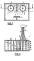
- FIG. 1 shows a processing space 1 in which a substrate 2 is located is a substrate carrier 3, is treated by means of plasma 4, 5.
- the plasma 4, 5 is generated here by means of microwaves from a gas which is supplied by gas feeds 6, 7 arrives in the processing chamber 1. A negative pressure prevails in this processing chamber 1.
- the microwaves, which is the gas entering the processing chamber 1 convert into plasma, are via electrically conductive rods 8, 9, which are outside the Processing chamber 1 are connected to microwave generators in the processing chamber 1 introduced.
- These electrically conductive rods 8, 9 are each one Surround quartz tube 10, 11. Microwaves emerge from the bars 8, 9, which the Pass through quartz tubes 10, 11 and excite plasma 4, 5 outside the quartz tubes.
- a partition is located between the two adjacent quartz tubes 10, 11 12 made of electrically conductive material.
- This partition 12 is perpendicular to the plane, which is stretched between the bars 8, 9. It is on a wall of the housing 1 attached and is about the size of the diameter of one of the quartz tubes 10, 11.
- the partition 12 can also Provide passage openings, d. H. be designed as a perforated plate. In this way is a gas or plasma passage through the partition 12 possible, which the training homogeneous plasma fields easier.
- a gas is introduced into the chamber 1 via the gas feeds 6, 7, where it passes through the microwaves are converted into a plasma.
- the distance a between the outside an electrically conductive rod 8, 9 and the partition 12 is preferably a quarter of the wavelength of the microwave emanating from bars 8, 9.
- the processing chamber 1 is usually a vacuum chamber, in which a process gas or several process gases can be entered. By means of microwaves these process gases ionize and thus form a plasma from which ions form on the Precipitate substrate 2.
- the substrate is advantageously negative Potential.
- tubes 10, 11 are preferably made of quartz, other microwave-permeable ones can also be used Materials are used, for example ceramic or Teflon.
- the processing chamber 1 is shown again in a section A-A.
- the substrate 2 and the substrate carrier 3 as well as the conductive rods 8, 9, which are surrounded by the quartz tubes 10, 11.
- a Microwave generator 13 - for example, a coaxial magnetron - to recognize the communicates with a coaxial waveguide 14, the central part of which is an extension of the rod 9 represents.
- the wave running in the coaxial waveguide 14 becomes with the help of a funnel 15 to the conductive rod 9, which acts as a surface waveguide serves, adapted.
- the fields created on the rod 9 are designated 16 to 20 and symbolize Goubau-Harms surface waves.
- rod-shaped microwave radiator shown in FIGS. 1 and 2 can other emitters can also be provided if they produce a homogeneous one Plasma is possible.
- dielectric tube or jacket radiators can be used also belong to the surface wave antennas. Also dielectric rod or Stick radiators or two-wire waveguides are possible.
- Waveguides are used, e.g. B. a slotted coaxial line, a dielectric Image line or a slotted waveguide.
- the quartz tubes 10, 11 are not themselves waveguides, but can be indirect lead to a waveguide, because the directly on the outside of the quartz tubes 10, 11 Ionization is most pronounced.
- the highly ionized plasma particles in immediate Proximity to the outside of the quartz tubes 10, 11 can hereby be like an electrical one Conductors and thus act like the sheath of a coaxial cable.
- a separate microwave generator 13 is provided for a rod 9. It it is also possible to use only one microwave generator for several rods, as shown for example in DE 196 28 949 A1, or microwave generators to be arranged on both sides of a rod and to this from two sides Food.
- the strength of the microwaves decreases with increasing Distance from the microwave generator 13 more and more. Now becomes a mirror image to the microwave generator 13, a second microwave generator at the other end connected to the rod 9, the drop in intensity of the microwaves can be compensated become.
- a quartz tube 10, 11 when microwaves are fed in from one side can be done in different ways.
- the quartz tube 10, 11 on the end opposite the microwave generator 13 like a test tube
- a reflective metal wall can also be the finishing touch form. With a suitable size of the quartz tubes 10, 11 and the microwave wavelengths a kind of resonator can thereby be formed.
- Fig. 3 shows a processing chamber 1 with the same electrically conductive Bars 8, 9 and equipped with the same quartz tubes 10, 11 as the processing chamber 1 of FIG. 1.
- the quartz tubes 10, 11 are in this embodiment however, embedded in an electrically conductive block 42 in such a way that it Block 42 does not surround only that part of the quartz tubes 10, 11 that is through the Opening angle W is designated.
- This opening angle W is preferably between 10 and 90 degrees. With this variant, too, care should be taken that the distance a between the outer circumference of the respective rod 8, 9 and the subsequent one Block 42 a quarter of the wavelength of the emitted microwave corresponds.
- the middle region 21 of the block 42 takes over in this embodiment the function of the partition 12 in FIGS. 1 and 2.
- the advantage of this embodiment is that even with longer structures, d. H. Structures that extend far into the plane of the drawing are largely one homogeneous distribution of the plasma is achieved along these structures. Moreover the gas entering through the inlets 6, 7 must flow closely around the quartz tubes 10, 11, since only a small cylindrical gap 23, 24 between the quartz tubes and the Block 42 is provided. The choice of the width of the columns 23, 24 determines whether a narrowly delimited, very dense plasma is burning within the columns 23, 24 or whether the formation of the plasma is suppressed. In the latter case, it is limited the plasma to the opening angle W.
- FIG. 4 shows a further variant of the invention, in particular in the high-rate coating of large-area molded parts is used.
- this variant it is possible to use a given plasma source with different shaped parts Size and shape to achieve short-term and homogeneous treatment, for example, to adapt a coating.
- Block 42 is now shown as two symmetrical blocks 25, 26, which by a Suction hole 27 are separated.
- Plasma guide parts 28 to 31 are also flanged to the blocks 25, 26.
- the lateral plasma guide parts 28 and 31 are provided with gas guide channels 32, 33, those with corresponding gas routing channels 34, 35 in blocks 25, 26 in Connect.
- the gas guide channels 36, 37, the Plasma guide parts 29, 30 correspond to the corresponding channels 38, 39 in the blocks 25, 26 are connected.
- a first gas via the gas guide channels 6, 7 and a second gas the gas guide channels 38, 35 fed a third gas.
- At 40 is a dividing line between the blocks 25, 26 and the plasma guide parts Designated 28 to 31.
- the plasma guide parts 28 to 31 are on this Separation line 40 releasably connected to the blocks 25, 26, for example by means of screws, which are not shown in FIG. 4.
- the suction holes 27, 52, 53 and Gas guide channels 32, 33, 34, 35, 36, 37, 38, 39 must be designed so that does not form plasma in them. It is crucial that the diameter of Suction hole and gas channels are sufficiently small at a given pressure.
- the plasma guide parts form here 28 to 31 nozzles 50, 51 with funnel-shaped opening.
- the Distribution and the jet characteristic of the nozzles 50, 51 and thus the inflow speed the starting substances in the processing chamber 1 can be changed.
- a heater not shown here, is accommodated in the blocks 25, 26, it can the plasma guide parts 28 to 31 are also heated, since these have a good thermal Have contact with blocks 34, 35.
- the heating of the blocks 25, 26 can by heating spirals, by radiant heat, by induction heating or by other means Way.
- the heating of the blocks 25, 26 and thus the plasma guide parts is in the introduction of certain starting substances through the gas guide channels 34, 6, 38, 39, 7, 35 required because these substances are at a certain temperature must be heated to show the desired reactions in the plasma room.
- With the suction channels 27, 52, 53 and a pump 60 it is possible to produce reaction products to suck out of the processing chamber 1 to the outside.
- FIG. 5 shows a variant of FIG. 4, in which the molded parts which form the substrate 55, are held by supports 56, 57 which are formed that the gas space between the quartz tubes 10, 11 and the surface of the substrate 55 from the rest of the processing chamber 1, z. B. below the substrate 55 or located on the right and left of the supports 56, 57.
- This Apertures 56 to 59 - which does not appear from FIG. 5 - do not have to be as long as the quartz tubes 10, 11, but shorter, so that they face only parts of the plasma hide the rest of the processing chamber from nozzles 50, 51 is coming.
- the rods 8, 9 shown in the embodiments of FIGS. 1 to 5 can be solid or be hollow. If they are hollow, a cooling liquid can flow through the cavity.
Abstract
Description
Die Erfindung betrifft eine Vorrichtung nach dem Oberbegriff des Patentanspruchs 1.The invention relates to a device according to the preamble of
Plasmen sind ionisierte Gase, deren Atome zumindest teilweise eines oder mehrere Elektronen verloren und sich in positive Ionen verwandelt haben. Solche Plasmen werden beispielsweise für die Beschichtung, Härtung oder sonstige Bearbeitung von Materialien verwendet.Plasmas are ionized gases, the atoms of which are at least partially one or more Lost electrons and turned into positive ions. Such plasmas are used, for example, for the coating, hardening or other processing of Materials used.
In der Regel erfolgt die Erzeugung solcher Plasmen in Unterdruckbehältern mit Hilfe geeigneter Anregungsmittel.As a rule, such plasmas are generated in vacuum containers with the help suitable stimulants.
Als Anregungsmittel kommen hauptsächlich elektromagnetische Wellen in Frage, unter denen wieder die Mikrowellen eine bevorzugte Stellung einnehmen. Unter Mikrowellen versteht man elektromagnetische Wellen, deren Wellenlängen sich vom Millimeter- bis Dezimeterbereich erstrecken.Mainly electromagnetic waves come under consideration as excitation means which the microwaves again occupy a preferred position. Under microwaves one understands electromagnetic waves, the wavelengths of which extend from the millimeter to decimeter range.
Es ist bereits eine Vorrichtung für die Erzeugung eines Plasmas durch Mikrowellen
bekannt, bei welcher die Mikrowellen über einen Hohlleiter und durch eine Glashaube
in einen Plasmaraum gelangen, der sich über einem Substratteller befindet (DE 40 34
450 A1, Fig. 8). Hierbei ist nur eine einzige in das Plasma einstrahlende Mikrowellenvorrichtung
vorgesehen.It is already a device for generating a plasma using microwaves
known in which the microwaves through a waveguide and through a glass hood
get into a plasma space, which is located above a substrate plate (
Eine andere Art der Einkopplung von Mikrowellen in ein Plasma ist in der DE 41 36 297 A1 beschrieben. Hierbei besitzt die Mikrowellen-Einkoppeleinrichtung einen Innenleiter aus Metall, auf den Mikrowellen eingekoppelt werden. Dieser Innenleiter ist von einem Führungshohlleiter aus isolierendem Material umgeben. Als besonders vorteilhaft wird dabei der Einsatz von drei solchen Einkoppel-Vorrichtungen in einer Plasma-Behandlungskammer angesehen. Diese Einkopplungs-Vorrichtungen liegen dabei unmittelbar einander gegenüber. Another way of coupling microwaves into a plasma is in DE 41 36 297 A1. Here, the microwave coupling device has an inner conductor made of metal, on which microwaves are coupled. This inner conductor is surrounded by a guide waveguide made of insulating material. As special The use of three such coupling devices in one is advantageous Plasma treatment chamber viewed. These coupling devices are located directly facing each other.
Bei einer weiteren Vorrichtung zur Erzeugung von Plasma in einem Unterdruckbehälter ist es bekannt, einen stabförmigen Leiter innerhalb eines Rohres aus isolierendem Werkstoff durch diesen Unterdruckbehälter zu führen (DE 195 03 205 C1, DE 196 28 949 A1). Dabei ist der stabförmige Leiter an beiden Enden an Quellen zur Erzeugung der elektromagnetischen Wechselfelder angeschlossen.In another device for generating plasma in a vacuum container it is known to isolate a rod-shaped conductor inside a tube Guide material through this vacuum tank (DE 195 03 205 C1, DE 196 28 949 A1). The rod-shaped conductor is at both ends at sources for generation of the alternating electromagnetic fields connected.
Eine ähnliche Vorrichtung ist auch aus der DE 196 28 954 A1 bekannt, wobei jedoch der Raum zwischen dem stabförmigen Leiter und dem Rohr mit einem festen Dielektrikum ausgefüllt ist.A similar device is also known from DE 196 28 954 A1, however the space between the rod-shaped conductor and the tube with a solid dielectric is filled out.
Nachteilig ist bei diesen bekannten Vorrichtungen, dass dann, wenn mehrere Mikrowellen ausstrahlende Antennen nebeneinander angeordnet sind, ein Großteil der Mikrowellenleistung nicht zum Erzeugen von Plasma dient, sondern zu den Mikrowellensendern zurückläuft. Um Beschädigungen der Mikrowellenerzeuger zu vermeiden, müssen hierbei teure Zirkulatoren eingesetzt werden. Eine Ausbildung von homogenen Plasmafeldern ist unter diesen Umständen nur unzureichend möglich.A disadvantage of these known devices is that when several microwaves radiating antennas are arranged side by side, a large part of the microwave power is not used to generate plasma, but to the microwave transmitters runs back. To avoid damaging the microwave generators, expensive circulators must be used. An education of homogeneous Under these circumstances, plasma fields are only insufficiently possible.
Der Erfindung liegt deshalb die Aufgabe zugrunde, den Anteil der für die Erzeugung eines Plasmas umgesetzten Mikrowellenleistung, die von benachbarten Sendern oder Antennen ausgestrahlt wird, zu erhöhen.The invention is therefore based on the object, the proportion of the generation a microwave power converted by plasma from neighboring transmitters or Antennas being broadcast increase.
Diese Aufgabe wird gemäß den Merkmalen des Patentanspruchs 1 gelöst.This object is achieved in accordance with the features of
Die Erfindung betrifft somit eine Vorrichtung zur Erzeugung eines Plasmas durch Mikrowellenanregung. Hierbei wird zwischen wenigstens zwei Mikrowellenstrahlern, die sich im Plasmaraum befinden, eine Sperre aus elektrisch leitendem Material vorgesehen. Die physikalischen Hintergründe, weshalb die Mikrowellenenergie bei Einfügung der Sperre überwiegend für die Ionisierung von Gasen verbraucht wird, sind im Einzelnen nicht bekannt. Es ist jedoch zu vermuten, dass die Sperre verhindert, dass sich die Mikrowellen der beiden Mikrowellenstrahler gegenseitig beeinflussen und somit ein beachtlicher Teil der elektrischen Leistung der Mikrowellenstrahler nicht in die Erzeugung von Plasma umgesetzt werden kann.The invention thus relates to a device for generating a plasma by microwave excitation. Here, between at least two microwave radiators are located in the plasma room, a lock made of electrically conductive material is provided. The physical background, why the microwave energy when inserted The lock is mainly used for the ionization of gases not known. However, it is suspected that the lock prevents it from happening the microwaves of the two microwave radiators influence one another and thus a considerable part of the electrical power of the microwave radiators is not included in the Generation of plasma can be implemented.
Der mit der Erfindung erzielte Vorteil besteht insbesondere darin, dass durch Interferenzen keine Energie mehr verloren geht, die für die Ionisierung eines Gases zum Plasma benötigt wird. Wird ohne Verwendung einer erfindungsgemäßen Zwischenwand eine elektromagnetische Leistung von beispielsweise 1 600 Watt in das Gas/Plasma eingekoppelt, so gehen mehr als 500 Watt durch Interferenzen oder Reflexionen verloren. Bei Verwendung der Zwischenwand reduziert sich die nicht für die Plasmaerzeugung effektive Leistung auf weniger als 50 Watt. Durch die Entkopplung der Mikrowellenantennen kann somit eine kleinere und damit preiswertere Mikrowellenquelle zum Einsatz kommen. Außerdem entfällt der Einbau eines Zirkulators, der bei Nichtverwendung der erfindungsgemäßen Trennwand erforderlich ist und die rücklaufende Energie von der Mikrowellenquelle fernhalten soll. Zirkulatoren sind passive, nichtreziproke Mehrtore mit mindestens drei Toren, bei denen die in ein Tor eingespeiste Leistung um eine geringe Durchgangsdämpfung geschwächt und nur an einem Tor angeboten wird, während alle anderen Tore weitgehend entkoppelt sind, wobei an ihnen nur die um eine hohe Sperrdämpfung verminderte Leistung angeboten wird.The advantage achieved by the invention is in particular that of interference no more energy is lost that is needed for the ionization of a gas Plasma is needed. Will without using a partition according to the invention an electromagnetic power of, for example, 1,600 watts in that Coupled gas / plasma, so more than 500 watts go through interference or reflections lost. When using the partition, it is not reduced for the Plasma generating effective power to less than 50 watts. By decoupling the microwave antenna can thus be a smaller and therefore cheaper microwave source are used. In addition, the installation of a circulator, the if the partition wall according to the invention is not used, and keep returning energy away from the microwave source. Are circulators passive, non-reciprocal multi-gates with at least three gates, in which the one gate Power fed in weakened by a low through loss and only on one gate is offered, while all other gates are largely decoupled, only the power reduced by a high barrier damping is offered on them becomes.
Ausführungsbeispiele der Erfindung sind in den Zeichnungen dargestellt und werden im Folgenden näher beschrieben. Es zeigen:
- Fig. 1
- einen Querschnitt durch eine Plasmakammer mit Mikrowellenanregung;
- Fig. 2
- einen Längsschnitt A-A durch die in Fig. 1 dargestellte Plasmakammer;
- Fig. 3
- einen Querschnitt durch eine zweite Ausführungsform einer Plasmakammer mit Mikrowellenanregung;
- Fig. 4
- einen Längsschnitt durch eine dritte Ausführungsform einer Plasmakammer mit Mikrowellenanregung;
- Fig. 5
- eine Abwandlung der Ausführungsform gemäß Fig. 4.
- Fig. 1
- a cross section through a plasma chamber with microwave excitation;
- Fig. 2
- a longitudinal section AA through the plasma chamber shown in Fig. 1;
- Fig. 3
- a cross section through a second embodiment of a plasma chamber with microwave excitation;
- Fig. 4
- a longitudinal section through a third embodiment of a plasma chamber with microwave excitation;
- Fig. 5
- a modification of the embodiment according to FIG. 4.
In der Fig. 1 ist ein Bearbeitungsraum 1 dargestellt, in dem ein Substrat 2, das sich auf
einem Substratträger 3 befindet, mittels Plasma 4, 5 behandelt wird. Das Plasma 4, 5
wird hierbei mittels Mikrowellen aus einem Gas erzeugt, das durch Gaszuführungen 6,
7 in die Bearbeitungskammer 1 gelangt. In dieser Bearbeitungskammer 1 herrscht Unterdruck.
Die Mikrowellen, welche das in die Bearbeitungskammer 1 eingetretene Gas
in Plasma umwandeln, werden über elektrische leitende Stäbe 8, 9, die außerhalb der
Bearbeitungskammer 1 mit Mikrowellenerzeugern verbunden sind, in die Bearbeitungskammer
1 eingeführt. Diese elektrisch leitenden Stäbe 8, 9 sind mit jeweils einem
Quarzrohr 10, 11 umgeben. Aus den Stäben 8, 9 treten Mikrowellen aus, welche die
Quarzrohre 10, 11 durchdringen und außerhalb der Quarzrohre das Plasma 4, 5 anregen.1 shows a
Dadurch, dass die elektrisch leitenden Stäbe 8, 9 selbst nicht mit dem Plasma 4, 5 in
Berührung kommen, schlägt sich auch kein Material aus dem Plasma 4, 5 auf ihnen
nieder. Zwischen den Stäben 8, 9 und dem Quarzrohr herrscht Atmosphärendruck,
sodass sich in diesem Raum kein Plasma ausbilden kann. Außerhalb der Quarzrohre
10, 11 herrscht jedoch Unterdruck, sodass das dort befindliche Gas durch die Mikrowellen
angeregt und in Plasma umgeformt werden kann. The fact that the electrically
Zwischen den beiden benachbarten Quarzrohren 10, 11 befindet sich eine Trennwand
12 aus elektrisch leitendem Material. Diese Trennwand 12 steht senkrecht auf der Ebene,
die zwischen den Stäben 8, 9 aufgespannt ist. Sie ist an einer Wand des Gehäuses 1
befestigt und ist etwa so groß wie der Durchmesser eines der Quarzrohre 10, 11. Durch
diese Trennwand 12 wird vermieden, dass sich die von den beiden Stäben 8, 9 ausgehenden
Mikrowellen durch Interferenz auslöschen oder auf sonstige Weise beeinflussen.
Da die Mikrowellen die metallische Trennwand 12 nicht durchdringen können,
sondern von dieser reflektiert werden, kann es nicht zu Überlagerungen der von den
Stäben 8, 9 ausgehenden Wellen kommen. Die Trennwand 12 kann dabei auch mit
Durchtrittsöffnungen versehen, d. h. als Lochblech ausgebildet sein. Auf diese Weise
ist ein Gas- bzw. Plasmadurchtritt durch die Trennwand 12 möglich, was die Ausbildung
homogener Plasmafelder erleichtert.A partition is located between the two
In der Regel - insbesondere wenn großflächige Substrate 2 zu bearbeiten sind - wird
man mehr als zwei Quarzrohre 10, 11 nebeneinander anordnen und zwischen jeweils
zwei benachbarten Rohren eine Trennwand aus elektrisch leitendem Material anordnen.As a rule - especially when large-
Über die Gaszuführungen 6, 7 wird ein Gas in die Kammer 1 eingeleitet, wo es durch
die Mikrowellen in ein Plasma umgewandelt wird. Der Abstand a zwischen der Außenseite
eines elektrisch leitenden Stabs 8, 9 und der Trennwand 12 beträgt vorzugsweise
ein Viertel der Wellenlänge der von den Stäben 8, 9 ausgehenden Mikrowelle.
Durch die Wahl eines λ/4-Abstands ist die Phasendifferenz zwischen der von dem Stab
9 abgestrahlten Mikrowelle und der von der leitfähigen Zwischenwand 12 reflektierten
Mikrowelle genau 360 Grad, weil ein 180-Grad-Phasensprung auftritt, sodass sich beide
Wellen nicht auslöschen, sondern verstärken. Hierdurch kann eine Feldüberhöhung
auftreten, die ein sicheres Zündverhalten begünstigt.A gas is introduced into the
Die Bearbeitungskammer 1 ist in der Regel eine Vakuumkammer, in die ein Prozessgas
oder mehrere Prozessgase eingegeben werden. Mittels der Mikrowellen werden
diese Prozessgase ionisiert und bilden somit ein Plasma, aus dem sich Ionen auf dem
Substrat 2 niederschlagen. Hierbei wird das Substrat in vorteilhafter Weise auf negatives
Potential gelegt.The
Obgleich die Rohre 10, 11 vorzugsweise aus Quarz bestehen, können auch andere mikrowellendurchlässige
Materialien verwendet werden, beispielsweise Keramik oder
Teflon. Although the
In der Fig. 2 ist die Bearbeitungskammer 1 noch einmal in einem Schnitt A-A dargestellt.
Man erkennt hierbei wieder das Substrat 2 und den Substratträger 3 sowie die
leitenden Stäbe 8, 9, die von den Quarzrohren 10, 11 umgeben sind. Außerdem ist ein
Mikrowellengenerator 13 - beispielsweise ein Koaxialmagnetron - zu erkennen, der
mit einem Koaxial-Hohlleiter 14 in Verbindung steht, dessen zentraler Teil eine Verlängerung
des Stabs 9 darstellt. Die im Koaxial-Hohlleiter 14 verlaufende Welle wird
mit Hilfe eines Trichters 15 an den leitenden Stab 9, der als Oberflächen-Wellenleiter
dient, angepasst.2, the
Die auf dem Stab 9 entstehenden Felder sind mit 16 bis 20 bezeichnet und symbolisieren
Goubau-Harms'sche Oberflächenwellen.The fields created on the
Statt des in den Fig. 1 und 2 dargestellten stabförmigen Mikrowellenstrahlers können auch andere Strahler vorgesehen werden, wenn mit ihnen die Erzeugung eines homogenen Plasmas möglich ist.Instead of the rod-shaped microwave radiator shown in FIGS. 1 and 2 can other emitters can also be provided if they produce a homogeneous one Plasma is possible.
Beispielsweise können dielektrische Rohr- oder Mantelstrahler verwendet werden, die ebenfalls zu den Oberflächenwellenantennen zählen. Auch dielektrische Stab- oder Stielstrahler oder Zweidraht-Wellenleiter kommen in Frage.For example, dielectric tube or jacket radiators can be used also belong to the surface wave antennas. Also dielectric rod or Stick radiators or two-wire waveguides are possible.
Desgleichen können auch andere nicht-abstrahlende und nur die Wellen führende Wellenleiter verwendet werden, z. B. eine geschlitzte Koaxialleitung, eine dielektrische Bildleitung oder ein Schlitzhohlleiter.Likewise, other non-emitting and only the waves can lead Waveguides are used, e.g. B. a slotted coaxial line, a dielectric Image line or a slotted waveguide.
Die Quarzrohre 10, 11 stellen selbst keinen Wellenleiter dar, können jedoch mittelbar
zu einer Wellenleitung führen, da direkt auf der Außenseite der Quarzrohre 10, 11 die
Ionisation am stärksten ausgeprägt ist. Die stark ionisierten Plasmateilchen in unmittelbarer
Nähe zur Außenseite der Quarzrohre 10, 11 können hierdurch wie ein elektrischer
Leiter und damit wie der Mantel eines Koaxialkabels wirken.The
In der Fig. 2 ist für einen Stab 9 ein eigener Mikrowellengenerator 13 vorgesehen. Es
ist indessen auch möglich, für mehrere Stäbe nur einen Mikrowellengenerator zu verwenden,
wie dies etwa in der DE 196 28 949 A1 dargestellt ist, oder Mikrowellengeneratoren
auf beiden Seiten eines Stabs anzuordnen und diesen von zwei Seiten aus zu
speisen.2, a
Bei einseitiger Speisung des Stabs 9 fällt die Stärke der Mikrowellen mit zunehmender
Entfernung vom Mikrowellengenerator 13 immer mehr ab. Wird nun spiegelbildlich
zum Mikrowellengenerator 13 ein zweiter Mikrowellengenerator an das andere Ende
des Stabs 9 angeschlossen, so kann der Intensitätsabfall der Mikrowellen kompensiert
werden. When the
Der Abschluss eines Quarzrohrs 10, 11 bei einseitiger Einspeisung von Mikrowellen
kann auf verschiedene Weise erfolgen. Zum einen kann das Quarzrohr 10, 11 an dem
dem Mikrowellengenerator 13 gegenüberliegenden Ende wie ein Reagenzglas abgeschlossen
sein, zum andern kann aber auch eine reflektierende Metallwand den Abschluss
bilden. Bei geeigneter Größe der Quarzrohre 10, 11 und der Mikrowellen-Wellenlängen
kann hierdurch eine Art Resonator gebildet werden.The termination of a
Die Fig. 3 zeigt eine Bearbeitungskammer 1, die mit den gleichen elektrisch leitenden
Stäben 8, 9 und mit den gleichen Quarzrohren 10, 11 bestückt ist wie die Bearbeitungskammer
1 der Fig. 1. Die Quarzrohre 10, 11 sind bei dieser Ausführungsform
jedoch in einen elektrisch leitenden Block 42 eingelassen, und zwar derart, dass dieser
Block 42 nur denjenigen Teil der Quarzrohre 10, 11 nicht umgibt, der durch den
Öffnungswinkel W bezeichnet ist. Dieser Öffnungswinkel W liegt vorzugsweise zwischen
10 und 90 Grad. Auch bei dieser Variante sollte darauf geachtet werden, dass
der Abstand a zwischen dem äußeren Umfang des jeweiligen Stabs 8, 9 und dem anschließenden
Block 42 einem Viertel der Wellenlänge der abgestrahlten Mikrowelle
entspricht. Der mittlere Bereich 21 des Blocks 42 übernimmt bei diesem Ausführungsbeispiel
die Funktion der Trennwand 12 in den Fig. 1 und 2.Fig. 3 shows a
Der Vorteil dieser Ausführungsform besteht darin, dass auch bei längeren Strukturen,
d. h. Strukturen, die sich weit in die Zeichenebene hinein erstrecken, eine weitgehend
homogene Verteilung des Plasmas entlang dieser Strukturen erzielt wird. Außerdem
muss das durch die Einlässe 6, 7 eintretende Gas die Quarzrohre 10, 11 eng umströmen,
da nur ein kleiner zylindrischer Spalt 23, 24 zwischen den Quarzrohren und dem
Block 42 vorgesehen ist. Durch die Wahl der Weite der Spalten 23, 24 wird bestimmt,
ob innerhalb der Spalten 23, 24 ein eng begrenztes, sehr dichtes Plasma brennt oder ob
die Ausbildung des Plasmas unterdrückt wird. Im letztgenannten Fall beschränkt sich
das Plasma auf den Öffnungswinkel W.The advantage of this embodiment is that even with longer structures,
d. H. Structures that extend far into the plane of the drawing are largely one
homogeneous distribution of the plasma is achieved along these structures. Moreover
the gas entering through the
In der Fig. 4 ist eine weitere Variante der Erfindung dargestellt, die insbesondere bei der Hochratenbeschichtung von großflächigen Formteilen zur Anwendung kommt. Mit dieser Variante ist es möglich, eine gegebene Plasmaquelle an Formteile unterschiedlicher Größe und Gestalt zur Erzielung möglichst kurzzeitiger und homogener Behandlung, beispielsweise einer Beschichtung, anzupassen.4 shows a further variant of the invention, in particular in the high-rate coating of large-area molded parts is used. With In this variant it is possible to use a given plasma source with different shaped parts Size and shape to achieve short-term and homogeneous treatment, for example, to adapt a coating.
Im Unterschied zu der in Fig. 3 dargestellten Vorrichtung ist der dort einheitliche
Block 42 nunmehr als zwei symmetrische Blöcke 25, 26 dargestellt, die durch eine
Absaugbohrung 27 getrennt sind. In contrast to the device shown in FIG. 3, the device there is
Außerdem sind an die Blöcke 25, 26 Plasma-Führungsteile 28 bis 31 angeflanscht. In
den seitlichen Plasma-Führungsteilen 28 und 31 sind Gasführungskanäle 32, 33 vorgesehen,
die mit entsprechenden Gasführungskanälen 34, 35 in den Blöcken 25, 26 in
Verbindung stehen. Entsprechendes gilt für die Gasführungskanäle 36, 37, die den
Plasma-Führungsteilen 29, 30 entsprechen, die mit entsprechenden Kanälen 38, 39 in
den Blöcken 25, 26 verbunden sind. Über die Gasführungskanäle 34, 39 wird beispielsweise
ein erstes Gas, über die Gasführungskanäle 6, 7 ein zweites Gas und über
die Gasführungskanäle 38, 35 ein drittes Gas eingespeist.
Mit 40 ist eine Trennungslinie zwischen den Blöcken 25, 26 und den Plasma-Führungsteilen
28 bis 31 bezeichnet. Die Plasma-Führungsteile 28 bis 31 sind an dieser
Trennungslinie 40 mit den Blöcken 25, 26 lösbar verbunden, etwa mittels Schrauben,
die in der Fig. 4 nicht dargestellt sind. Die Absaugbohrungen 27, 52, 53 und die
Gasführungskanäle 32, 33, 34, 35, 36, 37, 38, 39 müssen so ausgebildet sein, dass sich
in ihnen kein Plasma ausbildet. Entscheidend hierfür ist, dass die Durchmesser von
Absaugbohrung und Gaskanälen bei gegebenem Druck hinreichend klein sind.At 40 is a dividing line between the
Durch die Gasführungskanäle 32 bis 39 werden die Ausgangssubstanzen für den Plasmaprozess
in die Bearbeitungskammer 1 geleitet. Hierbei bilden die Plasma-Führungsteile
28 bis 31 Düsen 50, 51 mit trichterförmiger Öffnung.Through the
Durch Austausch der Plasma-Führungsteile 28 bis 31 kann in einfacher Weise die
Verteilung und die Strahlcharakteristik der Düsen 50, 51 und somit die Einströmgeschwindigkeit
der Ausgangssubstanzen in die Bearbeitungskammer 1 verändert werden.By replacing the
Ist in den Blöcken 25, 26 eine hier nicht dargestellte Heizung untergebracht, so können
die Plasma-Führungsteile 28 bis 31 mitgeheizt werden, da diese einen guten thermischen
Kontakt zu den Blöcken 34, 35 haben. Die Aufheizung der Blöcke 25, 26 kann
durch Heizspiralen, durch Heizstrahlung, durch Induktionsheizung oder auf sonstige
Weise erfolgen. Das Aufheizen der Blöcke 25, 26 und damit der Plasma-Führungsteile
ist bei der Einführung bestimmter Ausgangssubstanzen durch die Gasführungskanäle
34, 6, 38, 39, 7, 35 erforderlich, weil diese Substanzen auf eine bestimmte Temperatur
aufgeheizt sein müssen, um die gewünschten Reaktionen im Plasmaraum zu zeigen.
Mit den Absaugkanälen 27, 52, 53 und einer Pumpe 60 ist es möglich, Reaktionsprodukte
aus der Bearbeitungskammer 1 nach außen zu saugen.If a heater, not shown here, is accommodated in the
In der Fig. 5 ist eine Variante der Fig. 4 dargestellt, bei welcher die Formteile, welche
das Substrat 55 bilden, von Trägern 56, 57 gehalten werden, die so ausgebildet sind,
dass sie den Gasraum zwischen den Quarzrohren 10, 11 und der Oberfläche des Substrats
55 vom Rest der Bearbeitungskammer 1, die sich z. B. unterhalb des Substrats
55 bzw. rechts und links von den Trägern 56, 57 befindet, abtrennen. Hierbei weisen
die Träger 56, 57 Blenden 58, 59 auf, welche das Substrat 55 tragen und außerdem
nicht zu beschichtende Bereiche von Formteilen im Plasmaraum abtrennen. Diese
Blenden 56 bis 59 müssen - was aus der Fig. 5 nicht hervorgeht - nicht ebenso lang wie
die Quarzrohre 10, 11 sein, sondern kürzer, sodass sie nur Teile des Plasmas gegenüber
dem Rest der Bearbeitungskammer ausblenden, das von den Düsen 50, 51
kommt.5 shows a variant of FIG. 4, in which the molded parts which
form the
Die bei den Ausführungsformen der Fig. 1 bis 5 gezeigten Stäbe 8, 9 können massiv
oder auch hohl sein. Sind sie hohl, kann durch den Hohlraum eine Kühlflüssigkeit fließen.The
Claims (18)
Applications Claiming Priority (2)
| Application Number | Priority Date | Filing Date | Title |
|---|---|---|---|
| DE1999128876 DE19928876A1 (en) | 1999-06-24 | 1999-06-24 | Device for locally generating a plasma in a treatment chamber by means of microwave excitation |
| DE19928876 | 1999-06-24 |
Publications (2)
| Publication Number | Publication Date |
|---|---|
| EP1063678A2 true EP1063678A2 (en) | 2000-12-27 |
| EP1063678A3 EP1063678A3 (en) | 2004-01-07 |
Family
ID=7912336
Family Applications (1)
| Application Number | Title | Priority Date | Filing Date |
|---|---|---|---|
| EP00112949A Withdrawn EP1063678A3 (en) | 1999-06-24 | 2000-06-20 | Device for microwave powered plasma generation in a cavity |
Country Status (3)
| Country | Link |
|---|---|
| EP (1) | EP1063678A3 (en) |
| JP (1) | JP2001058127A (en) |
| DE (1) | DE19928876A1 (en) |
Cited By (5)
| Publication number | Priority date | Publication date | Assignee | Title |
|---|---|---|---|---|
| WO2008046553A1 (en) * | 2006-10-16 | 2008-04-24 | Iplas Innovative Plasma Systems Gmbh | Device and method for locally producing microwave plasma |
| WO2011064084A1 (en) * | 2009-11-11 | 2011-06-03 | Roth & Rau Muegge Gmbh | Device for generating plasma by means of microwaves |
| DE102010043940A1 (en) * | 2010-11-15 | 2012-05-16 | Forschungsverbund Berlin E.V. | Microwave resonator ICP |
| WO2019233750A1 (en) * | 2018-06-06 | 2019-12-12 | Meyer Burger (Germany) Gmbh | Linear microwave plasma source having separated plasma chambers |
| WO2019233703A1 (en) * | 2018-06-06 | 2019-12-12 | Meyer Burger (Germany) Gmbh | Plasma treatment device having a linear microwave plasma source and having a gas-conducting device |
Citations (4)
| Publication number | Priority date | Publication date | Assignee | Title |
|---|---|---|---|---|
| EP0335675A2 (en) * | 1988-03-29 | 1989-10-04 | Canon Kabushiki Kaisha | Large area microwave plasma apparatus |
| US4908486A (en) * | 1986-06-05 | 1990-03-13 | Nearctic Research Centre | Resonant cavity of a microwave drier |
| US5202095A (en) * | 1988-12-27 | 1993-04-13 | Matsushita Electric Industrial Co., Ltd. | Microwave plasma processor |
| US5478459A (en) * | 1993-10-28 | 1995-12-26 | Leybold Aktiengesellschaft | Plasma sputtering installation with microwave enhancement |
Family Cites Families (5)
| Publication number | Priority date | Publication date | Assignee | Title |
|---|---|---|---|---|
| DE4136297A1 (en) * | 1991-11-04 | 1993-05-06 | Plasma Electronic Gmbh, 7024 Filderstadt, De | Localised plasma prodn. in treatment chamber - using microwave generator connected to coupling device which passes through the wall of the chamber without using a coupling window |
| DE19628949B4 (en) * | 1995-02-02 | 2008-12-04 | Muegge Electronic Gmbh | Device for generating plasma |
| DE19503205C1 (en) * | 1995-02-02 | 1996-07-11 | Muegge Electronic Gmbh | Device for generating a plasma in low pressure container e.g. for hardware items surface treatment by plasma etching and plasma deposition |
| DE19540543A1 (en) * | 1995-10-31 | 1997-05-07 | Leybold Ag | Apparatus for coating a substrate by means of a chemical vapour deposition process |
| DE19608949A1 (en) * | 1996-03-08 | 1997-09-11 | Ralf Dr Spitzl | Device for generating powerful microwave plasmas |
-
1999
- 1999-06-24 DE DE1999128876 patent/DE19928876A1/en not_active Withdrawn
-
2000
- 2000-06-20 EP EP00112949A patent/EP1063678A3/en not_active Withdrawn
- 2000-06-23 JP JP2000189657A patent/JP2001058127A/en not_active Withdrawn
Patent Citations (4)
| Publication number | Priority date | Publication date | Assignee | Title |
|---|---|---|---|---|
| US4908486A (en) * | 1986-06-05 | 1990-03-13 | Nearctic Research Centre | Resonant cavity of a microwave drier |
| EP0335675A2 (en) * | 1988-03-29 | 1989-10-04 | Canon Kabushiki Kaisha | Large area microwave plasma apparatus |
| US5202095A (en) * | 1988-12-27 | 1993-04-13 | Matsushita Electric Industrial Co., Ltd. | Microwave plasma processor |
| US5478459A (en) * | 1993-10-28 | 1995-12-26 | Leybold Aktiengesellschaft | Plasma sputtering installation with microwave enhancement |
Cited By (10)
| Publication number | Priority date | Publication date | Assignee | Title |
|---|---|---|---|---|
| WO2008046553A1 (en) * | 2006-10-16 | 2008-04-24 | Iplas Innovative Plasma Systems Gmbh | Device and method for locally producing microwave plasma |
| WO2011064084A1 (en) * | 2009-11-11 | 2011-06-03 | Roth & Rau Muegge Gmbh | Device for generating plasma by means of microwaves |
| CN103003913A (en) * | 2009-11-11 | 2013-03-27 | 米格有限责任公司 | Device for generating plasma by means of microwaves |
| CN103003913B (en) * | 2009-11-11 | 2016-02-24 | 米格有限责任公司 | For generating the device of plasma by microwave |
| US10290471B2 (en) | 2009-11-11 | 2019-05-14 | Muegge Gmbh | Device for generating plasma by means of microwaves |
| DE102009044496B4 (en) | 2009-11-11 | 2023-11-02 | Muegge Gmbh | Device for generating plasma using microwaves |
| DE102010043940A1 (en) * | 2010-11-15 | 2012-05-16 | Forschungsverbund Berlin E.V. | Microwave resonator ICP |
| DE102010043940B4 (en) * | 2010-11-15 | 2012-08-30 | Forschungsverbund Berlin E.V. | Microwave resonator ICP |
| WO2019233750A1 (en) * | 2018-06-06 | 2019-12-12 | Meyer Burger (Germany) Gmbh | Linear microwave plasma source having separated plasma chambers |
| WO2019233703A1 (en) * | 2018-06-06 | 2019-12-12 | Meyer Burger (Germany) Gmbh | Plasma treatment device having a linear microwave plasma source and having a gas-conducting device |
Also Published As
| Publication number | Publication date |
|---|---|
| DE19928876A1 (en) | 2000-12-28 |
| EP1063678A3 (en) | 2004-01-07 |
| JP2001058127A (en) | 2001-03-06 |
Similar Documents
| Publication | Publication Date | Title |
|---|---|---|
| DE19503205C1 (en) | Device for generating a plasma in low pressure container e.g. for hardware items surface treatment by plasma etching and plasma deposition | |
| EP2839500B1 (en) | Microwave plasma generating device and method for operating the same | |
| EP0593931B1 (en) | Microwave plasmas producing device | |
| DE4136297A1 (en) | Localised plasma prodn. in treatment chamber - using microwave generator connected to coupling device which passes through the wall of the chamber without using a coupling window | |
| EP0486943B1 (en) | Device for the excitation of a uniform microwave field | |
| DE4319717A1 (en) | Device for generating planar low pressure plasma using a coil with its axis parallel to the surface of a coupling window | |
| DE2504860B2 (en) | Microwave heating device | |
| EP0511492A1 (en) | Method and apparatus for treatment or coating of substrates | |
| DE7228091U (en) | ION SOURCE WITH HIGH FREQUENCY CAVITY RESONATOR | |
| DE4028525A1 (en) | MICROWAVE PLASMA SOURCE DEVICE | |
| DE3111305A1 (en) | MICROWAVE DISCHARGE ION SOURCE | |
| WO1998054748A1 (en) | Device for producing plasma | |
| EP1183709B1 (en) | Linearly extended device for large-surface microwave treatment and for large surface plasma production | |
| EP1063678A2 (en) | Device for microwave powered plasma generation in a cavity | |
| WO2019141337A1 (en) | Microwave plasma device | |
| DE4100462C2 (en) | ||
| DD263648B5 (en) | Device for the generation of a microwave plasma with a large expansion and homogeneity | |
| DE69907687T2 (en) | Plasma processing apparatus with electrically conductive wall | |
| DE2441767A1 (en) | PLASMA SOURCE LARGE CROSS SECTION AND ION ACCELERATOR | |
| DE19801366B4 (en) | Device for generating plasma | |
| DE10341239B4 (en) | ECR plasma source with linear plasma outlet | |
| EP2499654A1 (en) | Device for generating plasma by means of microwaves | |
| DE4301188C2 (en) | Device for coating or etching substrates | |
| DE102020113578A1 (en) | Microwave treatment facility | |
| DE4431785A1 (en) | Plasma device |
Legal Events
| Date | Code | Title | Description |
|---|---|---|---|
| PUAI | Public reference made under article 153(3) epc to a published international application that has entered the european phase |
Free format text: ORIGINAL CODE: 0009012 |
|
| AK | Designated contracting states |
Kind code of ref document: A2 Designated state(s): AT BE CH CY DE DK ES FI FR GB GR IE IT LI LU MC NL PT SE |
|
| AX | Request for extension of the european patent |
Free format text: AL;LT;LV;MK;RO;SI |
|
| RAP1 | Party data changed (applicant data changed or rights of an application transferred) |
Owner name: LEYBOLD OPTICS GMBH |
|
| PUAL | Search report despatched |
Free format text: ORIGINAL CODE: 0009013 |
|
| AK | Designated contracting states |
Kind code of ref document: A3 Designated state(s): AT BE CH CY DE DK ES FI FR GB GR IE IT LI LU MC NL PT SE |
|
| AX | Request for extension of the european patent |
Extension state: AL LT LV MK RO SI |
|
| 17P | Request for examination filed |
Effective date: 20040110 |
|
| AKX | Designation fees paid |
Designated state(s): CH DE FR GB IT LI |
|
| STAA | Information on the status of an ep patent application or granted ep patent |
Free format text: STATUS: THE APPLICATION IS DEEMED TO BE WITHDRAWN |
|
| 18D | Application deemed to be withdrawn |
Effective date: 20070101 |